EP0262007A1 - Durchflusskontrolle-Nachlaufeinrichtung für hydraulische Anlage, insbesondere für Kraftfahrzeug-Servolenkung - Google Patents
Durchflusskontrolle-Nachlaufeinrichtung für hydraulische Anlage, insbesondere für Kraftfahrzeug-Servolenkung Download PDFInfo
- Publication number
- EP0262007A1 EP0262007A1 EP19870401886 EP87401886A EP0262007A1 EP 0262007 A1 EP0262007 A1 EP 0262007A1 EP 19870401886 EP19870401886 EP 19870401886 EP 87401886 A EP87401886 A EP 87401886A EP 0262007 A1 EP0262007 A1 EP 0262007A1
- Authority
- EP
- European Patent Office
- Prior art keywords
- chamber
- pilot
- valve
- bore
- passage
- Prior art date
- Legal status (The legal status is an assumption and is not a legal conclusion. Google has not performed a legal analysis and makes no representation as to the accuracy of the status listed.)
- Granted
Links
- 238000009434 installation Methods 0.000 title claims abstract description 8
- 238000002955 isolation Methods 0.000 claims abstract description 5
- 230000002093 peripheral effect Effects 0.000 claims description 7
- 230000000694 effects Effects 0.000 claims description 4
- 230000001105 regulatory effect Effects 0.000 claims description 4
- 230000001276 controlling effect Effects 0.000 claims description 3
- 239000012528 membrane Substances 0.000 description 5
- 239000012530 fluid Substances 0.000 description 3
- 230000008485 antagonism Effects 0.000 description 1
- 230000006399 behavior Effects 0.000 description 1
- 230000002301 combined effect Effects 0.000 description 1
- 239000004020 conductor Substances 0.000 description 1
- 238000012986 modification Methods 0.000 description 1
- 230000004048 modification Effects 0.000 description 1
- 230000002085 persistent effect Effects 0.000 description 1
- 238000004804 winding Methods 0.000 description 1
Images
Classifications
-
- B—PERFORMING OPERATIONS; TRANSPORTING
- B62—LAND VEHICLES FOR TRAVELLING OTHERWISE THAN ON RAILS
- B62D—MOTOR VEHICLES; TRAILERS
- B62D6/00—Arrangements for automatically controlling steering depending on driving conditions sensed and responded to, e.g. control circuits
-
- Y—GENERAL TAGGING OF NEW TECHNOLOGICAL DEVELOPMENTS; GENERAL TAGGING OF CROSS-SECTIONAL TECHNOLOGIES SPANNING OVER SEVERAL SECTIONS OF THE IPC; TECHNICAL SUBJECTS COVERED BY FORMER USPC CROSS-REFERENCE ART COLLECTIONS [XRACs] AND DIGESTS
- Y10—TECHNICAL SUBJECTS COVERED BY FORMER USPC
- Y10T—TECHNICAL SUBJECTS COVERED BY FORMER US CLASSIFICATION
- Y10T137/00—Fluid handling
- Y10T137/2496—Self-proportioning or correlating systems
- Y10T137/2559—Self-controlled branched flow systems
- Y10T137/2574—Bypass or relief controlled by main line fluid condition
- Y10T137/2605—Pressure responsive
- Y10T137/263—Plural sensors for single bypass or relief valve
Definitions
- the present invention relates to controlled flow control devices for hydraulic installation, in particular for vehicle power steering, comprising a pressure source having an outlet connected to an inlet of a hydraulic distributor of the open center type for controlling a hydraulic motor, the distributor having a return output to a tank, and, more particularly, a device of the type comprising, in a body, a slide valve modulator assembly interposed in a bypass circuit between the output of the pressure source and the cover, and hydraulically controlled, by the effect of pressure differential, by an electromagnetically controlled pilot valve creating the pressure differential.
- a flow control device of this type is described in document EP-A-0 072 732 in the name of the applicant.
- the pilot valve is disposed between the pilot chamber of the slide valve modulator and the outlet to the tank, thus modulating a leakage rate as a function of the pilot pressure itself varying as a function of fluctuations at the outlet of the pressure source, in an arrangement which is difficult to adjust and which requires relatively sophisticated pilot valve control electronics.
- the object of the present invention is to propose a device of the type considered in a new arrangement, with more stable and reliable operation and making it possible to simplify the electronic control.
- the pilot valve is disposed between the sheet and an intermediate point of the branch circuit to which the return outlet of the distributor is connected, the intermediate point itself being located directly downstream of the modulator assembly.
- the pressure differential created by the pilot valve and controlling the modulator assembly, depends only on the opening of the pilot valve because the latter is traversed by the entire flow supplying the hydraulic installation, i.e. a substantially constant flow.
- Another object of the present invention is to propose a device of the type defined above memorizing a determined operating condition in the event of failure of the control valve control electronics, and thus providing increased safety.
- the modulator assembly comprises a pilot slide actuatable by the pressure differential on either side of the pilot valve and lockable in any position by an isolation valve coupled to the pilot valve in case of failure of the electromagnetic control device of the latter.
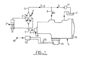
- a hydraulic power steering system of a vehicle comprising a distributor of the open center type 1, for example of the rotary valve type, controlled by an actuator 2, typically connected to the vehicle steering wheel (not shown), for selectively supplying the opposing chambers of a hydraulic motor 3 with a modulated fluid pressure coming from a source of fluid under pressure 4 connected to a high pressure inlet 5 of the distributor 1.
- a controlled bypass flow control device is interposed between a low pressure tank or tank 7, from which typically draws the pressure source 4, and, on the one hand , a bypass line 8 connected at an intermediate point between the pressure source 4 and the high pressure inlet 5 of the distributor 1, and, on the other hand, the return outlet 9 towards the tank 7 of the distributor 1.
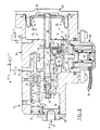
- the device 6 comprises a body 10 in which are formed a first bore 11 and a second bore 12 advantageously parallel.
- the second bore 12 is a blind bore closed by a plug 13 and in which is slidably mounted a flow regulator drawer 14 of the closed center type, while the first bore 11 opens on one side into an outlet chamber 15 and, on the other side, in an intermediate chamber 16 formed in the body.
- the drawer 14 delimits in the second bore 12 an inlet chamber 17 into which an inlet passage 18 opens, intended to be connected to the bypass pipe 8, and a passage 19 communicating with the first bore 11.
- the drawer 14 delimits in the second bore 12 another chamber 20 closed by the plug 13 and communicating with the intermediate chamber 16 by a regulating orifice 21 capable of being selectively partially obscured (thereby constituting a variable restriction) by the adjacent end of the drawer 14 which is biased in the direction towards the inlet chamber 17 by a spring 22 bearing on the plug 13.
- the drawer 14 has a peripheral annular groove 23 communicating with another passage 24 establishing communication between the first bore 11 and the second bore 12, and with the other chamber 20 by a radial passage 25 and an axial internal passage 26.
- a pilot or needle slide 27 one end of which protrudes into the outlet chamber 15, is secured to a piston means, typically of the elastic membrane type 28 clamped by its periphery between the body 10 and a cover 29 attached to the body, the membrane 28 thus separating the outlet chamber 15 from a pilot chamber 30 delimited externally by the cover 29.
- the membrane 28 and, consequently, the drawer 27, is biased in the direction towards the cover 29 by a spring 31 disposed in the outlet chamber 15 into which an outlet passage 32 opens intended to be connected to the cover 7.
- the drawer 27 comprises, between the passages 19 and 24, an annular peripheral groove profiled in cone shape 33 permanently communicating with the passage 19 and selectively communicating, depending on the position of the drawer 27, with the passage 24 opening into the annular groove 23 of the drawer 14 forming with the passage 24 a re variable necking.
- the end of the slide 27 connected to the membrane 28 is formed internally with a blind axial bore 34 communicating permanently with the pilot chamber 30 and, by a radial passage 35, with a peripheral annular groove 36 at the level of which opens a passage 37 establishing communication between the first bore 11 and an internal chamber formed in a valve body 38 defining a valve passage 39 selectively closable by a valve element 40 biased by a spring 41 in the direction tending to close the passage 39 and integral with 'a rod 42 extending through the passage 39 and bearing, under the effect of the spring 41, against a pilot valve element 43, typically in the form of an annular plate, defining an annular fluid passage with variable section 44 with an annular shoulder 45 between a cylindrical chamber 46, in which partially extends the valve body 38, and a cavity 47 in which is mounted in a sealed manner a solenoid valve actuator 48 comprising a plunger 49 with which cooperates in support, via a central axis, the pilot valve element 43 under the effect of a spring 50 disposed in the cylindrical chamber 46.
- the cylindrical chamber 46 communicates permanently with the intermediate chamber 16 through a passage 51 formed in the body 10, advantageously parallel to the first bore 11, and the cavity 47 communicates permanently with the outlet chamber 15 through a passage 52 formed in the body 10.
- the intermediate chamber 16 is delimited on the outside by a obturator connection 90 for connection to the return output 9 of the distributor 1.
- the slide 27 comprises, between the grooves 33 and 36, an intermediate peripheral annular groove 53 into which opens a passage 54 formed between the first bore 11 and the cylindrical chamber 46 in order to prevent the high pressure in the groove 33 cannot pass through the groove 36 and, from there, towards the pilot chamber 30.
- the slide 27 advantageously comprises an end 62 opposite the membrane 28, projecting into the intermediate chamber 16 and comprising a axial bore 55, closed externally by a plug 56 and communicating with the groove 33, and with a series of radial restrictions 57, axially spaced from one another, opening into the bore 55 so as to selectively establish a leakage flow rate between the groove 33 and chamber 16 when the pressure differential between the pilot chamber 30 and the outlet chamber 15 exceeds a determined value.
- the winding of the solenoid valve 48 is connected by conductors 58 to an electronic control unit 59 developing control signals for the solenoid valve 48 as a function of significant parameters of the operation of the vehicle, in particular its speed, provided by at least one sensor 60.
- the solenoid valve 48 will be of the high air gap type (for example of the order of 3 mm), before which the variations in passage 44 are negligible (with a valve lift of the order of 0.1 mm for a valve 43 having a 20mm diameter, thus constituting a practically constant air gap system.
- a bypass flow q (for example up to 3 liters per minute for a nominal pump flow rate Q of 5 liters per minute) can be subtracted from the flow Q sent by the source 4 to the inlet 5 of the distributor 1, via the bypass circuit 8 passing through the inlet chamber 17, the groove 33, the passage 24, the chamber 20 and the passage of regulation 21 to recombine, in the intermediate chamber 16, with the output flow Q - q coming from the distributor 1, all of the flow Q from the pressure source 4 thus arriving, via the passage 51, at the cylindrical chamber 46.
- a pressure P prevails in the intermediate chamber 16, in the cylindrical chamber 46 as well as, when the passage 39 is open, in the pilot chamber 30 while, depending on the annular passage 44, it prevails in the cavity 47, as well as in the outlet chamber 15, a reduced pressure P ⁇ , the difference P - P ⁇ depending only on the opening of the valve element 43 and therefore on the control intensity of the solenoid valve 48 , the flow rate Q passing through the annular passage 44 being substantially constant.
- This pressure differential P - P ⁇ determines, in antagonism of the force of the spring 31, the position of the slide 27 and therefore the magnitude of the derivative flow q whose small fluctuations are regulated by the slide 14.
- valve element 43 moves, under the combined effect of the pressure differential P - P ⁇ and the spring 50, in the direction tending to open the annular passage 44, which thus causes closing passage 39 through the valve 40 thereby isolating the pilot chamber 30 from the cylindrical chamber 46, so that the device remains in the position it previously occupied at the time of electrical failure without therefore suddenly changing, due to this failure, the behavior of the hydraulic installation.
- the device in the event of a persistent failure of the electrical control of the solenoid valve 48, the device tends to occupy a configuration which does not provide any flow diversion, thereby guaranteeing operation at full power available for the hydraulic installation, which particularly suitable for vehicle parking operations, providing a minimum pressure drop in the return circuit from the distributor 1 to the cover 7.
Landscapes
- Engineering & Computer Science (AREA)
- Chemical & Material Sciences (AREA)
- Combustion & Propulsion (AREA)
- Transportation (AREA)
- Mechanical Engineering (AREA)
- Fluid-Driven Valves (AREA)
- Flow Control (AREA)
- Vending Machines For Individual Products (AREA)
- Auxiliary Drives, Propulsion Controls, And Safety Devices (AREA)
Applications Claiming Priority (2)
| Application Number | Priority Date | Filing Date | Title |
|---|---|---|---|
| FR8613077 | 1986-09-18 | ||
| FR8613077A FR2604268B1 (fr) | 1986-09-18 | 1986-09-18 | Dispositif asservi de controle de debit pour installation hydraulique notamment pour servo-direction de vehicule |
Publications (2)
| Publication Number | Publication Date |
|---|---|
| EP0262007A1 true EP0262007A1 (de) | 1988-03-30 |
| EP0262007B1 EP0262007B1 (de) | 1989-06-14 |
Family
ID=9339074
Family Applications (1)
| Application Number | Title | Priority Date | Filing Date |
|---|---|---|---|
| EP19870401886 Expired EP0262007B1 (de) | 1986-09-18 | 1987-08-14 | Durchflusskontrolle-Nachlaufeinrichtung für hydraulische Anlage, insbesondere für Kraftfahrzeug-Servolenkung |
Country Status (6)
| Country | Link |
|---|---|
| US (1) | US4825751A (de) |
| EP (1) | EP0262007B1 (de) |
| JP (1) | JPS6389907A (de) |
| DE (1) | DE3760238D1 (de) |
| ES (1) | ES2008872B3 (de) |
| FR (1) | FR2604268B1 (de) |
Cited By (1)
| Publication number | Priority date | Publication date | Assignee | Title |
|---|---|---|---|---|
| EP0454336A2 (de) * | 1990-04-27 | 1991-10-30 | Ford Motor Company Limited | Solenoidservoventil mit variabler Öffnung für Servolenksystem mit variabler Unterstützung |
Families Citing this family (3)
| Publication number | Priority date | Publication date | Assignee | Title |
|---|---|---|---|---|
| DE19717796C2 (de) * | 1997-04-26 | 1999-03-04 | Zahnradfabrik Friedrichshafen | Hilftskraftlenkung mit hydraulischer Hilfskraftunterstützung |
| EP1234748B1 (de) * | 2001-02-23 | 2003-11-12 | Visteon Global Technologies, Inc. | Dämpfungsventil für hydraulisch unterstütztes Lenkungssystem |
| CN100337870C (zh) * | 2005-07-29 | 2007-09-19 | 浙江大学 | 汽车双联式液压动力转向泵 |
Citations (4)
| Publication number | Priority date | Publication date | Assignee | Title |
|---|---|---|---|---|
| EP0071909A2 (de) * | 1981-08-05 | 1983-02-16 | Nissan Motor Co., Ltd. | Servolenkungseinrichtung für Fahrzeuge |
| EP0072732A1 (de) * | 1981-08-11 | 1983-02-23 | BENDIX France | Durchflussregler für eine Servolenkungseinrichtung |
| EP0089512A2 (de) * | 1982-03-18 | 1983-09-28 | Nissan Motor Co., Ltd. | Fahrzeugservolenkung mit Lenkkraftkontrollsystem |
| US4485883A (en) * | 1982-09-30 | 1984-12-04 | Ford Motor Company | Power steering system with vehicle speed-sensitive flow |
Family Cites Families (7)
| Publication number | Priority date | Publication date | Assignee | Title |
|---|---|---|---|---|
| US3596677A (en) * | 1969-01-13 | 1971-08-03 | Rex Chainbelt Inc | Remotely operable pressure compensated flow control valve |
| US3980779A (en) * | 1972-02-01 | 1976-09-14 | Bayer Aktiengesellschaft | 3-Amino-1,2,4-benzotriazine-1,4-di-N-oxide compositions and method of using same |
| JPS4971633A (de) * | 1972-11-15 | 1974-07-11 | ||
| US4211254A (en) * | 1978-10-30 | 1980-07-08 | Modular Controls Corporation | Normally closed pressure compensated flow control valve |
| US4462566A (en) * | 1982-02-08 | 1984-07-31 | French Bruce C | Pressure compensated flow control system |
| DE3232536C2 (de) * | 1982-09-01 | 1986-10-23 | Herion-Werke Kg, 7012 Fellbach | Ventilanordnung zur Steuerung und Überwachung des Arbeitsdruckes eines Verbrauchers |
| JPS61155060A (ja) * | 1984-12-27 | 1986-07-14 | Jidosha Kiki Co Ltd | 動力舵取装置の油圧反力装置 |
-
1986
- 1986-09-18 FR FR8613077A patent/FR2604268B1/fr not_active Expired - Fee Related
-
1987
- 1987-08-14 ES ES87401886T patent/ES2008872B3/es not_active Expired
- 1987-08-14 DE DE8787401886T patent/DE3760238D1/de not_active Expired
- 1987-08-14 EP EP19870401886 patent/EP0262007B1/de not_active Expired
- 1987-09-04 US US07/094,356 patent/US4825751A/en not_active Expired - Fee Related
- 1987-09-18 JP JP62232690A patent/JPS6389907A/ja active Pending
Patent Citations (4)
| Publication number | Priority date | Publication date | Assignee | Title |
|---|---|---|---|---|
| EP0071909A2 (de) * | 1981-08-05 | 1983-02-16 | Nissan Motor Co., Ltd. | Servolenkungseinrichtung für Fahrzeuge |
| EP0072732A1 (de) * | 1981-08-11 | 1983-02-23 | BENDIX France | Durchflussregler für eine Servolenkungseinrichtung |
| EP0089512A2 (de) * | 1982-03-18 | 1983-09-28 | Nissan Motor Co., Ltd. | Fahrzeugservolenkung mit Lenkkraftkontrollsystem |
| US4485883A (en) * | 1982-09-30 | 1984-12-04 | Ford Motor Company | Power steering system with vehicle speed-sensitive flow |
Cited By (2)
| Publication number | Priority date | Publication date | Assignee | Title |
|---|---|---|---|---|
| EP0454336A2 (de) * | 1990-04-27 | 1991-10-30 | Ford Motor Company Limited | Solenoidservoventil mit variabler Öffnung für Servolenksystem mit variabler Unterstützung |
| EP0454336A3 (en) * | 1990-04-27 | 1992-03-04 | Ford Motor Company Limited | Variable-orifice, servo-solenoid valve for a variable-assist power steering system |
Also Published As
| Publication number | Publication date |
|---|---|
| FR2604268B1 (fr) | 1995-05-24 |
| DE3760238D1 (en) | 1989-07-20 |
| US4825751A (en) | 1989-05-02 |
| EP0262007B1 (de) | 1989-06-14 |
| FR2604268A1 (fr) | 1988-03-25 |
| JPS6389907A (ja) | 1988-04-20 |
| ES2008872B3 (es) | 1989-08-16 |
Similar Documents
| Publication | Publication Date | Title |
|---|---|---|
| EP0524032B1 (de) | Druckregeleinrichtung für hydraulischen Schaltkreis | |
| EP0194927B1 (de) | Drucksteuer-Servoeinrichtung für hydraulische Anlage, insbesondere für Kraftfahrzeugservolenkung | |
| WO1993009485A1 (fr) | Dispositif de regulation de pression pour circuit hydraulique | |
| FR2578920A1 (fr) | Dispositif asservi de controle de debit pour installation hydraulique, notamment pour direction assistee de vehicule | |
| EP0262007B1 (de) | Durchflusskontrolle-Nachlaufeinrichtung für hydraulische Anlage, insbesondere für Kraftfahrzeug-Servolenkung | |
| EP0187051B1 (de) | Zweibereich-Druckreglervorrichtung | |
| FR2633072A1 (fr) | Circuit de commande, de regulation et de controle d'un debit de fluide | |
| EP0072732B1 (de) | Durchflussregler für eine Servolenkungseinrichtung | |
| FR2813926A1 (fr) | Dispositif hydraulique a soupapes | |
| EP0401061B1 (de) | Modulator und Servolenkungskreis mit einem solchen Modulator | |
| EP0166630B1 (de) | Bedienungsvorrichtung für Bremsdruckregler | |
| EP0194928B1 (de) | Drucksteuer-Servoeinrichtung für hydraulische Anlage, insbesondere für Kraftfahrzeugservolenkung | |
| EP0202154B1 (de) | Durchlaufkontroll-Servovorrichtung für hydraulische Einrichtung, insbesondere für Kraftfahrzeug-Servolenkung | |
| EP0278814A1 (de) | Kraftstoffregler für Turbomaschinen | |
| EP0784553B1 (de) | Elektroventil für hydraulische druckregelung und anwendung in bremsanlagen | |
| FR2620660A1 (fr) | Regulateur de niveau pour vehicule automobile | |
| EP0467724B1 (de) | Verteiler für Druckflüssigkeit | |
| FR2735884A1 (fr) | Electrovalve de regulation de pression pour circuit hydraulique | |
| FR2767299A1 (fr) | Procede et mecanisme de commande du flux volumique d'un systeme hydraulique de direction assistee de vehicules automobiles | |
| EP0290700B1 (de) | Druckflüssigkeitsmodulationseinheit, insbesondere für Fahrzeugservolenkung | |
| EP0396433B1 (de) | Fluidsteuervorrichtung und ein diese umfassender Servolenkungskreis | |
| EP0467723B1 (de) | Flüssigkeitsverteiler mit zweifacher Fluid-Steuerung | |
| FR2573169A1 (fr) | Appareil de positionnement a distance d'une valve | |
| FR2661458A1 (fr) | Circuit de commande d'un verin hydraulique a double effet et distributeur a tiroir pour un tel circuit. | |
| FR2513326A1 (fr) | Dispositif de commande hydraulique comprenant un distributeur |
Legal Events
| Date | Code | Title | Description |
|---|---|---|---|
| PUAI | Public reference made under article 153(3) epc to a published international application that has entered the european phase |
Free format text: ORIGINAL CODE: 0009012 |
|
| 17P | Request for examination filed |
Effective date: 19870902 |
|
| AK | Designated contracting states |
Kind code of ref document: A1 Designated state(s): DE ES GB IT |
|
| 17Q | First examination report despatched |
Effective date: 19881121 |
|
| GRAA | (expected) grant |
Free format text: ORIGINAL CODE: 0009210 |
|
| AK | Designated contracting states |
Kind code of ref document: B1 Designated state(s): DE ES GB IT |
|
| GBT | Gb: translation of ep patent filed (gb section 77(6)(a)/1977) | ||
| REF | Corresponds to: |
Ref document number: 3760238 Country of ref document: DE Date of ref document: 19890720 |
|
| ITF | It: translation for a ep patent filed | ||
| PLBE | No opposition filed within time limit |
Free format text: ORIGINAL CODE: 0009261 |
|
| STAA | Information on the status of an ep patent application or granted ep patent |
Free format text: STATUS: NO OPPOSITION FILED WITHIN TIME LIMIT |
|
| 26N | No opposition filed | ||
| ITTA | It: last paid annual fee | ||
| PGFP | Annual fee paid to national office [announced via postgrant information from national office to epo] |
Ref country code: GB Payment date: 19960710 Year of fee payment: 10 |
|
| PGFP | Annual fee paid to national office [announced via postgrant information from national office to epo] |
Ref country code: ES Payment date: 19960814 Year of fee payment: 10 |
|
| PGFP | Annual fee paid to national office [announced via postgrant information from national office to epo] |
Ref country code: DE Payment date: 19960828 Year of fee payment: 10 |
|
| PG25 | Lapsed in a contracting state [announced via postgrant information from national office to epo] |
Ref country code: GB Free format text: LAPSE BECAUSE OF NON-PAYMENT OF DUE FEES Effective date: 19970814 |
|
| PG25 | Lapsed in a contracting state [announced via postgrant information from national office to epo] |
Ref country code: ES Free format text: LAPSE BECAUSE OF NON-PAYMENT OF DUE FEES Effective date: 19970815 |
|
| GBPC | Gb: european patent ceased through non-payment of renewal fee |
Effective date: 19970814 |
|
| PG25 | Lapsed in a contracting state [announced via postgrant information from national office to epo] |
Ref country code: DE Free format text: LAPSE BECAUSE OF NON-PAYMENT OF DUE FEES Effective date: 19980501 |
|
| REG | Reference to a national code |
Ref country code: ES Ref legal event code: FD2A Effective date: 19980910 |
|
| PG25 | Lapsed in a contracting state [announced via postgrant information from national office to epo] |
Ref country code: IT Free format text: LAPSE BECAUSE OF NON-PAYMENT OF DUE FEES Effective date: 20050814 |