EP0261998B1 - Hydraulischer Anschlagpuffer für Kraftfahrzeugaufhängung - Google Patents
Hydraulischer Anschlagpuffer für Kraftfahrzeugaufhängung Download PDFInfo
- Publication number
- EP0261998B1 EP0261998B1 EP19870401419 EP87401419A EP0261998B1 EP 0261998 B1 EP0261998 B1 EP 0261998B1 EP 19870401419 EP19870401419 EP 19870401419 EP 87401419 A EP87401419 A EP 87401419A EP 0261998 B1 EP0261998 B1 EP 0261998B1
- Authority
- EP
- European Patent Office
- Prior art keywords
- travel
- stop
- motor vehicle
- vehicle suspension
- suspension
- Prior art date
- Legal status (The legal status is an assumption and is not a legal conclusion. Google has not performed a legal analysis and makes no representation as to the accuracy of the status listed.)
- Expired - Lifetime
Links
- 239000000725 suspension Substances 0.000 title claims description 18
- 230000006835 compression Effects 0.000 claims description 5
- 238000007906 compression Methods 0.000 claims description 5
- 239000007788 liquid Substances 0.000 claims description 5
- 229920001971 elastomer Polymers 0.000 claims description 2
- 239000000806 elastomer Substances 0.000 claims 1
- 239000000463 material Substances 0.000 claims 1
- LYCAIKOWRPUZTN-UHFFFAOYSA-N Ethylene glycol Chemical compound OCCO LYCAIKOWRPUZTN-UHFFFAOYSA-N 0.000 description 3
- 238000010586 diagram Methods 0.000 description 1
- 239000013536 elastomeric material Substances 0.000 description 1
- 239000002184 metal Substances 0.000 description 1
- 238000000034 method Methods 0.000 description 1
- XLYOFNOQVPJJNP-UHFFFAOYSA-N water Substances O XLYOFNOQVPJJNP-UHFFFAOYSA-N 0.000 description 1
Images

Classifications
-
- B—PERFORMING OPERATIONS; TRANSPORTING
- B60—VEHICLES IN GENERAL
- B60G—VEHICLE SUSPENSION ARRANGEMENTS
- B60G7/00—Pivoted suspension arms; Accessories thereof
- B60G7/04—Buffer means for limiting movement of arms
-
- F—MECHANICAL ENGINEERING; LIGHTING; HEATING; WEAPONS; BLASTING
- F16—ENGINEERING ELEMENTS AND UNITS; GENERAL MEASURES FOR PRODUCING AND MAINTAINING EFFECTIVE FUNCTIONING OF MACHINES OR INSTALLATIONS; THERMAL INSULATION IN GENERAL
- F16F—SPRINGS; SHOCK-ABSORBERS; MEANS FOR DAMPING VIBRATION
- F16F13/00—Units comprising springs of the non-fluid type as well as vibration-dampers, shock-absorbers, or fluid springs
- F16F13/04—Units comprising springs of the non-fluid type as well as vibration-dampers, shock-absorbers, or fluid springs comprising both a plastics spring and a damper, e.g. a friction damper
- F16F13/06—Units comprising springs of the non-fluid type as well as vibration-dampers, shock-absorbers, or fluid springs comprising both a plastics spring and a damper, e.g. a friction damper the damper being a fluid damper, e.g. the plastics spring not forming a part of the wall of the fluid chamber of the damper
- F16F13/08—Units comprising springs of the non-fluid type as well as vibration-dampers, shock-absorbers, or fluid springs comprising both a plastics spring and a damper, e.g. a friction damper the damper being a fluid damper, e.g. the plastics spring not forming a part of the wall of the fluid chamber of the damper the plastics spring forming at least a part of the wall of the fluid chamber of the damper
Definitions
- the present invention relates to a suspension of a motor vehicle comprising, for each wheel, elastic means interposed between a first element connected to the structure of the vehicle and a second element connected to the wheel spindle, and attack and detent stops for limit the movement of the second element relative to the first.
- a suspension of this kind is described in particular in French patent FR-A-2,442,731.
- the suspension according to the invention is characterized in that this attack stop consists of a hollow body of elastomeric material, which is full of liquid, is closed in leaktight manner by a rigid frame and comprises an inner pin or protuberance coming to meet the armature after a certain crushing of the stop, so that the attack stop is likely to work first in extension, then in compression.
- the inner pin can be connected by ribs to the inner face of the hollow body. When the stop is crushed, these ribs work in extension and prevent the pawn from flaming.
- a wheel 1 which is rotatably mounted on a rocket 2. This is connected by a connecting rod 3 to the structure 4 of the vehicle and is integral with a suspension cylinder 5.
- this cylinder can slide the cylindrical part 6 of a piston which further comprises a tube 7 integral with the part 6.
- This tube can slide in a bearing 8 provided at the upper part of the cylinder 5 and is mounted in the structure 4.
- Cetube is connected by a conduit 9 and a damper 10 to a hydropneumatic element 11 which, in a manner known per se, contains a pressurized gas and a liquid, this element thus being in communication with the cylinder 5 by the conduit 9 and the tube 7.
- the tube 7 and the duct 9 are mounted on the structure in a manner compatible with the travel of the wheel 1.
- a leading stop 12 suitable for being encountered by the connecting rod 3 when the axle travel reaches a value specified below, is fixed to the structure 4 by means of a console 13.
- a relaxation stop 14 is mounted on the tube 7 between the piston 6 and the bearing 8.
- the attack stop 12 comprises a hollow rubber body 15, one end of which is closed while its other end is adhered to a metal washer 16. On this washer is crimped a frame 17 which seals the body 15 and is provided in its center with a fixing screw 18.
- the body 15 contains a liquid, formed for example of 20% water and 80% ethylene glycol and has , at its end opposite to the frame 17, an internal axial protuberance 19 which is connected by ribs 20 to the internal face of the wall of the body 15 and here has a frustoconical axial section.
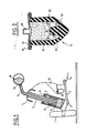
- Figure 3 shows the force exerted on the wheel 1 as a function of the axle travel. If the attack stroke is considered, the force is exerted only by the compression of the element 11 from the origin to the point A corresponding to one third of the maximum possible travel; curve 21 represents the stiffness of the suspension alone.
- the body of the stop 12 works in extension, the liquid which it contains pressing on its walls; it is the same for its ribs 20.
- the elasticity of the stopper is added to that of the element 11 and the stiffness of the assembly is represented by the curve 22. This process, during which the stopper is relatively flexible , continues until the protuberance 19 meets the head of the screw 18. This occurs at point B and the protuberance is shaped so that this encounter takes place in the second third of the travel.
- the protuberance 19 works on compression and the stiffness of the suspension assembly plus stop increases notably, as shown by curve 23; the protuberance 19 is shaped and dimensioned so that this curve 23 is tangentially connected to the curve 22. At point C the protuberance 19 is completely compressed and then limits the travel of the axle. This corresponds to an effort equal to twice the nominal load of the vehicle.
- the relaxation stop 14 is also placed so as to intervene only for a clearance corresponding to one third of the total stroke.
- the maximum travel is obtained for a load equal to the normal load.
Landscapes
- Engineering & Computer Science (AREA)
- Mechanical Engineering (AREA)
- General Engineering & Computer Science (AREA)
- Vehicle Body Suspensions (AREA)
- Springs (AREA)
Claims (3)
Applications Claiming Priority (2)
| Application Number | Priority Date | Filing Date | Title |
|---|---|---|---|
| FR8609937A FR2600949B1 (fr) | 1986-07-02 | 1986-07-02 | Suspension de vehicule automobile a butee d'attaque hydraulique |
| FR8609937 | 1986-07-02 |
Publications (2)
| Publication Number | Publication Date |
|---|---|
| EP0261998A1 EP0261998A1 (de) | 1988-03-30 |
| EP0261998B1 true EP0261998B1 (de) | 1991-01-16 |
Family
ID=9337206
Family Applications (1)
| Application Number | Title | Priority Date | Filing Date |
|---|---|---|---|
| EP19870401419 Expired - Lifetime EP0261998B1 (de) | 1986-07-02 | 1987-06-23 | Hydraulischer Anschlagpuffer für Kraftfahrzeugaufhängung |
Country Status (3)
| Country | Link |
|---|---|
| EP (1) | EP0261998B1 (de) |
| DE (1) | DE3767423D1 (de) |
| FR (1) | FR2600949B1 (de) |
Families Citing this family (2)
| Publication number | Priority date | Publication date | Assignee | Title |
|---|---|---|---|---|
| JPH0367734U (de) * | 1989-10-24 | 1991-07-02 | ||
| FR3052107A1 (fr) * | 2016-06-01 | 2017-12-08 | Peugeot Citroen Automobiles Sa | Systeme de suspension hydraulique d’une roue d'un vehicule |
Family Cites Families (4)
| Publication number | Priority date | Publication date | Assignee | Title |
|---|---|---|---|---|
| FR1497839A (fr) * | 1965-11-17 | 1967-10-13 | Lord Corp | Dispositif de montage amortisseur |
| FR2442731A1 (fr) * | 1978-11-15 | 1980-06-27 | Citroen Sa | Suspension hydropneumatique a deux butees souples de debattement |
| DE3230485A1 (de) * | 1982-08-17 | 1984-02-23 | Fa. Carl Freudenberg, 6940 Weinheim | Fluessigkeitsgedaempftes gummilager |
| FR2557515B1 (fr) * | 1983-12-28 | 1986-05-16 | Citroen Sa | Suspension a garde au sol variable et butees suiveuses |
-
1986
- 1986-07-02 FR FR8609937A patent/FR2600949B1/fr not_active Expired - Fee Related
-
1987
- 1987-06-23 DE DE8787401419T patent/DE3767423D1/de not_active Expired - Fee Related
- 1987-06-23 EP EP19870401419 patent/EP0261998B1/de not_active Expired - Lifetime
Also Published As
| Publication number | Publication date |
|---|---|
| FR2600949B1 (fr) | 1990-07-27 |
| DE3767423D1 (de) | 1991-02-21 |
| FR2600949A1 (fr) | 1988-01-08 |
| EP0261998A1 (de) | 1988-03-30 |
Similar Documents
| Publication | Publication Date | Title |
|---|---|---|
| EP2199164B1 (de) | Dichtung für einen Hauptbremszylinder für ein Kraftfahrzeug | |
| FR2487467A1 (fr) | Dispositif d'accouplement attenuant les vibrations | |
| FR2627565A1 (fr) | Support en caoutchouc a effet d'amortissement hydraulique | |
| EP0469947B1 (de) | Haltebuchse für Kugelgelenk | |
| EP1400405A1 (de) | Scheinwerfer mit Energieabsorptionsmitteln | |
| WO2000045081A1 (fr) | Dispositif de raccordement rapide d'un tube a un element rigide | |
| EP0261998B1 (de) | Hydraulischer Anschlagpuffer für Kraftfahrzeugaufhängung | |
| EP2439111A1 (de) | Hauptzylinder mit Schutzansatzstück | |
| EP1073571B1 (de) | Unterdruckbremskraftverstärker mit kraftgeregelter automatischer unterstützung | |
| EP1603778A1 (de) | Stossdämpferanschlag für ein kraftfahrzeug | |
| WO1997049589A1 (fr) | Maitre-cylindre a deflecteur de choc rapporte | |
| FR2777613A1 (fr) | Manchon elastique a deux armatures; bielette de reprise de couple equipee d'un tel manchon | |
| FR2796609A1 (fr) | Bloc avant perfectionne pour vehicule automobile | |
| FR2742382A1 (fr) | Dispositif de suspension pour vehicules | |
| FR2715702A1 (fr) | Articulation élastique, notamment pour triangle de suspension de véhicule automobile. | |
| FR2559105A1 (fr) | Dispositif d'actionnement d'embrayage | |
| FR2736008A1 (fr) | Module de suspension d'un groupe moto-propulseur sur la structure d'un vehicule automobile | |
| FR2695974A1 (fr) | Dispositif de fixation de l'extrémité d'un amortisseur sur la caisse d'un véhicule automobile, et procédé de montage dudit amortisseur sur la caisse au moyen de ce dispositif. | |
| EP0342078A1 (de) | Verfahren zur Erneuerung von Bremsflüssigkeit | |
| EP0261011B1 (de) | Lastabhängiges Bremsventil | |
| FR2615469A1 (fr) | Train de roues directrices d'un vehicule automobile avec jambes telescopiques a ressort incline | |
| EP0771965B1 (de) | Verbesserte Abdichtungsvorrichtung für ein Rohr oder einen Schwingungsdämpfer, insbesondere einen unter Druck stehenden Einrohr-Schwingungsdämpfer | |
| FR2961322A1 (fr) | Systeme de simulation de freinage, comprenant une pedale de frein | |
| EP0480782B1 (de) | Tandemunterdruckbremskraftverstärker | |
| CN2586008Y (zh) | 摩托车制动器 |
Legal Events
| Date | Code | Title | Description |
|---|---|---|---|
| PUAI | Public reference made under article 153(3) epc to a published international application that has entered the european phase |
Free format text: ORIGINAL CODE: 0009012 |
|
| 17P | Request for examination filed |
Effective date: 19871222 |
|
| AK | Designated contracting states |
Kind code of ref document: A1 Designated state(s): DE GB IT |
|
| 17Q | First examination report despatched |
Effective date: 19891108 |
|
| GRAA | (expected) grant |
Free format text: ORIGINAL CODE: 0009210 |
|
| AK | Designated contracting states |
Kind code of ref document: B1 Designated state(s): DE GB IT |
|
| ITF | It: translation for a ep patent filed | ||
| REF | Corresponds to: |
Ref document number: 3767423 Country of ref document: DE Date of ref document: 19910221 |
|
| GBT | Gb: translation of ep patent filed (gb section 77(6)(a)/1977) | ||
| PLBE | No opposition filed within time limit |
Free format text: ORIGINAL CODE: 0009261 |
|
| STAA | Information on the status of an ep patent application or granted ep patent |
Free format text: STATUS: NO OPPOSITION FILED WITHIN TIME LIMIT |
|
| 26N | No opposition filed | ||
| PGFP | Annual fee paid to national office [announced via postgrant information from national office to epo] |
Ref country code: GB Payment date: 19930615 Year of fee payment: 7 |
|
| PGFP | Annual fee paid to national office [announced via postgrant information from national office to epo] |
Ref country code: DE Payment date: 19930621 Year of fee payment: 7 |
|
| PG25 | Lapsed in a contracting state [announced via postgrant information from national office to epo] |
Ref country code: GB Effective date: 19940623 |
|
| GBPC | Gb: european patent ceased through non-payment of renewal fee |
Effective date: 19940623 |
|
| PG25 | Lapsed in a contracting state [announced via postgrant information from national office to epo] |
Ref country code: DE Effective date: 19950301 |
|
| PG25 | Lapsed in a contracting state [announced via postgrant information from national office to epo] |
Ref country code: IT Free format text: LAPSE BECAUSE OF NON-PAYMENT OF DUE FEES;WARNING: LAPSES OF ITALIAN PATENTS WITH EFFECTIVE DATE BEFORE 2007 MAY HAVE OCCURRED AT ANY TIME BEFORE 2007. THE CORRECT EFFECTIVE DATE MAY BE DIFFERENT FROM THE ONE RECORDED. Effective date: 20050623 |