EP0261960A2 - Apparatus and method for determining fouling tendency of liquid hydrocarbons - Google Patents
Apparatus and method for determining fouling tendency of liquid hydrocarbons Download PDFInfo
- Publication number
- EP0261960A2 EP0261960A2 EP87308438A EP87308438A EP0261960A2 EP 0261960 A2 EP0261960 A2 EP 0261960A2 EP 87308438 A EP87308438 A EP 87308438A EP 87308438 A EP87308438 A EP 87308438A EP 0261960 A2 EP0261960 A2 EP 0261960A2
- Authority
- EP
- European Patent Office
- Prior art keywords
- film
- asphaltenes
- sample
- light
- reflected
- Prior art date
- Legal status (The legal status is an assumption and is not a legal conclusion. Google has not performed a legal analysis and makes no representation as to the accuracy of the status listed.)
- Withdrawn
Links
Images


Classifications
-
- G—PHYSICS
- G01—MEASURING; TESTING
- G01N—INVESTIGATING OR ANALYSING MATERIALS BY DETERMINING THEIR CHEMICAL OR PHYSICAL PROPERTIES
- G01N30/00—Investigating or analysing materials by separation into components using adsorption, absorption or similar phenomena or using ion-exchange, e.g. chromatography or field flow fractionation
- G01N30/90—Plate chromatography, e.g. thin layer or paper chromatography
- G01N30/95—Detectors specially adapted therefor; Signal analysis
-
- G—PHYSICS
- G01—MEASURING; TESTING
- G01N—INVESTIGATING OR ANALYSING MATERIALS BY DETERMINING THEIR CHEMICAL OR PHYSICAL PROPERTIES
- G01N33/00—Investigating or analysing materials by specific methods not covered by groups G01N1/00 - G01N31/00
- G01N33/26—Oils; viscous liquids; paints; inks
- G01N33/28—Oils, i.e. hydrocarbon liquids
- G01N33/2805—Oils, i.e. hydrocarbon liquids investigating the resistance to heat or oxidation
Definitions
- the present invention relates to an apparatus and method for determining the tendency of liquid hydrocarbon streams to foul equipment and more particularly to an apparatus and method for determining oil-asphaltenes incompatibility and related fouling tendency.
- Petroleum streams depending on their asphaltene and oil characteristics, have different precipitating and fouling characteristics with regard to heated oil refinery surfaces.
- the problem of predicting the offending substances in a particular steam such as crude oil which foul heat exchanger equipment in oil refineries and petrochemical plants has been virtually unresolved.
- Equipment fouling by heated hydrocarbon steams which result in inorganic and carbonaceous deposits on heat exchanger surfaces leads to a blockage of flow and a decrease in heat transfer. Both conditions severely reduce heat efficiency in the processing of the crude oil.
- a reliable technique for identifying the problem crudes would enable the operator to apply remedial measures such as removing the offending substances or by adding antifouling inhibitors.
- test unit which is designed to allow measurement of the fluid temperature at the exit of the heat-exchanger while the metal temperature of the heated tube is controlled.
- This configuration provides for close simulation of refinery and petrochemical plant heat-exchanger operations and provides for measurement of the significant effect of fouling which is indicated by the reduction of heat transfer.
- the test unit provides for a thermal fouling evaluation of the crude oil in an accelerated test which is designed to reproduce the fouling problem experienced in a refinery over several months. Acceleration is provided by carrying out test operating temperatures higher than those in a particular refinery unit, so that the prospective level of fouling can be produced in a reasonable period of time (usually 3-4 hours).
- Heat transfer data is obtained by holding the heater tube at a constant temperature while measuring the change in the liquid outlet temperature. As fouling progresses, i.e., carbonaceous deposits build up on the heater tube surface, a decrease in the fluid outlet temperature results.
- the change in liquid outlet temperature with time provides the basic heat data required for comparative evaluation of untreated material and additive-treated material.
- the rate of change in outlet liquid temperature versus time shows relative fouling tendencies.
- the film is preferably selected from TLC plates or polymeric membranes.
- the present invention in one aspect also relates to an apparatus which employs a chromatographic separation on films (e.g. polymeric membrane or TLC plate) and optics for measuring the tendency of liquid hydrocarbons to foul.
- the apparatus comprises, in a preferred embodiment:
- the optical information is converted into a logic level pulse representative of the light reflected.
- These signals during each scan provide a profile of the liquid hydrocarbon sample. By integrating the area of the profile corresponding to the asphaltene separated portion (matrix profile being 0), the characteristic reading of the samples tendency to foul is obtained. This Value can be compared to a standard value of known hydrocarbons.
- the incompatibility of asphaltenes in the liquid hydrocarbon is a measure of the tendency of the liquid to foul.
- the incompatibility may be detected by the use of the film such as TLC plate or polymeric membranes. Depositing a drop of the hydrocarbon stream on the film produces rings of light (non-fouling) components and dark (fouling) components precipitated on the membrane film, usually in the form of a dark ring.
- ring formations may be enhanced by the use of diluents, paraffinic solvents, or asphaltene antisolvents such as n-heptane, iso-octane, and decane or solvents containing polar atoms such as alcohols, ketones, amines, ether, etc.
- the intensity and area of the asphaltene ring when optically compared to the light region provides a reliable indication of the fouling tendency of the liquid hydrocarbon.
- the optical data may be converted to digital output - the value of which classifies a hydrocarbon liquid according to its tendency to foul.
- the method comprises the following steps:
- the difference or ratio of light reflection between the asphaltene ring and the remainder of the sample in or on the plate or membrane provides the indication of fouling tendency of the hydrocarbon stream from which the sample was taken.
- one aspect of the present invention is a method for reducing the fouling tendency of petroleum streams flowing through a vessel.
- the apparatus of the present invention comprises a porous film (e.g. TLC plate or polymeric membrane) 11 capable of chromatographic separation of incompatible asphaltenes for receiving a drop of hydrocarbon liquid, a scanner 12 including light source head and means 13 for moving the scanner 12, means for measuring reflective light, a data acquisition unit 14 and means 15 for converting the data to useful information.
- the apparatus may include means for displaying the results.
- the scanner 12, film 11, and means for moving the light scanner are shown as a single unit 16.
- the unit 16 comprises briefly a support platform 17, a main housing 18 mounted on one end thereof and an end frame member 19 mounted on the other end thereof. Disposed above the platform 17 and extending in parallel relationship with one another are polished rods 21 which interconnect the main housing 18 and frame member 19.
- a bar 22 is slideably mounted on the polished rods 21 and provides means for supporting the scanner 12.
- a vertical rod 23 extends through a central hole of the bar 22 and is secured thereto by set screws (not shown).
- the scanner 12 is mounted to the lower end of the rod 23.
- the rod 23 may be provided with telescopically threaded members with micrometer means (not shown) for adjusting the vertical elevation of the scanner 12 in relation to the film 11
- the scanner 12 comprises a light source and a sensor for measuring the reflected light and converting that into a digital signal which is transmitted to the data acquisition unit 14 by lines 26.
- the means for moving the scanner 12 assembly hori zontally to scan the sample on the polymeric membrane 11 is provided by conventional motor and gear assembly.
- a threaded shaft 27 is mounted by suitable bearings in main housing 18 and has its outer end secured to the bar 22 as at 28.
- rotation of the screw 27 through a conventional threaded drive within housing 18 moves the scanner assembly along the polish rods 21.
- the screw motor and gear reducers should be designed to provide a relatively slow rectilinear motion. About 2 inches per minute is satisfactory for most applications.
- the electronics and circuitry for the instrument including units 14 and 15 may be housed in box 29 underlying support 17.
- the apparatus may include a digital output 31 for indicating the level of the tendency of the sample to foul according to a calibrated scale.
- the scanner 12 may be in the form of an industrial digital bar code such as those commercially available from Hewlett Packard with circuitry for converting the reflected optical information to a logic level pulse representative of the reflected light.
- the scanner 12 may include a separate light source and a high resolution optical reflective sensor, such as Hewlett Packard HEDS-1000.
- the device includes a light emitter and sensor for sensing the visible light from 600-700 nm.
- the pulse signal from the scanner 12 is transmitted to a data acquisition unit such as Hewlett Packard 3421A which converts the pulses into meaningful information that can be represented digitally or graphically by the use of a conventional computer and plotter.
- a data acquisition unit such as Hewlett Packard 3421A which converts the pulses into meaningful information that can be represented digitally or graphically by the use of a conventional computer and plotter.
- the preferred film is a TLC plate or polymeric membrane.
- the TLC plate 11 is preferably a high performance silica gel supported on a glass plate.
- TLC plates which have worked well in the present invention are conventional silica gel plates. These plates have silica gel thickness of about 0.2 mm thickness of silica gel.
- the size of the plate may vary, but a size of about 10 x 10 cm or 5 x 5 cm provides space for many tests. It is believed that asphaltene adsorption plays a major role in the separation of the asphaltene and non-asphaltene, and accordingly finely divided particulate materials which adsorb asphaltenes are preferred TLC plate material.
- the polymeric membrane is preferably a polymeric porous membrane or film made from polymers containing polar atoms such as fluorine, chlorine, oxygen and nitrogen.
- a preferred membrane is made from polyvinylidine difluoride (PVDF).
- PVDF polyvinylidine difluoride
- This membrane (Metricel GAN6) is commercially available from: Gelman Science, Inc. Ann Arbor, Michigan, 48106.
- Other polymeric membranes such as polysulphone Metricel GA6 or GA8 or Tuffryn 1 + T - 100 can also be used.
- Other membrane materials may include cellulose acetate and cellulose nitrate.
- the size of the membrane may vary, but a size from 10 x 10 cm to 5 x 5 cm, with thickness of 0.2 mm will be satisfactory for most applications.
- the membrane is maintained on a glass or impervious plastic support plate.
- the hydrocarbon sample may be used in diluted form (with an asphaltene antisolvent) or undiluted form (neat), on a dry film, or on a film wet with the asphaltene antisolvent.
- a drop of the liquid hydrocarbon is deposited on a flat surface of a film.
- a conventional disposable transfer pipet (Pasteur type 5 3/4") provides means for depositing drops of substantially the same volume on the plate. After a predetermined period of time in which the sample spreads onto or into the film media (usually from 5 minutes to 2 hours), the scanner 12 is passed over the plate scanning the full scope of its radial migration on the film.
- a sample drop 40 as it appears on the film 11 is illustrated in amplified form in Figures 4 and 4A.
- the drop, after spreading comprises an invaded region indicated at 41 and a dark ring region indicated by ring 42.
- a light region 43 outside perimeter 41 sometimes develops. It is believed that this region consists of very light hydrocarbons which separate from the intermediates.
- the interior 46a of the dark asphaltene ring 42 may be dark (as illustrated) indicating asphaltenes or may be lighter.
- the light regions 41 and in some samples region 46a are referred to herein as the matrix regions and contain the compatible (nonfouling) components.
- the light scanner 12 determines the magnitude of the reflected light in both the matrix regions and the asphaltenes region.
- the reflected light increases downward and decreases upward as viewed in Figure 5, 5A, 6, and 6A.
- absorbed light increases upwardly on the plots of Figures 5, 5A, 6, and 6A. Comparing the plot of Figure 5 with the sample of Figure 4, it can be seen that as the scanner 12 moves from right to left, it first encounters a high light reflected area as at 43a which indicates the light hydrocarbon fractions in region 43 of the sample. When the scanner 12 encounters the periphery of region 41 of the sample, the reflected light decreases rapidly to 44 and levels off providing a reading for matrix region 41.
- the tendency to foul will be low. This may be viewed as the volume above the base lines since light reflected is based on the area of the ring and the amplitude of light reflected.
- the data acquisition unit is programmed to integrate the area above base line 44 and 46 and convert that measurement to a digital reading calibrated according to known fouling tendency.
- the above scale was developed by calibrating the apparatus with TFT readings based on hundreds of samples.
- the present invention thus determines the tendency of hydrocarbon liquids to foul equipment and the results correlate well with the tedious TFT method as reflected by the above groupings. Note that the apparatus reading does not correspond to the T of the TFT. However, the groupings (high, medium, low) correlated very well.
- asphaltene incompatibility of the total petroleum stream is indicative of the susceptibility of asphaltenes to separate from the oil, adhere to the heated metal surface, transfer into coke-like material and result in fouling of the metal surface.
- the greater the incompatibility of the asphaltenes in the oil the higher the fouling tendency of the hydrocarbon stream.
- Gel permeation chromatographic (GPC) characterization of two crude oil asphaltenes molecules indicates the presence of molecular weight as high as 5000.
- Paraffinic or polar solvents or their blends can be used to dilute the samples and these are effective over a broad range of oil/solvent ratios.
- Asphaltene is substantially insolvent in these materials. These asphaltene antisolvents must be a low molecular weight, low viscosity and have low boiling characteristics to allow rapid migration on the chromatographic film.
- paraffinic antisolvents are preferably up to C18 straight or branched alkanes.
- suitable antisolvents include pentane, isopentane, hexane, 2-methyl hexane, n-heptane, octane, nonane, decane, iso-octane and the like.
- the polar antisolvents cover a broader spectrum of materials.
- the present polar solvents are organic compounds which are liquids under the conditions of use.
- the term "polar" refers to atoms such as oxygen, sulfur, oxygen, halogens and nitrogen.
- a partial listing of suitable polar antisolvents includes alcohols such as, isobutanol, 2-pentanol, isoamyl alcohol; ketones such as acetone; methyl ethyl ketone; ethers such as diethyl ether, methyl propyl ether; esters such as methyl formate, butyl formate, methyl acetate, methyl propionate; glycol ethers, such as ethylene glycol monomethyl ether, ethylene glycol diethyl ether; heteroatom compounds such as furan, tetrahydrofuran, furfural, methyl pyridine, and the like.
- n-heptane or n-decane were used satisfactorily.
- On-site testing in cold weather may require pentane or isoctane, whereas a refinery site in hot weather such as in Texas or Louisiana where the film 11 plate will have high temperature, may require a high boiling antisolvent such as nonane or decane.
- Asphaltene demulsifiers and other chemicals which will react chemically or physically with asphaltenes to (a) decrease asphaltene solubility or dispersion in oil and/or (b) increase separation of the asphaltenes, and/or (c) increase asphaltenes adhesion or adsorption to the TLC material (e.g., silica gel or polymer membrane).
- TLC material e.g., silica gel or polymer membrane
- Such chemicals include acids, bases, and organic-metallic compounds.
- the present invention of fouling characterization is simple and easy to use in the laboratory and in the field for monitoring crude oil fouling characteristics routinely by nontechnical personnel.
- the method may be used in three ways: (a) use of antisolvent in the oil sample, (b) use of antisolvent on the film, and (c) use of neat sample.
- the use of antisolvent is preferred however since it appears to be the most versatile in the variety of crudes capable of testing.
- the antisolvent can be added to and blended with the crude oil.
- the blend one drop then is deposited on the TLC film.
- the spreading of the sample to form a circular invaded zone will develop in a very short time.
- the sample is then scanned and the reflected light measured as described previously.
- Figures 5 and 6 are representative of the instrument output plot for TLC plate and Figures 5A and 6A for polymeric membrane.
- the ratio of antisolvent to oil will obviously vary from crude to crude, not only for the enhancement of the insolubility of the asphaltenes but also to reduce the viscosity of the crude to an extent to make it operable with the polymeric membrane.
- Light and medium crudes require only a few minutes for development of the chromatographic pattern, whereas heavy crudes, such as the California crudes, may require a few hours.
- the antisolvent is preferably added to the oil in a ratio ranging from 0.2:1 to 1:0.2, more preferably 0.5:1 to 1:0.5 (antisolvent:oil ratio).
- the use of the correct oil/antisolvent ratio is important for the successful separation of asphaltene and oil on the TLC film.
- the antisolvent will insolubilize the asphaltene, especially the low molecular weight part of the asphaltenes and produce a very clear and well defined asphaltene ring on the TLC film, which can then be easily related to fouling characteristics with greater assurance by the unit operator using the test.
- the preferred antisolvents include C5 - C10 hydrocarbons straight and branched alkanes at a ratio wherein the hydrocarbon liquid comprises the major volume proportion.
- the preferred system comprises from 10 to 30 volume percent of pentane, isopentane, hexane, 2 methyl hexane, n-heptane, octane, nonane, decane, isoctane, or mixtures of these and 70 to 90 volume percent of the liquid hydrocarbon.
- the present method can also be used by simply adding one or a few drops of the antisolvent onto the dry film (just to wet the thin film) and then applying a drop of the oil onto the wet film and allowing the chromatogram to develop followed by scanning as described above.
- This method is par ticularly suitable for on-site tests in the refinery. It is also possible to use a combination of the two embodiments of the present invention, which may be useful with very heavy crudes.
- a drop of a high fouling crude oil (as determined by TFT) with antisolvent (1 part volume decane plus 4 parts crude) was placed on the TLC plate (dry) and permitted to migrate for 60 minutes at room temperature.
- the TLC plate sample then was scanned with instrument (1) above and the graph shown in Figure 5 was produced. Note that the plot of Figure 5 corresponds to the sample of Figure 4 previously described.
- the fouling index as read by the Apparatus was 90, indicating a high fouling crude.
- a drop of a high fouling crude oil (as determined by TFT) with antisolvent (1 part volume decane plus 4 parts crude) was placed on the dry polymeric membrane and permitted to migrate for 60 minutes at room temperature.
- the chromatogram on the polymeric membrane then was scanned with instrument (1) above and the graph shown in Figure 5A was produced. Note that the plot of Figure 5A corresponds to the sample of Figure 4A previously described.
- the fouling index as read by the Apparatus was 98, indicating a high fouling crude.
Abstract
Description
- The present invention relates to an apparatus and method for determining the tendency of liquid hydrocarbon streams to foul equipment and more particularly to an apparatus and method for determining oil-asphaltenes incompatibility and related fouling tendency.
- Petroleum streams, depending on their asphaltene and oil characteristics, have different precipitating and fouling characteristics with regard to heated oil refinery surfaces. The problem of predicting the offending substances in a particular steam such as crude oil which foul heat exchanger equipment in oil refineries and petrochemical plants has been virtually unresolved. Equipment fouling by heated hydrocarbon steams which result in inorganic and carbonaceous deposits on heat exchanger surfaces leads to a blockage of flow and a decrease in heat transfer. Both conditions severely reduce heat efficiency in the processing of the crude oil. A reliable technique for identifying the problem crudes would enable the operator to apply remedial measures such as removing the offending substances or by adding antifouling inhibitors.
- There are a number of methods and devices available for determining the rates of fouling of petroleum streams. Conceptually, they are all similar in that they attempt to measure the change in heat transfer from a heated surface to a test fluid. These methods are either not reliable or are time consuming.
- One approach is to use a test unit which is designed to allow measurement of the fluid temperature at the exit of the heat-exchanger while the metal temperature of the heated tube is controlled. This configuration provides for close simulation of refinery and petrochemical plant heat-exchanger operations and provides for measurement of the significant effect of fouling which is indicated by the reduction of heat transfer. The test unit provides for a thermal fouling evaluation of the crude oil in an accelerated test which is designed to reproduce the fouling problem experienced in a refinery over several months. Acceleration is provided by carrying out test operating temperatures higher than those in a particular refinery unit, so that the prospective level of fouling can be produced in a reasonable period of time (usually 3-4 hours). Heat transfer data is obtained by holding the heater tube at a constant temperature while measuring the change in the liquid outlet temperature. As fouling progresses, i.e., carbonaceous deposits build up on the heater tube surface, a decrease in the fluid outlet temperature results. The change in liquid outlet temperature with time provides the basic heat data required for comparative evaluation of untreated material and additive-treated material. The rate of change in outlet liquid temperature versus time shows relative fouling tendencies.
- Current test equipment is only capable of measuring the overall tendency of heated petroleum stream to foul refinery equipment and cannot predict which are the offending substances or fractions.
- An article entitled "Thin-Layer Chromatographic Method for Determination of Asphaltene Content of Crude Oils and Bitumens", authored by Poirer and George, published in 1983 Energy Sources, Volume 7, No. 1, discloses a method which involves determination of asphaltenes content by conventional thin-layer chromatographic (TLC) procedures, extraction of the asphaltenes by toluene, and colorimetric determination of the asphaltenes. This process involves the use of TLC tank with developer solvent. Although described as a fast method, the article states that about 8 hours are required to analyze 15 samples. Moreover, this method measures asphaltene content and not asphaltene/oil incompatibility which is the cause of fouling.
- Hence, it is an advantage of the present invention that an improved method and apparatus which will rapidly indicate the fouling tendency of asphaltene containing petroleum streams is provided. It is a particular advantage the present invention can be employed in the refinery in a very short period of time by unit operators without extensive chemical training. These and other advantages and features will be apparent from the following test.
- The method according to one embodiment of the present invention comprises:
- (a) depositing a liquid hydrocarbon sample onto a film capable of chromatographic separation in a horizontal position;
- (b) permitting the sample to spread radially thereon whereby the incompatible asphaltenes form a ring on the surface of the film and the compatible components invade the matrix of the film;
- (c) scanning the spread circular chromatogram with an energy source (preferably light);
- (d) measuring a property (preferably reflected light) which distinguishes the incompatible asphaltenes ring from the matrix;
- (e) comparing the property of the matrix with that of the incompatible asphaltene ring, the value of which provides an indication of the tendency of the liquid hydrocarbon to foul equipment.
- The film is preferably selected from TLC plates or polymeric membranes.
- The present invention in one aspect also relates to an apparatus which employs a chromatographic separation on films (e.g. polymeric membrane or TLC plate) and optics for measuring the tendency of liquid hydrocarbons to foul. The apparatus comprises, in a preferred embodiment:
- (a) a film (preferably a TLC plate or polymeric membrane) capable of chromatographic separation for receiving a sample of the liquid hydrocarbon on an exposed surface thereof,
- (b) a light scanner for scanning across the chromatogram on the film.
- (c) a light sensor for measuring the light reflected by the sample on the film, and
- (d) means for comparing the light reflected by asphaltenes deposited on the film with the matrix zone within the sample receiving portion. Matrix refers to the invaded zone without the separated asphaltenes. The matrix may be inside and/or outside the asphaltene ring, depending on the crude oil.
- In a preferred embodiment the optical information is converted into a logic level pulse representative of the light reflected. These signals during each scan provide a profile of the liquid hydrocarbon sample. By integrating the area of the profile corresponding to the asphaltene separated portion (matrix profile being 0), the characteristic reading of the samples tendency to foul is obtained. This Value can be compared to a standard value of known hydrocarbons.
- It has been discovered that the incompatibility of asphaltenes in the liquid hydrocarbon is a measure of the tendency of the liquid to foul. The incompatibility may be detected by the use of the film such as TLC plate or polymeric membranes. Depositing a drop of the hydrocarbon stream on the film produces rings of light (non-fouling) components and dark (fouling) components precipitated on the membrane film, usually in the form of a dark ring. These ring formations may be enhanced by the use of diluents, paraffinic solvents, or asphaltene antisolvents such as n-heptane, iso-octane, and decane or solvents containing polar atoms such as alcohols, ketones, amines, ether, etc.
- The intensity and area of the asphaltene ring when optically compared to the light region provides a reliable indication of the fouling tendency of the liquid hydrocarbon. The optical data may be converted to digital output - the value of which classifies a hydrocarbon liquid according to its tendency to foul.
- In a preferred embodiment, the method comprises the following steps:
- (a) depositing a sample amount (usually one drop) of liquid petroleum from the hydrocarbon stream being monitored onto a flat horizontal surface of a TLC plate or polymeric membrane which has the property of chromatographic separation of the incompatible asphaltene by adsorption;
- (b) providing sufficient time for radial outward migration of the sample on or in the plate or membrane (from around 5 minutes to around 2.0 hours) to permit an asphaltene ring to form;
- (c) scanning the migrated sample with a light source; and
- (d) measuring the reflected light throughout the scanned portion.
- The difference or ratio of light reflection between the asphaltene ring and the remainder of the sample in or on the plate or membrane provides the indication of fouling tendency of the hydrocarbon stream from which the sample was taken.
- Once the petroleum stream has been identified as fouling according to the present invention, it can be treated to reduce fouling by incorporating a small quantity of an antifouling agent, such as the well known dispersants used in the refining industry. Thus one aspect of the present invention is a method for reducing the fouling tendency of petroleum streams flowing through a vessel.
-
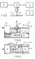
- Figure 1 is a flow diagram schematically illustrating the operation of the apparatus constructed according to the present invention.
- Figure 2 is a side elevational view of the apparatus constructed according to the present invention.
- Figure 3 is a top plan view of the apparatus shown in Figure 2.
- Figures 4 and 4A are enlarged top plan views of asphal tene containing hydrocarbon samples after migration on the TLC plate (Fig. 4) or the membrane (Fig. 4A).
- Figures 5, 5A, 6, and 6A are graphs of high fouling crudes (Fig. 5 and 5A) and low fouling crudes (Fig. 6 and 6A), as measured by the apparatus of the present invention.
- Referring to Figures 1, 2, and 3, the apparatus of the present invention comprises a porous film (e.g. TLC plate or polymeric membrane) 11 capable of chromatographic separation of incompatible asphaltenes for receiving a drop of hydrocarbon liquid, a
scanner 12 including light source head and means 13 for moving thescanner 12, means for measuring reflective light, adata acquisition unit 14 and means 15 for converting the data to useful information. Optionally, the apparatus may include means for displaying the results. - As shown in Figures 2 and 3, the
scanner 12, film 11, and means for moving the light scanner are shown as asingle unit 16. Theunit 16 comprises briefly asupport platform 17, amain housing 18 mounted on one end thereof and anend frame member 19 mounted on the other end thereof. Disposed above theplatform 17 and extending in parallel relationship with one another arepolished rods 21 which interconnect themain housing 18 andframe member 19. Abar 22 is slideably mounted on thepolished rods 21 and provides means for supporting thescanner 12. Avertical rod 23 extends through a central hole of thebar 22 and is secured thereto by set screws (not shown). Thescanner 12 is mounted to the lower end of therod 23. Therod 23 may be provided with telescopically threaded members with micrometer means (not shown) for adjusting the vertical elevation of thescanner 12 in relation to the film 11 - In a preferred embodiment, the
scanner 12 comprises a light source and a sensor for measuring the reflected light and converting that into a digital signal which is transmitted to thedata acquisition unit 14 bylines 26. - The means for moving the
scanner 12 assembly hori zontally to scan the sample on the polymeric membrane 11 is provided by conventional motor and gear assembly. A threadedshaft 27 is mounted by suitable bearings inmain housing 18 and has its outer end secured to thebar 22 as at 28. Thus rotation of thescrew 27 through a conventional threaded drive withinhousing 18 moves the scanner assembly along thepolish rods 21. The screw motor and gear reducers should be designed to provide a relatively slow rectilinear motion. About 2 inches per minute is satisfactory for most applications. - The electronics and circuitry for the
instrument including units box 29underlying support 17. Optionally, the apparatus may include adigital output 31 for indicating the level of the tendency of the sample to foul according to a calibrated scale. - The
scanner 12 may be in the form of an industrial digital bar code such as those commercially available from Hewlett Packard with circuitry for converting the reflected optical information to a logic level pulse representative of the reflected light. Alternatively, thescanner 12 may include a separate light source and a high resolution optical reflective sensor, such as Hewlett Packard HEDS-1000. The device includes a light emitter and sensor for sensing the visible light from 600-700 nm. - The pulse signal from the
scanner 12 is transmitted to a data acquisition unit such as Hewlett Packard 3421A which converts the pulses into meaningful information that can be represented digitally or graphically by the use of a conventional computer and plotter. - As indicated above the preferred film is a TLC plate or polymeric membrane. The TLC plate 11 is preferably a high performance silica gel supported on a glass plate. TLC plates which have worked well in the present invention are conventional silica gel plates. These plates have silica gel thickness of about 0.2 mm thickness of silica gel. The size of the plate may vary, but a size of about 10 x 10 cm or 5 x 5 cm provides space for many tests. It is believed that asphaltene adsorption plays a major role in the separation of the asphaltene and non-asphaltene, and accordingly finely divided particulate materials which adsorb asphaltenes are preferred TLC plate material.
- The polymeric membrane is preferably a polymeric porous membrane or film made from polymers containing polar atoms such as fluorine, chlorine, oxygen and nitrogen. A preferred membrane is made from polyvinylidine difluoride (PVDF). This membrane (Metricel GAN6) is commercially available from:
Gelman Science, Inc.
Ann Arbor, Michigan, 48106.
Other polymeric membranes such as polysulphone Metricel GA6 or GA8 or Tuffryn 1 + T - 100 can also be used. Other membrane materials may include cellulose acetate and cellulose nitrate. - The size of the membrane may vary, but a size from 10 x 10 cm to 5 x 5 cm, with thickness of 0.2 mm will be satisfactory for most applications. The membrane is maintained on a glass or impervious plastic support plate.
- In practice, the hydrocarbon sample may be used in diluted form (with an asphaltene antisolvent) or undiluted form (neat), on a dry film, or on a film wet with the asphaltene antisolvent. A procedure which has provided good results is in accordance with the examples described herein.
- In operation, a drop of the liquid hydrocarbon is deposited on a flat surface of a film. A conventional disposable transfer pipet (Pasteur type 5 3/4") provides means for depositing drops of substantially the same volume on the plate. After a predetermined period of time in which the sample spreads onto or into the film media (usually from 5 minutes to 2 hours), the
scanner 12 is passed over the plate scanning the full scope of its radial migration on the film. - Tests indicate that the nonfouling components including soluble asphaltenes (compatible asphaltenes) invade by capillary action into the film 11, whereas the incompatible asphaltenes plate out on the surface of the film 11. Thus the asphaltenes, being at or near the surface of the polyfilm 11, are effective light absorbers whereas the other components penetrated into the film 11 and the membrane or plate itself reflects light from the light source.
- The mechanisms involved in distinguishing high fouling crude from low fouling crude will be described with reference to Figures 4, 5, and 6 for TLC plates and Figures 4A, 5A, and 6A for polymeric membranes. A
sample drop 40 as it appears on the film 11 is illustrated in amplified form in Figures 4 and 4A. The drop, after spreading comprises an invaded region indicated at 41 and a dark ring region indicated byring 42. Alight region 43 outsideperimeter 41 sometimes develops. It is believed that this region consists of very light hydrocarbons which separate from the intermediates. Depending on the amount of incompatible asphaltenes in the sample, the interior 46a of thedark asphaltene ring 42 may be dark (as illustrated) indicating asphaltenes or may be lighter. Thelight regions 41 and in somesamples region 46a are referred to herein as the matrix regions and contain the compatible (nonfouling) components. - The
light scanner 12 determines the magnitude of the reflected light in both the matrix regions and the asphaltenes region. The reflected light increases downward and decreases upward as viewed in Figure 5, 5A, 6, and 6A. Viewed another way, absorbed light increases upwardly on the plots of Figures 5, 5A, 6, and 6A. Comparing the plot of Figure 5 with the sample of Figure 4, it can be seen that as thescanner 12 moves from right to left, it first encounters a high light reflected area as at 43a which indicates the light hydrocarbon fractions inregion 43 of the sample. When thescanner 12 encounters the periphery ofregion 41 of the sample, the reflected light decreases rapidly to 44 and levels off providing a reading formatrix region 41. Upon encountering theasphaltene ring 42, the reflected light again decreases to 45 and again increases as thescanner 12 enters thecentral matrix portion 46a. Note that reading of 46 is slightly greater than reading 44 indicating that the incompatible asphaltenes are present inregion 46a. Continued movement of thescanner 12 to the left half of the sample provides a generally symmetrical plot ot the light reflecting characteristic of the sample on the TLC plate. The key indicator of a crude's tendency to foul is provided by the area of the plot above the base line 44 (matrix region) which is a function of both the measure of light reflected and the areal extent ofring 42. If this area is large as in Figure 5, the crude will be found to have a high tendency of fouling. However, if it is small as illustrated in Figure 6 the tendency to foul will be low. This may be viewed as the volume above the base lines since light reflected is based on the area of the ring and the amplitude of light reflected. In a preferred embodiment the data acquisition unit is programmed to integrate the area abovebase line - This reading then can be compared to a standard scale based on crudes of known fouling tendencies. For example, several samples were analyzed by the apparatus of this invention and by the Thermal Fouling Tester (TFT) which is described in Applicant's copending European Application No. 241233.
- The following 0-100 scale was developed based on comparing the Apparatus reading and TFT readings.

- The above scale was developed by calibrating the apparatus with TFT readings based on hundreds of samples.
- The same characteristic chromatographic separation occurs with the polymeric membrane as illustrated in Figures 4A, 5A and 6A. The chromatograms of Figures 5A and 6A are analyzed by the procedure described above with reference to TLC plates.
- The present invention thus determines the tendency of hydrocarbon liquids to foul equipment and the results correlate well with the tedious TFT method as reflected by the above groupings. Note that the apparatus reading does not correspond to the T of the TFT. However, the groupings (high, medium, low) correlated very well.
- As used herein, asphaltene incompatibility of the total petroleum stream is indicative of the susceptibility of asphaltenes to separate from the oil, adhere to the heated metal surface, transfer into coke-like material and result in fouling of the metal surface. The greater the incompatibility of the asphaltenes in the oil, the higher the fouling tendency of the hydrocarbon stream.
- Asphaltenes present in crude oils have high average molecular weight (Mn = 900-1300) and a very broad molecular weight distribution. Gel permeation chromatographic (GPC) characterization of two crude oil asphaltenes molecules indicates the presence of molecular weight as high as 5000.
- Although best results are generally obtained with diluted samples, in some cases, it may suffice merely to use neat samples.
- Paraffinic or polar solvents or their blends can be used to dilute the samples and these are effective over a broad range of oil/solvent ratios. Asphaltene is substantially insolvent in these materials. These asphaltene antisolvents must be a low molecular weight, low viscosity and have low boiling characteristics to allow rapid migration on the chromatographic film.
- The paraffinic antisolvents are preferably up to C₁₈ straight or branched alkanes. Usually C₅ to C₁₀, e.g., suitable antisolvents include pentane, isopentane, hexane, 2-methyl hexane, n-heptane, octane, nonane, decane, iso-octane and the like.
- The polar antisolvents cover a broader spectrum of materials. The present polar solvents are organic compounds which are liquids under the conditions of use. The term "polar" refers to atoms such as oxygen, sulfur, oxygen, halogens and nitrogen. A partial listing of suitable polar antisolvents includes alcohols such as, isobutanol, 2-pentanol, isoamyl alcohol; ketones such as acetone; methyl ethyl ketone; ethers such as diethyl ether, methyl propyl ether; esters such as methyl formate, butyl formate, methyl acetate, methyl propionate; glycol ethers, such as ethylene glycol monomethyl ether, ethylene glycol diethyl ether; heteroatom compounds such as furan, tetrahydrofuran, furfural, methyl pyridine, and the like. Mixtures of hydrocarbon and polar materials are desired antisolvents for petroleum streams containing functional groups. The selection of a suitable antisolvent depends on the atmospheric temperature of the film. For example, in the laboratory (20°C) n-heptane or n-decane were used satisfactorily. On-site testing in cold weather, may require pentane or isoctane, whereas a refinery site in hot weather such as in Texas or Louisiana where the film 11 plate will have high temperature, may require a high boiling antisolvent such as nonane or decane.
- Other chemicals may be used to enhance the separation of incompatible asphaltenes and from the hydrocarbon oil fraction. These include asphaltene demulsifiers and other chemicals which will react chemically or physically with asphaltenes to (a) decrease asphaltene solubility or dispersion in oil and/or (b) increase separation of the asphaltenes, and/or (c) increase asphaltenes adhesion or adsorption to the TLC material (e.g., silica gel or polymer membrane). Such chemicals include acids, bases, and organic-metallic compounds.
- The present invention of fouling characterization is simple and easy to use in the laboratory and in the field for monitoring crude oil fouling characteristics routinely by nontechnical personnel. The method may be used in three ways: (a) use of antisolvent in the oil sample, (b) use of antisolvent on the film, and (c) use of neat sample. The use of antisolvent is preferred however since it appears to be the most versatile in the variety of crudes capable of testing.
- (a) As described above, the antisolvent can be added to and blended with the crude oil. The blend (one drop) then is deposited on the TLC film. The spreading of the sample to form a circular invaded zone will develop in a very short time. The sample is then scanned and the reflected light measured as described previously. Figures 5 and 6 are representative of the instrument output plot for TLC plate and Figures 5A and 6A for polymeric membrane.
- The ratio of antisolvent to oil will obviously vary from crude to crude, not only for the enhancement of the insolubility of the asphaltenes but also to reduce the viscosity of the crude to an extent to make it operable with the polymeric membrane. Light and medium crudes require only a few minutes for development of the chromatographic pattern, whereas heavy crudes, such as the California crudes, may require a few hours.
- The antisolvent is preferably added to the oil in a ratio ranging from 0.2:1 to 1:0.2, more preferably 0.5:1 to 1:0.5 (antisolvent:oil ratio). The use of the correct oil/antisolvent ratio is important for the successful separation of asphaltene and oil on the TLC film. When adding the antisolvent to the oil, the antisolvent will insolubilize the asphaltene, especially the low molecular weight part of the asphaltenes and produce a very clear and well defined asphaltene ring on the TLC film, which can then be easily related to fouling characteristics with greater assurance by the unit operator using the test. The preferred antisolvents include C₅ - C₁₀ hydrocarbons straight and branched alkanes at a ratio wherein the hydrocarbon liquid comprises the major volume proportion. The preferred system comprises from 10 to 30 volume percent of pentane, isopentane, hexane, 2 methyl hexane, n-heptane, octane, nonane, decane, isoctane, or mixtures of these and 70 to 90 volume percent of the liquid hydrocarbon.
- (b) The present method can also be used by simply adding one or a few drops of the antisolvent onto the dry film (just to wet the thin film) and then applying a drop of the oil onto the wet film and allowing the chromatogram to develop followed by scanning as described above. This method is par ticularly suitable for on-site tests in the refinery. It is also possible to use a combination of the two embodiments of the present invention, which may be useful with very heavy crudes.
- (c) The neat crude oil sample may be deposited directly on the film, followed by the steps described above.
- The following procedure was used in Examples 1-11 for TLC plates, and Examples 12-15 for polymeric membranes, to produce the several thin layer chromatograms:
- The following two forms of the apparatus was used, both employing reflected light as the operative mechanism:
- (1) TLC plate: Silica gel 60 TLC plate supplied by E. Merck, Darmstate, Germ,.
Polymeric Membrane: Metricel GAN6, Gelman Science Inc., Ann Arbor, Michigan 48106
Scanner: Hewlett Packard Optical Reflective Sensor Model HEDS-1000
Data Acquisition: Hewlett Packard 3421A
Unit Plotter: by Hewlett Packard UX Integral Personal Computer of Hewlett Packard programed for graphics. - (2) A second unit was provided with the same TLC plate or membrane and scanner. Instead of the plotter, a computer capable of integrating the area above the matrix reading was built into the apparatus and provided only with digital output of the fouling index based on the scale described above.
- A drop of a high fouling crude oil (as determined by TFT) with antisolvent (1 part volume decane plus 4 parts crude) was placed on the TLC plate (dry) and permitted to migrate for 60 minutes at room temperature. The TLC plate sample then was scanned with instrument (1) above and the graph shown in Figure 5 was produced. Note that the plot of Figure 5 corresponds to the sample of Figure 4 previously described. The fouling index as read by the Apparatus was 90, indicating a high fouling crude.
- The same test was run using a low fouling crude (as determined by TFT) which gave the plot of Figure 6. This sample gave a fouling index reading by 5 by Apparatus 1, indicating a low fouling crude.
- Additional samples with 20 volume % of decane were analyzed using the sample procedures as described in EXAMPLE 1 except that apparatus (2) was employed which provided a digital reading based on the above fouling index scale. The fouling index and corresponding TFT reading are presented in the Table.

- A drop of a high fouling crude oil (as determined by TFT) with antisolvent (1 part volume decane plus 4 parts crude) was placed on the dry polymeric membrane and permitted to migrate for 60 minutes at room temperature. The chromatogram on the polymeric membrane then was scanned with instrument (1) above and the graph shown in Figure 5A was produced. Note that the plot of Figure 5A corresponds to the sample of Figure 4A previously described. The fouling index as read by the Apparatus was 98, indicating a high fouling crude.
-
- The same test was run using a low fouling crude (as determined by TFT) which gave the plot of Figure 6A. This sample gave a fouling index reading of 2 by Apparatus 1, indicating a low fouling crude. Note that the reference numerals on Figure 6A correspond to description with reference to Figure 5A, except that no asphaltene ring is present. In Figure 6A, the reference line is 46.
- Although the present invention has been described with emphasis on reflective light as the operative mechanism, it will be apparent that other energy sources and measurements of parameters or properties responsive thereto may be employed as the means for distinguishing asphaltenes on the film and determining the ratio of the responsive parameter with the matrix. These include transmitted light, audio waves, x-rays, ultrasonic, ultraviolet and the like.
Claims (15)
Applications Claiming Priority (4)
| Application Number | Priority Date | Filing Date | Title |
|---|---|---|---|
| US06/910,910 US4781892A (en) | 1985-04-15 | 1986-09-24 | Apparatus and method for determining fouling tendency of liquid hydrocarbons |
| US910910 | 1986-09-24 | ||
| US07/024,730 US4781893A (en) | 1986-09-24 | 1987-03-11 | Apparatus for determining fouling tendency of liquid hydrocarbons using polar polymeric membranes |
| US24730 | 1987-03-11 |
Publications (2)
| Publication Number | Publication Date |
|---|---|
| EP0261960A2 true EP0261960A2 (en) | 1988-03-30 |
| EP0261960A3 EP0261960A3 (en) | 1990-08-08 |
Family
ID=26698802
Family Applications (1)
| Application Number | Title | Priority Date | Filing Date |
|---|---|---|---|
| EP87308438A Withdrawn EP0261960A3 (en) | 1986-09-24 | 1987-09-23 | Apparatus and method for determining fouling tendency of liquid hydrocarbons |
Country Status (3)
| Country | Link |
|---|---|
| US (1) | US4781893A (en) |
| EP (1) | EP0261960A3 (en) |
| AU (1) | AU7887587A (en) |
Cited By (3)
| Publication number | Priority date | Publication date | Assignee | Title |
|---|---|---|---|---|
| EP0370143A1 (en) * | 1988-10-05 | 1990-05-30 | Exxon Chemical Patents Inc. | Blending of hydrocarbon liquids |
| GB2287663B (en) * | 1994-03-08 | 1998-06-17 | Merck Patent Gmbh | Separation materials for linking TLC and RAMAN |
| FR2965924A1 (en) * | 2010-10-06 | 2012-04-13 | Peugeot Citroen Automobiles Sa | Method for quantifying dispersing power of e.g. industrial oil of e.g. motor vehicle's engine, in laboratory, involves editing encoded values associated to each delimited area by image processing software during displaying step |
Families Citing this family (6)
| Publication number | Priority date | Publication date | Assignee | Title |
|---|---|---|---|---|
| US5132225A (en) * | 1985-04-15 | 1992-07-21 | Exxon Chemical Patents Inc. | Method for continual monitoring and treating a hydrocarbon oil stream |
| US5156975A (en) * | 1990-07-03 | 1992-10-20 | Nalco Chemical Company | Field dispersant test for determining the fouling tendency of a crude oil process |
| US5313824A (en) * | 1992-09-30 | 1994-05-24 | Herguth Laboratories | Lubricating oil analysis method and kit |
| CA2197535A1 (en) * | 1997-02-13 | 1998-08-13 | John Nenniger | Method and apparatus for measurement and prediction of waxy crude characteristics |
| US5865860A (en) * | 1997-06-20 | 1999-02-02 | Imra America, Inc. | Process for filling electrochemical cells with electrolyte |
| US8175717B2 (en) * | 2005-09-06 | 2012-05-08 | Boston Scientific Neuromodulation Corporation | Ultracapacitor powered implantable pulse generator with dedicated power supply |
Citations (5)
| Publication number | Priority date | Publication date | Assignee | Title |
|---|---|---|---|---|
| GB1330804A (en) * | 1972-04-10 | 1973-09-19 | Continental Oil Co | Method and apparatus for source rock analysis |
| US4176544A (en) * | 1978-05-04 | 1979-12-04 | The British Petroleum Company Limited | Method for determining fouling |
| US4341634A (en) * | 1979-12-21 | 1982-07-27 | Toyo Soda Manufacturing Co., Ltd. | Analytical method of hydrocarbon compounds |
| US4591272A (en) * | 1983-12-27 | 1986-05-27 | Board Of Regents Acting On Behalf Of University Of Michigan | Photothermal deflection densitometer for thin layer chromatography |
| EP0234857A2 (en) * | 1986-02-18 | 1987-09-02 | Exxon Chemical Patents Inc. | Improved chromatographic method for determining fouling tendency of liquid hydrocarbons |
Family Cites Families (13)
| Publication number | Priority date | Publication date | Assignee | Title |
|---|---|---|---|---|
| US2302224A (en) * | 1939-08-07 | 1942-11-17 | Harry C Vandewater | Means and method of testing oil |
| US3049964A (en) * | 1959-08-10 | 1962-08-21 | Phillips Petroleum Co | Optical oil change indicator |
| JPS4313274Y1 (en) * | 1965-07-21 | 1968-06-06 | ||
| US3413842A (en) * | 1966-05-06 | 1968-12-03 | Eastman Kodak Co | Thin-layer chromatographic developing apparatus |
| US3922431A (en) * | 1969-02-20 | 1975-11-25 | Edmund Radmacher | Elements for thin-layer chromatography |
| CH551804A (en) * | 1971-01-29 | 1974-07-31 | Oreal | APPARATUS FOR THE EXAMINATION OF A DOCUMENT SUCCESSIVELY IN DIFFERENT POINTS OF THIS ONE. |
| JPS5123795A (en) * | 1974-08-21 | 1976-02-25 | Shimadzu Corp | |
| JPS5126595A (en) * | 1974-08-29 | 1976-03-04 | Shimadzu Corp | Denshitomeeta no beesurainhoseisochi |
| JPS5544204Y2 (en) * | 1976-08-31 | 1980-10-17 | ||
| US4155833A (en) * | 1978-01-30 | 1979-05-22 | Energy Modification, Inc. | Separation of true asphaltenes from microcrystalline waxes |
| JPS55146040A (en) * | 1979-05-01 | 1980-11-14 | Shimadzu Corp | Measuring method of concentration |
| SU989481A1 (en) * | 1980-11-06 | 1983-01-15 | Центральный научно-исследовательский дизельный институт | Ultrasonic oil quality determination method |
| JPS5892841A (en) * | 1981-11-28 | 1983-06-02 | Shimadzu Corp | Densitometer |
-
1987
- 1987-03-11 US US07/024,730 patent/US4781893A/en not_active Expired - Fee Related
- 1987-09-23 EP EP87308438A patent/EP0261960A3/en not_active Withdrawn
- 1987-09-23 AU AU78875/87A patent/AU7887587A/en not_active Abandoned
Patent Citations (5)
| Publication number | Priority date | Publication date | Assignee | Title |
|---|---|---|---|---|
| GB1330804A (en) * | 1972-04-10 | 1973-09-19 | Continental Oil Co | Method and apparatus for source rock analysis |
| US4176544A (en) * | 1978-05-04 | 1979-12-04 | The British Petroleum Company Limited | Method for determining fouling |
| US4341634A (en) * | 1979-12-21 | 1982-07-27 | Toyo Soda Manufacturing Co., Ltd. | Analytical method of hydrocarbon compounds |
| US4591272A (en) * | 1983-12-27 | 1986-05-27 | Board Of Regents Acting On Behalf Of University Of Michigan | Photothermal deflection densitometer for thin layer chromatography |
| EP0234857A2 (en) * | 1986-02-18 | 1987-09-02 | Exxon Chemical Patents Inc. | Improved chromatographic method for determining fouling tendency of liquid hydrocarbons |
Non-Patent Citations (1)
| Title |
|---|
| LIQUID FUELS TECHNOLOGY, vol. 3, no. 1, 1985, pages 15-54, Marcel Dekker, Inc.; M.L. SELUCKY et al.: "Thin-layer chromatography as an alternative to Sara analysis of coal derived liquids" * |
Cited By (3)
| Publication number | Priority date | Publication date | Assignee | Title |
|---|---|---|---|---|
| EP0370143A1 (en) * | 1988-10-05 | 1990-05-30 | Exxon Chemical Patents Inc. | Blending of hydrocarbon liquids |
| GB2287663B (en) * | 1994-03-08 | 1998-06-17 | Merck Patent Gmbh | Separation materials for linking TLC and RAMAN |
| FR2965924A1 (en) * | 2010-10-06 | 2012-04-13 | Peugeot Citroen Automobiles Sa | Method for quantifying dispersing power of e.g. industrial oil of e.g. motor vehicle's engine, in laboratory, involves editing encoded values associated to each delimited area by image processing software during displaying step |
Also Published As
| Publication number | Publication date |
|---|---|
| US4781893A (en) | 1988-11-01 |
| AU7887587A (en) | 1988-03-31 |
| EP0261960A3 (en) | 1990-08-08 |
Similar Documents
| Publication | Publication Date | Title |
|---|---|---|
| US5132225A (en) | Method for continual monitoring and treating a hydrocarbon oil stream | |
| EP0261960A2 (en) | Apparatus and method for determining fouling tendency of liquid hydrocarbons | |
| US4656869A (en) | Method of measuring the amount of water flowing in a crude oil pipeline | |
| Barié et al. | A novel electronic nose based on miniaturized SAW sensor arrays coupled with SPME enhanced headspace-analysis and its use for rapid determination of volatile organic compounds in food quality monitoring | |
| US4781892A (en) | Apparatus and method for determining fouling tendency of liquid hydrocarbons | |
| US4752587A (en) | Chromatographic method for determining fouling tendency of liquid hydrocarbons | |
| Delvigne et al. | Simplified laboratory measurement of oil dispersion coefficient-- application in computations of natural oil dispersion | |
| AU593366B2 (en) | Method for determining the fouling tendency of hydrocarbons | |
| EP0723155A2 (en) | Cloud point and pour point analyser | |
| US4943370A (en) | Method and apparatus for monitoring material in a liquid | |
| CN1571926A (en) | On-line determination of wax crystallization temperature of waxy solvent stream | |
| EP0241607B1 (en) | Chromatographic method for determining fouling tendency of liquid hydrocarbons | |
| US5377005A (en) | Method for measuring particle size of a dispersed phase in a fluid stream | |
| Pocock et al. | Some quantitative aspects of ferrography | |
| US7021137B1 (en) | Apparatus for rapidly measuring liquid levels and volume of groundwater within wells that eliminates cross contamination between wells | |
| Senn et al. | Interpretation of gas chromatography data as a tool in subsurface hydrocarbon investigations | |
| JPS63184055A (en) | Device and method for determining inclination of attached scale of liquid hydrocarbon | |
| Crompton | Determination of Toxic Organic Chemicals in Natural Waters, Sediments and Soils: Determination and Analysis | |
| US20020187555A1 (en) | Method and apparatus for measuring the accessibility of porous materials with regard to large compounds | |
| Klainer et al. | In situ monitoring for hydrocarbons using fiber optic chemical sensors | |
| Saini et al. | Measurement of hydrocarbons in produced water using fiber optic sensor technology | |
| Ritchey | Electronic sensing devices used for in situ ground water monitoring | |
| Hurford et al. | Comparison of two fluorometers for measuring oil concentrations in the sea | |
| EP0600840A2 (en) | Moisture monitor in a non-conductive fluid media | |
| Coompson | Characterization of plasticizer-polymer coatings for the detection of benzene in water using SH-SAW devices |
Legal Events
| Date | Code | Title | Description |
|---|---|---|---|
| PUAI | Public reference made under article 153(3) epc to a published international application that has entered the european phase |
Free format text: ORIGINAL CODE: 0009012 |
|
| 17P | Request for examination filed |
Effective date: 19871008 |
|
| AK | Designated contracting states |
Kind code of ref document: A2 Designated state(s): BE DE FR GB IT NL |
|
| PUAL | Search report despatched |
Free format text: ORIGINAL CODE: 0009013 |
|
| AK | Designated contracting states |
Kind code of ref document: A3 Designated state(s): BE DE FR GB IT NL |
|
| 17Q | First examination report despatched |
Effective date: 19911022 |
|
| STAA | Information on the status of an ep patent application or granted ep patent |
Free format text: STATUS: THE APPLICATION IS DEEMED TO BE WITHDRAWN |
|
| 18D | Application deemed to be withdrawn |
Effective date: 19921020 |
|
| RIN1 | Information on inventor provided before grant (corrected) |
Inventor name: DICKAKIAN, GHAZI BASHER |