EP0261391A2 - Method of traversal of primitives in a graphics display system - Google Patents
Method of traversal of primitives in a graphics display system Download PDFInfo
- Publication number
- EP0261391A2 EP0261391A2 EP87111956A EP87111956A EP0261391A2 EP 0261391 A2 EP0261391 A2 EP 0261391A2 EP 87111956 A EP87111956 A EP 87111956A EP 87111956 A EP87111956 A EP 87111956A EP 0261391 A2 EP0261391 A2 EP 0261391A2
- Authority
- EP
- European Patent Office
- Prior art keywords
- primitive
- register
- colour
- bundle
- registers
- Prior art date
- Legal status (The legal status is an assumption and is not a legal conclusion. Google has not performed a legal analysis and makes no representation as to the accuracy of the status listed.)
- Withdrawn
Links
Images


Classifications
-
- G—PHYSICS
- G06—COMPUTING; CALCULATING OR COUNTING
- G06T—IMAGE DATA PROCESSING OR GENERATION, IN GENERAL
- G06T15/00—3D [Three Dimensional] image rendering
- G06T15/10—Geometric effects
- G06T15/40—Hidden part removal
- G06T15/405—Hidden part removal using Z-buffer
-
- G—PHYSICS
- G06—COMPUTING; CALCULATING OR COUNTING
- G06F—ELECTRIC DIGITAL DATA PROCESSING
- G06F3/00—Input arrangements for transferring data to be processed into a form capable of being handled by the computer; Output arrangements for transferring data from processing unit to output unit, e.g. interface arrangements
- G06F3/01—Input arrangements or combined input and output arrangements for interaction between user and computer
- G06F3/048—Interaction techniques based on graphical user interfaces [GUI]
- G06F3/0484—Interaction techniques based on graphical user interfaces [GUI] for the control of specific functions or operations, e.g. selecting or manipulating an object, an image or a displayed text element, setting a parameter value or selecting a range
- G06F3/04842—Selection of displayed objects or displayed text elements
Definitions
- the present invention relates to methods of traversal of primitives in a graphics display system.
- IBM 5080 Graphics Display System as described in IBM publication GA23-2012-0, IBM 5080 Model 2 Principles of Operation, includes an interface and implementation of a traversal process of a high level application program interface. Traversal is the attribute binding, transformation, and drawing process for geometric primitives, such as lines, characters, markers, polygons, etc. (see the example in the section on polymarkers).
- the present invention provides a method for traversal of primitives in a graphics display system, comprising the steps of: calculating pick data for a predetermined primitive; testing the primitive for invisibility; exiting to a next graphics order if the invisibility test is true; testing the primitive for detectability; exiting to a next graphics order if the detectability test is false when traversal is being performed for pick correlation purposes; determining whether a transformation environment update is required; recalculating the transformation environment is required; binding display attributes for the primitive; and processing subsequent graphic orders to draw the primitive.
- the prior art method of attribute binding for Polymarker (testing for invisibility, highlighting, and detectability; and satisfaction of the choices of the colour, marker size, and marker type) required more than 50 bytes of user program memory.
- the new implementation of the same function requires only four bytes.
- IBM 5080 Graphics System is used here to illustrate a preferred embodiment. (See IBM 5080 Model 2 Principles of Operation Document No.: GA23-2012-0).
- the attachment processor is a general purpose processor that has master control of the System.
- the attachment processor is responsible for servicing all attached Graphics I/O devices (except the light pen and display monitor). * Coordinating the associated processing with the display processor.
- the attachment processor interfaces with the host via serial interface.
- the serial interface provides the serial interface of the system to the host.
- the DP is responsible for executing the graphics orders in the display storage program residing in the system memory and is mainly concerned with the generation of the image that will appear on the display monitor. It has the following functions: * Decoding graphics orders and executing non-drawing orders; e.g. book keeping and control. * Performs the transformation and clipping function for the geometric primitives: lines, characters, polygons, etc. * Preparing the following geometric objects for display: lines, characters, markers, filled polygons, by preprocessing and feeding the data to the vector generator and video pixel memory.
- Vector generator is a hardware implementation of the Bresenham line generating algorithm, which takes the end points of a vector (line) as input, and generates pixels in the video pixel memory as output for display.
- Video pixel memory consists of 8 1k by 1k bit planes, which supports 256 colours simultaneously via colour look-up tables. The image stored here will be displayed on the monitor.
- the Display Processor is a microprogrammed system. It fetches the data from the memory and sends the data out to the raster display via the Vector Generator, which is a rasteriser. It takes the line segment end points coordinates as input, and generates pixels in the video pixel memory.
- the Vector Generator which is a rasteriser. It takes the line segment end points coordinates as input, and generates pixels in the video pixel memory.
- the main ingredients of the system are:
- the microprogram is stored in the writable control store.
- the interface between the host program and the display processor is defined in the 256 graphics interface registers (see section on communication area for detail) in the display processor scratch pad ram. (See Fig. 3).
- the attributes (such as colour, line width, line type for line) are contained in the graphics interface registers; which also contain the view, global, and modelling transformation matrices applying to the primitive.
- the attribute binding of a drawing primitive is implemented in the display processor microcode using the data from the 256 graphics interface registers (see the section on polymarkers).
- the IBM graPHIGS program product will generate a graphics program in response to its invocation by the application in control. If the application requests the generation of polymarkers on the screen, a portion of the generated datastream will appear as follows: . . . Begin Polymarker opcode Length of the polymarker data Polymarker data (consisting of orders to draw the polymarkers) End PHIGS primitive opcode (graphic orders for next PHIGS primitive) . . .
- the orders in the data stream prior to the Begin Polymarker order load the information it needs into the PHIGS communication area.
- the data word immediately following the Begin Polymarker opcode gives the number of bytes in the polymarker data.
- the registers in the communication area may be separated into 5 groups: polymarker attributes registers 23-29 polymarker attributes registers 30-35 area-fill interior attributes registers 36-41 area-fill interior attributes registers 42-49 text attributes registers 50-81
- Each of the drawing primitives has a set of attribute registers associated with it.
- attribute registers pertain to Polymarkers:
- the possible source is from the bundle table or individual registers depending on the bit corresponding to that attribute in the ASF.
- the contents of registers 20-21 Attribute Source Flags (ASF) will determine which registers (individual or bundled) will apply at the time of processing the polymarker data.
- structure A called structure B, which can alter the state of the device, e.g. the attribute registers associated with Polymarker.
- 16 registers (240-255) are used as control flags to selectively save registers onto the stack.
- registers contain 1 bit for each graphics interface register. These registers will be cleared each time traversal of a PHIGS structure is started. When a load PHIGS attribute register is encountered, the control bits for the specified registers will be examined. If the bit is zero, the contents of the registers will be pushed prior to loading the new value. The control bits will also be set at this time. If the control bits were already one, the contents of the registers will not be stacked.
- the Polymarker attribute registers individual colour index (register 30) will be used as a example (Fig. 11).
- the display processor saves the corresponding colour register on the stack, processes the structure element and set the corresponding bit of the stack control flags register to 1.
- display processor processes the structure element, without putting anything on the stack.
- the stack When the 'return from an executed structure' is processed, the stack will be popped until the display processor encounters a stack mark.
Abstract
Description
- The present invention relates to methods of traversal of primitives in a graphics display system.
- The IBM 5080 Graphics Display System as described in IBM publication GA23-2012-0, IBM 5080 Model 2 Principles of Operation, includes an interface and implementation of a traversal process of a high level application program interface. Traversal is the attribute binding, transformation, and drawing process for geometric primitives, such as lines, characters, markers, polygons, etc. (see the example in the section on polymarkers).
- The present invention provides a method for traversal of primitives in a graphics display system, comprising the steps of:
calculating pick data for a predetermined primitive;
testing the primitive for invisibility;
exiting to a next graphics order if the invisibility test is true;
testing the primitive for detectability;
exiting to a next graphics order if the detectability test is false when traversal is being performed for pick correlation purposes;
determining whether a transformation environment update is required;
recalculating the transformation environment is required;
binding display attributes for the primitive; and
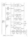
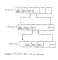
processing subsequent graphic orders to draw the primitive. - A comparison with a prior art implementation is summarised in Fig. 2.
- In the prior art IBM 5080 graphics workstation implementation, the traversal process is done via the display list program. Such a program consists of graphic orders which are interpreted by the display processor.
- In the implementation discussed below, a new interface is introduced between the host program and the display processor, and the transversal process is implemented at the machine language level. This results in the saving of workstation memory storage and in improved performance.
- As an example, the prior art method of attribute binding for Polymarker (testing for invisibility, highlighting, and detectability; and satisfaction of the choices of the colour, marker size, and marker type) required more than 50 bytes of user program memory. The new implementation of the same function, on the other hand, requires only four bytes.
- The advantages of this system over the prior art are
- 1. more efficient use of workstation memory for user programs;
- 2. Fewer lines of code in display program reduces the link transmission time from the host to workstation.
- 3. the machine level language implementation eliminates the two-level interpretation process.
- These advantages result in the saving of workstation memory storage and improved performance.
- The IBM 5080 Graphics System is used here to illustrate a preferred embodiment. (See IBM 5080
Model 2 Principles of Operation Document No.: GA23-2012-0). - The present invention will be described furhter by way of example with reference to examples of the prior art and an embodiment of the invention as illustrated in the accompanying drawings in which:
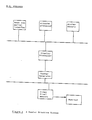
- Fig. 1 is a block diagram of a raster graphics system capable of performing the method of the present invention;
- Fig. 2 is a block diagram comparison of the method according to the present invention with a prior art method of performing traversal;
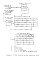
- Fig. 3 is a block diagram of a display processor suitable for use with the raster graphic system shown in Fig. 1;
- Fig. 4 shows an address pointer structure for a programmable character set description table;
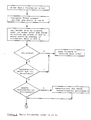
- Fig. 5 is a flow chart showing the improved method according to the present invention;
- Fig. 6, which consists of Figs. 6.1, 6.2 and 6.3 is a flow chart showing a specific example of the method according to the present invention with reference to a Polymarker graphics order;
- Fig. 7 is a block diagram showing an End primitive order;
- Fig. 8 is a schematic diagram showing an execute structure having several levels;
- Fig. 9 is a schematic diagram showing the execute structure as in Fig. 8 with indications of required storage of traversal state information between structures;
- Fig. 10 is a schematic diagram of the structure of Fig. 8 showing a specific primitive "Polymarker"; and
- Fig. 11 is a schematic diagram of the structure as shown in Fig. 8 further including a new graphics order in accordance with the method of the present invention.
- Consider the raster graphics system in Fig. 1 which consists of the following major components:
- 1. Attachment Processor
- 2. Host Communication Serial Interface Processor
- 3. Display Processor
- 4. Hardware Rasteriser - Vector Generator
- 5. Video Pixel Memory
- 6. System Memory
- The following is a brief overview of the functions of the major components.
-
- * The attachment processor is a general purpose processor that has master control of the System. The attachment processor is responsible for servicing all attached Graphics I/O devices (except the light pen and display monitor).
* Coordinating the associated processing with the display processor.
* The attachment processor interfaces with the host via serial interface.
- The serial interface provides the serial interface of the system to the host.
- The DP is responsible for executing the graphics orders in the display storage program residing in the system memory and is mainly concerned with the generation of the image that will appear on the display monitor. It has the following functions:
* Decoding graphics orders and executing non-drawing orders; e.g. book keeping and control.
* Performs the transformation and clipping function for the geometric primitives: lines, characters, polygons, etc.
* Preparing the following geometric objects for display: lines, characters, markers, filled polygons, by preprocessing and feeding the data to the vector generator and video pixel memory. - Vector generator is a hardware implementation of the Bresenham line generating algorithm, which takes the end points of a vector (line) as input, and generates pixels in the video pixel memory as output for display.
- Video pixel memory consists of 8 1k by 1k bit planes, which supports 256 colours simultaneously via colour look-up tables. The image stored here will be displayed on the monitor.
- For the logical data flow of the graphics system, see Fig. 1.
- 1. The Application Program is loaded from the host via the serial interface to the System Memory;
- 2. The attachment processor preprocesses the data (depending on the work required), then interrupts the DP;
- 3. The display processor then processes the data;
- 4. The data is then passed to the VPM for display directly or via the vector generator.
- The Display Processor is a microprogrammed system. It fetches the data from the memory and sends the data out to the raster display via the Vector Generator, which is a rasteriser. It takes the line segment end points coordinates as input, and generates pixels in the video pixel memory.
- The main ingredients of the system (see Fig. 3) are:
- 1. sequencer, e.g. AMD2910A;
- 2. 72-bit wide writable control store;
- 3. 16-bit ALU, e.g. 4 bit slice AMD2903;
- 4. a 16×16 multiplier with 32-bit accumulator, e.g. WTL2010;
- 5. a 32-bit barrel shifter;
- 6. a clipper (for checking revival accept/reject);
- 7. 4k × 16 scratch ram;
- 8. logic for microcode next address coming from the content of scratch pad ram registers - indexed addressing.
- The microprogram is stored in the writable control store.
- The interface between the host program and the display processor is defined in the 256 graphics interface registers (see section on communication area for detail) in the display processor scratch pad ram. (See Fig. 3).
- For each of the six drawing primitives line, marker, annotation, text, geometric text, polygon, and pixel array, the attributes (such as colour, line width, line type for line) are contained in the graphics interface registers; which also contain the view, global, and modelling transformation matrices applying to the primitive.
- The attribute binding of a drawing primitive is implemented in the display processor microcode using the data from the 256 graphics interface registers (see the section on polymarkers).
- The usage of the graphics interface registers in a graphics workstation embodying the present invention is as follows:
- 0-1 Pick interrupt address. The DP will simulate a branch and link to this address whenever a primitive is detected and GIR 188, bit 0 is set. This will probably be performed within the tail order.
- 2 - Page containing head and tail of picked element.
- 3 - Offset in page of begin
primitive order + 4. - 4 - Offset in page of end
primitive order + 2. - 5 Not currently used.
- 6-7 Pick Identifier. An arbitrary 32 bit number which is returned to the application when a primitive is picked.
- 8 Element counter. This GIR is set to zero when traversal of a structure is started and incremented by each structure element. This includes attribute setting functions as well as primitives. The value in this register will be returned to the application when a primitive is picked.
- 9-10 Structure Identifier. Contains an arbitrary 32 bit number which is the application specified identifier of the structure being traversed.
- 11 Structure normalisation scale factor. Signed 15 bit integer. (Sxxx xxxx xxxx xxxx).
- 12 X translation to centre of structure extent. (Sxxx.xxxx xxxx xxxx)
- 13 Scale factor for × translation in GIR 12. Signed 15 bit integer. (Sxxx xxxx xxxx xxxx)
- 14 Y translation to centre of structure extent (Sxxx.xxxx xxxx xxxx).
- 15 Z translation to centre of structure extent (Sxxx.xxxx xxxx xxxx).
- 17 Scale factor for z translation in
GIR 16. Singed 15 bit integer. (Sxxx xxxx xxxx xxxx). - 18 Matrix control Flags
- Bit 0 - Set to 1 if global or view matrix has been changed. Therefore, recompute Global * View and save.
- Bit 1 - Set to 1 if Local transformation has changed. Therefore, recompute Normalisation * Local * saved result of Global * View.
- Bit 2 - Set if recalculation of 5080 TCF parameters is needed.
- Bits 3-15 Reserved.
- 19 Text Attribute Control Flags. Used to optimise the processing required by geometric text primitives.
- Bit 0 - Set to 1 if character height, expansion factor, up vector precision or spacing has changed.
- Bit 1 - Set to 1 if font has changed.
- 20 Attribute Source Flags. Identifies whether the individual or bundled attribute value is to be used when rendering the corresponding primitive. (0=individual,1=bundled).
- Bit 0 - Polyline Colour Index
- Bit 1 - polyline Line Width
- Bit 2 - Polyline Line Type
- Bit 3 - Polymarker Colour Index
- Bit 4 - Polymarker Size
- Bit 5 - Polymarker Type
- Bit 6 - Interior Colour Index
- Bit 7 - Interior Style
- Bit 8 - Interior Style Index
- Bit 9 - Edge Flag
- Bit 10 - Edge Colour Index
- Bit 11 - Edge Linetype
- Bit 12 - Edge Linewidth. (not supported)
- 21 Attribute Source Flags (Continued)
- Bit 0 - Text Precision
- Bit 1 - Text Colour Index
- Bit 2 - Text Font
- Bit 3 - Character Expansion Factor
- Bit 4 - Character Spacing
- 22 Highlighting Colour Index. A value in the range 0-255 which indicates the colour table index which is to be used to draw a primitive when highlighting is on.
- 23 Polyline Individual Colour Index. A value in the range 0-255 which indicates the colour table index which is to be used when drawing polylines if the corresponding ASF is set to individual.
- 24 Polyline Individual Line Width. The width is specified as a 12 bit binary number. Its meaning is identical to the 'w' bits in the attribute register 21-22. This value will only be used to draw polylines when the corresponding ASF is set to individual.
- 25 Polyline Individual Line Type. This value is specified as a number in the range 0-15. This is identical to the 't' bits in
attribute register 2. - 26 Polyline Individual Line End Control. This value is specified in bits 14-15. These bits have the same meaning as the 'e' bits in attribute register 22.
X'0010' = Flat end
X'0020' = Round end
X'0030' = Square end - 27 Polyline Bundled Colour Index. A value in the range 0-255 which indicates the colour table index which is to be used when drawing polylines if the corresponding ASF is set to bundled.
- 28 Polyline Bundled Line Width. The width is specified as a 12 bit binary number. Its meaning is identical to the 'w' bits in the attribute registers 21-22. This value will only be used to draw polylines when the corresponding ASF is set to bundled.
- 30 Polymarker Individual Colour Index. A value in the range 0-255 which indicates the the colour table index which is to be used when drawing polymarkers if the corresponding ASF is set to individual.
- 31 Polymarker Individual Marker Size. The size of a polymarker is specified in terms of a Marker character set identifier. The value contained in this register will have the same meaning as attribute register 20. The following values may be specified:
X'0004' = Basic size
X'0005' = Large size
X'0006' = Small size
X'0007' = Medium size - 32 Polymarker Individual Marker Type. This register will specify the type of marker to be used on succeeding polymarker primitives. This register has the same interpretation as the
attribute register 1. - 33 Polymarker Bundled Colour Index. The value contained in this register has the same meaning as GIR 30 except it is only used when the ASF for this attributes is set to bundled.
- 34 Polymarker Bundled Marker Size. The value contained in this register has the same meaning as GIR 31 except it is only used when the ASF for this attributes is set to bundled.
- 35 Polymarker Bundled Marker Type. The value contained in this register has the same meaning as GIR 32 except it is only used when the ASF for this attributes is set to bundled.
- 36 Interior Individual Colour Index. This register will contain a value in the range 0-255 which indicates the colour table index which is to be used when filling the interior of a polygon or drawing the edge of a hollow polygon with edge off. This register is only used if the corresponding ASF is set to individual.
- 37 Interior Individual Style. The content of this register will indicate how the interior of the polygon is to be drawn. Valid values include:
0 = Hollow (no fill,draw edge in interior colour if edge off)
1 = Solid, fill with solid colour
2 = Fill with user defined pattern from pattern table
3 = Fill with hatch pattern from hatch table
This register is used for the interior style only if the interior style ASF is set to individual. - 38 Interior Individual Style Index.
If the interior style is either pattern (3) or hatch (4) then this register will contain the index of the entry in the corresponding table that is to be used to fill the polygon. The addresses of the pattern and hatch table are contained in other GIR's. This register is used only when the corresponding ASF is set to individual. - 39 Interior Bundled Colour Index.
This register has the same meaning and use as GIR 36 except that this one is only used when the ASF is set to bundled. - 40 Interior Bundled Style.
This register has the same meaning and use as GIR 37 except that this one is only used when the ASF is set to bundled. - 41 Interior Bundled Style Index.
This register has the same meaning and use as GIR 38 except that this one is only used when the ASF is set to bundled. - 42 Edge Individual Flag.
Indicates whether the edge of a polygon is to be drawn or not. (0=OFF,1=ON). - 43 Edge Individual Colour Index.
This register will contain a value in the range 0-255 which indicates the colour table index which is to be used when drawing the edge of a polygon and when the edge flag is set to ON. This register is only used if the corresponding ASF is set to individual. - 44 Edge Individual Linetype.
This register will contain a value in the range 0-15 which identifies the line style that the edge of the polygon is to be drawn in if the edge flag is on. This value is identical to the 't' bits in theattribute register 2. This value will only be used when the corresponding ASF is set to individual. - 45 Edge Individual Linewidth.
Not used currently, reserved for future use. - 46 Edge Bundled Flag.
This register has the same meaning and use as GIR 42 except that this one is only used when the ASF is set to bundled. - 47 Edge Bundled Colour Index.
This register has the same meaning and use as GIR 43 except that this one is only used when the ASF is set to bundled. - 48 Edge Bundled Linetype.
This register has the same meaning and use as GIR 44 except that this one is only used when the ASF is set to bundled. - 49 Edge Bundled Linewidth.
Not used currently, reserved for future use. - 50 Text Precision (Individual).
This register determines which of the text attributes are to be applied when drawing a geometric text primitive. The valid values and their meaning for annotation and geometric text is shown below:
- 51 Text Colour (Individual).
This register will contain a value in the range 0-255 which specifies the colour table index that is to be used for drawing Annotation or Geometric text primitives. This register is only used when the corresponding ASF is set to individual. - 52 Text Font (Individual).
This value contains an address of a DLB location which contains the row offset into the font address table. This register is used in conjunction with the Character Set Identifier that is specified on Geometric text elements. See Fig. 4 for more information. This value is only used when the corresponding ASF is set to individual. - 53 Character Expansion Factor (Individual).
This register contains a value which represents the deviation of the width of the character from that defined in the PCS (Programmable Character Set). This value is multiplied times the PCS nominal width to obtain the actual character width. The value in this register will be in the form S.xxxxxxxxxxxxxxx. This register is only used when the corresponding ASF (Attribute Source Flag) is set to individual. - 54 Character Expansion Scale Factor (Individual).
This register specifies the exponent for the value in register 53 and is only used when the Character Expansion Factor ASF is set to individual. - 55 Character Spacing (Individual).
This register contains a value which defines the amount of additional space to be placed between characters. The value is multiplied times the character height to obtain the spacing between characters. The actual width of a character is then added to the actual spacing to obtain the spacing to be given to the hardware. The value in this register will be in the form S.xxxxxxxxxxxxxxx. This register will only be used when the corresponding ASF is set to individual. - 56 Character Spacing Scale Factor (Individual).
This register specifies the exponent for the value in register 55 and is only used when the Character Spacing ASF is set to individual. - 57 Text Height.
This register defines the height of geometric text primitives. The value will be specified in the form S.xxxxxxxxxxxxxxx. - 58 Text Height Scale Factor.
This register specifies the exponent for the value in register 67. - 59 Annotation Height Scale Factor.
This register specifies the height to be used in drawing succeeding annotation primitives. The value specified will be the same as the CSIDs for the 4 hardware character heights. They are:
X'0004' = Basic size
X'0005' = Large size
X'0006' = Small size
X'0007' = Medium size - 60 Character Up Vector (Sine).
This register will contain the sine of the angle formed between the character up vector and the X-axis of the text coordinate system. The format of the number will be Sx.xxxxxxxxxxxxxx. - 61 Character Up Vector (Cosine).
This register will contain the cosine of the angle formed between the character up vector and the X-axis of the text coordinate system. The format of the number will be Sx.xxxxxxxxxxxxxx. - 62 Text Alignment.
This register specifies the alignment of text primitives relative to their position. The format of the value in this register is:- Byte 0 - Vertical Alignment
- Bit 0 - Normal
- Bit 1 - Top
- Bit 2 - Cap
- Bit 3 - Half
- Bit 4 - Base
- Bit 5 - Bottom
- Byte 1 - Horizontal Alignment
- Bit 8 - Normal
- Bit 9 - Left
- Bit 10- Center
- Bit 11- Right
- Byte 0 - Vertical Alignment
- 63 Text Path.
This register specifies the direction in which succeeding characters in an annotation or geometric text primitive are to be positioned relative to the previous character. This value has the same format as attribute 'iiii' bits. Valid values for this register are:
X'0000' = Right
X'0040' = Up
X'0080' = Left
X'00C0' = Down - 64 Text Precision (Bundled).
This register has the same meaning as GIR 50 except that it is only used when the corresponding ASF is set to bundled. - 65 Text Colour (bundled).
This register has the same meaning as GIR 51 except that it is only used when the corresponding ASF is set to bundled. - 66 Text Font (Bundled).
This register has the same meaning asGIR 52 except that is only used when the corresponding ASF is set to bundled. - 67 Character Expansion Factor (Bundled).
This register has the same meaning as GIR 53 except that it is only used when the corresponding ASF is set to bundled. - 68 Character Expansion Factor Scale Factor (Bundled).
This register has the same meaning as GIR 54 except that it is only used when the corresponding ASF is set to bundled. - 69 Character Spacing (Bundled).
This register has the same meaning as GIR 55 except that it is only used when the corresponding ASF is set to bundled. - 70 Character Spacing Scale Factor (Bundled).
This register has the same meaning as GIR 56 except that it is only used when the corresponding ASF is set to bundled. - 71 Last used character set id.
This register will be used by the microcode when processing a geometric text primitive to determine whether the character set id specified is the same as the previous geometric text primitive. The DLB program will clear this register to force the microcode to resolve the text attributes. - 72-81 Text Attribute Composite Matrix.
These registers will contain a 3×3 matrix which will be used to achieve the current set of text attributes. This matrix contains the accumulation of Height, Expansion Factor, and Up vector. The order of the values in this are as follows:- 72 - M11
- 73 - M12
- 74 - M13
- 75 - M21
- 76 - M22
- 77 - M23
- 78 - M31
- 79 - M32
- 80 - M33
- 81 - Scale factor
- 82-97 Global Modelling Transformation Matrix.
These registers will contain the current global modelling transformation. The format of the matrix will be:
Matrix elements M11-M33 will be in the form S.xxx xxxx xxxx xxxx.
Matrix elements M41-M43 will be in the form Sxxx.xxxx xxxx xxxx.
All scale factors will be signed 15 bit integers. (Sxxx xxxx xxxx xxxx).- 82 - M11
- 83 - M12
- 84 - M13
- 85 - M21
- 86 - M22
- 87 - M23
- 88 - M31
- 89 - M32
- 90 - M33
- 91 - Scale factor for M11-M33 (-512 if identity)
- 92 - M41
- 93 - Scale factor for M41
- 94 - M42
- 95 - Scale factor for M42
- 96 - M43
- 97 - Scale factor for M43
- 98-113 Local Modelling Transformation Matrix.
These registers contain the local modelling transformation matrix. The order of the term in the matrix will be the same as in the global modelling transformation matrix. - 114-129 View Transformation Matrix.
These register contain the viewing transformation matrix. The order of the terms in the matrix will be the same as in the global modelling transformation matrix. - 130-135 Clipping Boundaries.
These registers will contain the current window. The format of these values will be Sxxx.xxxxxxxxxxxx. - 136 Viewpoint.
This register will contain the current viewpoint for perspective. The format of this value will be Sxxx.xxxxxxxxxxxx. - 137-152 Result of Global * View.
These registers will contain the result of concatenating the Global transformation time the View transformation. The order of the terms of this matrix will be the same as the global modelling transformation matrix. - 153-168 Result of Normalisation * Local * Global * View.
These registers will contain the concatenation of the four matrices. The order of the terms of this matrix will be the same as the global modelling transformation matrix. - 169 Number of class names currently in class set and Pick Inclusion Filter.
This register will be incremented each time a bit is turned on in the current set that is also in the pick inclusion filter. It will be decremented each time a bit is turned off in the pick set that is also in the inclusion pick filter. If this register is greater than zero and GIR 170 is equal to zero then detectability is on. - 170 Number of class names currently in class set and Pick Exclusion Filter.
This register will be incremented each time a bit is turned on in the current set that is also in the pick exclusion filter. It will be decremented each time a bit is turned off in the pick set that is also in the exclusion pick filter. If this register is greater than zero then detectability is off. - 171 Number of class names currently in class set and Highlighting Inclusion Filter.
This register will be incremented each time a bit is turned on in the current set that is also in the highlighting inclusion filter. It will be decremented each time a bit is turned off in the pick set that is also in the inclusion highlighting filter. If this register is greater than zero and GIR 172 is equal to zero then highlighting is on. - 172 Number of class names currently in class set and Highlighting Exclusion Filter.
This register will be incremented each time a bit is turned on in the current set that is also in the highlighting exclusion filter. It will be decremented each time a bit is turned off in the pick set that is also in the exclusion highlighting filter. If this register is greater than zero then highlighting is off. - 173 Number of class names currently in class set and Invisibility Inclusion Filter.
This register will be incremented each time a bit is turned on in the current set that is also in the invisibility inclusion filter. It will be decremented each time a bit is turned off in the pick set that is also in the invisibility inclusion filter. If this register is greater than zero and GIR 174 is equal to zero then visibility is turned off. - 174 Number of class names currently in class set and Invisibility Exclusion Filter.
This register will be incremented each time a bit is turned on in the current set that is also in the invisibility exclusion filter. It will be decremented each time a bit is turned off in the pick set that is also in the invisibility exclusion filter. If this register is greater than zero then visibility is turned on. - 175-190 Class set (1 bit / class name - max 256 class names)
This field contains one bit for each supported class name. The corresponding bit is turned on when a class name is added to the set and turned off when removed from the set. - 191 Control flags.
Bits 0-3 in this register will be set according to the class set counts maintained above.- Bit 0 - Detectability is on if set.
- Bit 1 - Highlighting is on if set.
- Bit 2 - Invisible if on.
- Bit 3 - Pick Correlation-Only Mode. This bit is set to allow the microcode to skip primitives which are not detectable or to optimise the correlation process.
- 192 Pattern/Hatch Table Page Number.
This register will contain the page number which contains the pattern and hatch tables and is used in conjunction with GIRs 193 and 194 to load pattern/hatch table entries. This register is set at initialisation and is never changed. - 193 Pattern Table Address.
Contains the address of the pattern table address. Each entry of the table will contain 256 bytes of colour table indices. When the interior style is set to pattern, the interior style index will be used to index into this table to obtain the pattern to load into the hardware for filling succeeding polygons. The pattern table will always be in page 0. - 194 Hatch Table Address.
Contains the address of the hatch table. When the interior style is set to hatch, the interior style index will be used as an index into this table. Each entry will contain 32 bytes in which each bit corresponds to a position in a 16 by 16 pattern. (row order). If a bit is on, the pattern cell should be filled with the interior colour index. Otherwise, it should be filled with 0. The microcode will construct this pattern from the hatch table entry and then load it into hardware. - 195 Current Pattern/Hatch Table Entry Address.
Contains the address of the currently loaded pattern/hatch table entry. This issued by the microcode to eliminate loading a pattern which is already loaded. This field will be cleared when the DLB program wants to force reloading of a pattern. If the requested pattern/hatch table entry address does not match this register then the pattern/hatch must be reloaded. - 196 Current Interior Colour of Loaded Hatch.
This field will contain the interior colour index that was used to construct the hatch pattern that is now loaded in the hardware. It will used in conjunction with GIR 195 to eliminate reloading of a hatch pattern that is already loaded. If the address in GIR 195 matches the requested hatch table entry address and the contents of this register match the effective interior colour index then no new pattern load is required. - 197 Pattern/Hatch Maximum Table Entries.
The following fields are used by the microcode to save information that was calculated during the processing of a geometric text primitive that may be used on succeeding geometric text primitives. - 198 Effective CSID for geometric text.
- 199 Effective Normal Height (PCS Q).
- 200 Effective Nominal Width
- 201 Effective Cap to Top Spacing
- 202 Effective Bottom to Base Spacing
- 203 Effective Spacing. Calculated by Microcode
- 204 Effective Path. Calculated by Microcode
- 224-239 Work area for matrix calculations.
The contents of these registers are not preserved across Begin/End Primitive orders. - 240-255 Control Flags for Load attribute registers.
These registers contain 1 bit for each graphics interface register. These registers will be cleared each time traversal is started. When a load attribute register is encountered, the control bits for the specified registers will be examined. If the bit is zero, the contents of the registers will be pushed prior to loading the new value. The control bits will also be set at this time. If the control bits were already one, the contents of the registers will not be stacked. - As an example of how the communication area described earlier is used, we will now discuss the Begin Polymarker and the End Primitive orders implemented on the IBM 5080
model 2. These orders are two of seven new orders implemented to support the six drawing primitives available to applications using the IBM graPHIGS™ Program product. In addition to the Begin Polymarker order, orders have been defined to support the drawing of polylines, annotation text, geometric text, polygons, and pixel blocks. A generalised flowchart of the processing performed by any of the six Begin Primitive orders is shown in Fig. 5. This section describes the Begin Polymarker and the End PHIGS Primitive orders in detail to give one example of how the previously described PHIGS communication area is used. - The IBM graPHIGS program product will generate a graphics program in response to its invocation by the application in control. If the application requests the generation of polymarkers on the screen, a portion of the generated datastream will appear as follows:
.
.
.
Begin Polymarker opcode
Length of the polymarker data
Polymarker data (consisting of orders to draw the polymarkers)
End PHIGS primitive opcode
(graphic orders for next PHIGS primitive)
.
.
. - The orders in the data stream prior to the Begin Polymarker order load the information it needs into the PHIGS communication area. The data word immediately following the Begin Polymarker opcode gives the number of bytes in the polymarker data.
- When the Begin Polymarker order is executed, the following actions will be taken:
Example of use of communication area 18: - 1. Calculate and store 'pick path' data (such as element number, address of the primitive, etc.) used later if a pick occurs.
- 2. If the invisibility bit in GIR 191 is one, the length data is used to jump forward past the End Primitive opcode to execute the graphics orders for the next primitive.
- 3. If the 'correlation-only' mode bit in GIR 191 is on and the detectable bit in GIR 191 is off, jump forward past the End Primitive opcode to execute the graphics orders for the next primitive.
- 4. If any of the three matrix control flag bits in GIR 18 are on, update the transformation environment (recompute the transformation matrix and related variables based on the matrices defined in the communication area).
- 5. Set the appropriate colour for the polymarkers about to be drawn. This data is obtained by examining the flags in GIRs 20 and 191, and then using the appropriate colour from GIRs 22, 30, or 33.
- 6. Set the appropriate marker size for the polymarkers about to be drawn. This data is obtained by examining the flags in GIR 20, and then using the appropriate marker size from GIRs 31 or 34.
- 7. Set the appropriate markertype for the polymarkers about to be drawn. This data is obtained by examining the flags in GIR 20, and then using the appropriate marker type from GIRs 32 or 35.
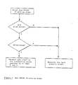
- These actions are illustrated in the flowchart in Fig. 6.
- When the End PHIGS Primitive order is executed, the following actions are taken:
- 1. If no pick occurred during the drawing of the polymarkers, or if the detectable flag in register 191 was not set, execution continues with the graphics orders for the next primitive.
- 2. If a pick occurred and the detectable flag in register 191 was set, a "branch and link" is done using the address in registers 0 and 1 (
registers 0 and 1 were previously loaded with the address of a "pick handler" subroutine). - These actions are illustrated in the flowchart in Fig. 7.
- The registers in the communication area may be separated into 5 groups:
polymarker attributes registers 23-29
polymarker attributes registers 30-35
area-fill interior attributes registers 36-41
area-fill interior attributes registers 42-49
text attributes registers 50-81 - In addition to this, there are data for the transformation matrices associated with the drawing primitives.
- Each of the drawing primitives has a set of attribute registers associated with it. For example, the following registers pertain to Polymarkers:
- 1. bundled attributes
reg 30 polymarker bundled colour index
reg 31 polymarker bundled marker size
reg 32 polymarker bundled marker type - 2. individual attributes
reg 33 polymarker individual colour index
reg 34 polymarker individual marker size
reg 35 polymarker individual marker type - For each attribute, the possible source is from the bundle table or individual registers depending on the bit corresponding to that attribute in the ASF. The contents of registers 20-21 Attribute Source Flags (ASF) will determine which registers (individual or bundled) will apply at the time of processing the polymarker data.
- There is a stack for storing the attribute registers data for processing the 'Execute Structure" structure element. (see Figs. 8 and 9).
- In Fig. 8, structure A called structure B, which can alter the state of the device, e.g. the attribute registers associated with Polymarker.
- When an "Execute Structure" structure element is executed, some of the registers associated with the "calling" structure will be saved on the stack; e.g. attribute registers, transformation matrix, ASF, etc.
- When an "End of a Structure" is executed (return from a "called" structure), the stack is popped, and the attribute registers will be restored (see Fig. 9). This implementation will cause many registers contents to be saved (on the stack) and popped (from the stack). As shown by the example in Fig. 10, the only registers changed are associated with polymarker, but all the other registers must also be saved and popped, which is time-consuming.
- To eliminate the unnecessary stacking of the registers when "Execute Structure" is processed, 16 registers (240-255) are used as control flags to selectively save registers onto the stack.
- These registers contain 1 bit for each graphics interface register. These registers will be cleared each time traversal of a PHIGS structure is started. When a load PHIGS attribute register is encountered, the control bits for the specified registers will be examined. If the bit is zero, the contents of the registers will be pushed prior to loading the new value. The control bits will also be set at this time. If the control bits were already one, the contents of the registers will not be stacked.
- At the end of a root structure, there will a 'pop' to clean up the stack.
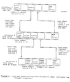
- The Polymarker attribute registers individual colour index (register 30) will be used as a example (Fig. 11).
- If the bit is zero, then the display processor saves the corresponding colour register on the stack, processes the structure element and set the corresponding bit of the stack control flags register to 1.
- If the bit is one, then display processor processes the structure element, without putting anything on the stack.
- When the 'return from an executed structure' is processed, the stack will be popped until the display processor encounters a stack mark.
-
- 1. All control bits of registers 240-255 set to zero initially;
- 2. When the conditional load and push polymarker individual colour registers with 'colour1' (will be denoted by conditional loading colour below) is processed; because the (corresponding) control bit is 0, the existing colour is saved on the stack, and the control bit is set to 1;
- 3. When the 'execute structure' B is processed, a stack marker is put on the stack (as the limit of stack popping operation), the contents of registers 240-255 (control flags) will be saved on the stack; and all control bits of registers 240-255 are set to zero.
- 4. When the conditional loading colour 'colour2' is processed, 'colour1' is saved on the stack, and the control bit is set to 1;
- 5. When the 'execute structure' B is processed, a stack marker is put on the stack (as the limit of stack popping operation), the contents of registers 240-255 (control flags) will be saved on the stack; and all control bits of registers 240-255 are set to zero;
- 6. When the conditional loading colour 'colour3' is processed, 'colour2' is saved on the stack, and the control bit is set to 1;
- 7. When the conditional loading colour 'colour4' is processed, because the (corresponding) control bit is 1, the existing colour 'colour3' is not saved on the stack;
- 8. When the 'end of structure' C is processed, the stack is popped (to the stack marker). The contents of registers 240-255 (control flags corresponding to structure B) are restored, and so is 'colour2';
- 9. When the 'end of structure' B is processed, the stack is popped (to the stack marker). The contents of registers 140-255 (control flags corresponding to structure B) are restored, and so is the 'colour1'.(See Fig. 11).
- While the invention has been particularly shown and described with reference to a preferred embodiment thereof, it will be understood by those skilled in the art that various changes in form and detail may be made therein without departing from the scope of the appended claims.
Claims (7)
calculating pick data for a predetermined primitive;
testing the primitive for invisibility;
exiting to a next graphics order if the invisibility test is true;
testing the primitive for detectability;
exiting to a next graphics order if the detectability test is false when traversal is being performed for pick correlation purposes;
determining whether a transformation environment update is required;
recalculating the transformation environment is required;
binding display attributes for the primitive; and
processing subsequent graphic orders to draw the primitive.
determining whether a highlight attribute is to be used with the primitive; and
loading a colour register with a highlight colour for the primitive.
determining whether to use a bundle colour if highlighting is not used; and
loading the colour register with a bundle colour if it is determined that the bundle colour is to be used; else
loading the colour register with an individual colour if it is determined that the bundle is not be used.
determining whether a bundle marker type is to be used with the primitive;
loading a marker type from the bundle table if the bundle marker type is to be used;
loading a marker type from an individual source is the bundle marker type is not to be used;
determining whether a bundle marker size is to be used;
loading a marker size from the bundle table is the bundle marker size is to be used; and
loading a marker size from an individual source if the bundle marker is not to be used.
selectively storing traversal state information based upon condition of flags representing storage state of information contained in a plurality of graphics interface registers.
determining from an examination of the flags which general interface registers have been previously stored; and
storing only those additional general interface register contents required for traversal of a current primitive which have not been previously stored.
setting a flag on corresponding to a predetermined graphics interface register when the contents of the graphics interface register containing some portion of the traversal state information is stored.
Applications Claiming Priority (2)
| Application Number | Priority Date | Filing Date | Title |
|---|---|---|---|
| US06/912,876 US4870599A (en) | 1986-09-26 | 1986-09-26 | Traversal method for a graphics display system |
| US912876 | 1986-09-26 |
Publications (2)
| Publication Number | Publication Date |
|---|---|
| EP0261391A2 true EP0261391A2 (en) | 1988-03-30 |
| EP0261391A3 EP0261391A3 (en) | 1990-07-18 |
Family
ID=25432607
Family Applications (1)
| Application Number | Title | Priority Date | Filing Date |
|---|---|---|---|
| EP87111956A Withdrawn EP0261391A3 (en) | 1986-09-26 | 1987-08-18 | Method of traversal of primitives in a graphics display system |
Country Status (3)
| Country | Link |
|---|---|
| US (1) | US4870599A (en) |
| EP (1) | EP0261391A3 (en) |
| JP (1) | JPH0727570B2 (en) |
Families Citing this family (11)
| Publication number | Priority date | Publication date | Assignee | Title |
|---|---|---|---|---|
| JPH01181163A (en) * | 1988-01-13 | 1989-07-19 | Seiko Instr & Electron Ltd | Graphic display system |
| US7382929B2 (en) | 1989-05-22 | 2008-06-03 | Pixel Instruments Corporation | Spatial scan replication circuit |
| AU5824690A (en) * | 1989-06-02 | 1991-01-07 | Atari Corporation | System and method for video display object detection |
| US5255359A (en) * | 1989-10-23 | 1993-10-19 | International Business Machines Corporation | Picking function for a pipeline graphics system using hierarchical graphics structures |
| JPH0797413B2 (en) * | 1991-05-16 | 1995-10-18 | インターナショナル・ビジネス・マシーンズ・コーポレイション | Pick method and apparatus in graphics system |
| DE69131251T2 (en) * | 1991-08-15 | 1999-12-09 | Ibm | System and method for processing data representing stored images |
| DE69127554T2 (en) * | 1991-10-10 | 1998-01-08 | Hewlett Packard Co | INTERPRETATION OF THE IMAGE POSITION IN A GRAPHIC SYSTEM. |
| US5289576A (en) * | 1992-03-12 | 1994-02-22 | International Business Machines Corporation | Attribute filter for computer graphics applications |
| US5430870A (en) * | 1992-10-13 | 1995-07-04 | Sun Microsystems, Inc. | Saving and restoring traversal state attributes of a directed acyclic graph structure network for a parent structure when it invokes a child structure for traversal |
| US5748946A (en) * | 1995-02-17 | 1998-05-05 | International Business Machines Corporation | Method and apparatus for improved graphics picking using auxiliary buffer information |
| US6320596B1 (en) | 1999-02-24 | 2001-11-20 | Intel Corporation | Processing polygon strips |
Family Cites Families (6)
| Publication number | Priority date | Publication date | Assignee | Title |
|---|---|---|---|---|
| JPS57190995A (en) * | 1981-05-20 | 1982-11-24 | Mitsubishi Electric Corp | Display indicator |
| US4489389A (en) * | 1981-10-02 | 1984-12-18 | Harris Corporation | Real time video perspective digital map display |
| US4506343A (en) * | 1982-05-17 | 1985-03-19 | International Business Machines Corporation | Column layout reference area display management |
| US4484187A (en) * | 1982-06-25 | 1984-11-20 | At&T Bell Laboratories | Video overlay system having interactive color addressing |
| US4475104A (en) * | 1983-01-17 | 1984-10-02 | Lexidata Corporation | Three-dimensional display system |
| US4665555A (en) * | 1985-03-11 | 1987-05-12 | Alpharel Incorporated | Computer based drawing management system |
-
1986
- 1986-09-26 US US06/912,876 patent/US4870599A/en not_active Expired - Fee Related
-
1987
- 1987-08-18 EP EP87111956A patent/EP0261391A3/en not_active Withdrawn
- 1987-08-20 JP JP62205344A patent/JPH0727570B2/en not_active Expired - Lifetime
Non-Patent Citations (1)
| Title |
|---|
| International Symposium on New Directions in Computing, Trondheim, August 12-14, 1985, pages 371-376, IEEE, New York, US; F. DEVAI: "A digital signal processor architecture for real-time image synthesis". * |
Also Published As
| Publication number | Publication date |
|---|---|
| EP0261391A3 (en) | 1990-07-18 |
| JPH0727570B2 (en) | 1995-03-29 |
| US4870599A (en) | 1989-09-26 |
| JPS6385989A (en) | 1988-04-16 |
Similar Documents
| Publication | Publication Date | Title |
|---|---|---|
| US4821209A (en) | Data transformation and clipping in a graphics display system | |
| US4697178A (en) | Computer graphics system for real-time calculation and display of the perspective view of three-dimensional scenes | |
| KR100597879B1 (en) | Method and apparatus for building rasterized lines of bitmap data to be printed using a piecewise-linear direct memor access addressing mode of retrieving bitmap data line segments | |
| US5021974A (en) | Method for updating a display bitmap with a character string or the like | |
| US4679041A (en) | High speed Z-buffer with dynamic random access memory | |
| JP4756937B2 (en) | How to draw graphic objects | |
| US5371514A (en) | Method and apparatus for determining the drawing primitives that are visible in a pick aperture of a graphics system | |
| EP0261391A2 (en) | Method of traversal of primitives in a graphics display system | |
| US5877779A (en) | Method and apparatus for efficient rendering of three-dimensional scenes | |
| WO2000019377B1 (en) | Graphics processor with deferred shading | |
| EP0316144B1 (en) | Method and apparatus for classifying graphics segments to facilitate pick and display operation | |
| US6121974A (en) | Priority storage system for fast memory devices | |
| US4811241A (en) | Clipping of fixed character strings in a graphics system | |
| US5295234A (en) | Apparatus for displaying a three dimensional object which appears substantially the same in different display directions by modifying stored image data by a scale factor | |
| JPH0776987B2 (en) | Graphic conversion method in graphic display system | |
| EP0095536B1 (en) | The representation of character images in a compact form for computer storage | |
| US6141020A (en) | Opposing directional fill calculators in a graphics processor | |
| US7136068B1 (en) | Texture cache for a computer graphics accelerator | |
| EP0356262B1 (en) | Image processing apparatus | |
| JPH01125234A (en) | Patch changing system | |
| Barrett et al. | Scan conversion algorithms for a cell organized raster display | |
| US5163129A (en) | Method for expediting the rendering of figures in a move-draw language | |
| KR930000179B1 (en) | Letter printing system for dot metrix printer | |
| EP0325409A2 (en) | Character generation | |
| JP2835056B2 (en) | High quality character pattern generation method |
Legal Events
| Date | Code | Title | Description |
|---|---|---|---|
| PUAI | Public reference made under article 153(3) epc to a published international application that has entered the european phase |
Free format text: ORIGINAL CODE: 0009012 |
|
| AK | Designated contracting states |
Kind code of ref document: A2 Designated state(s): DE FR GB IT |
|
| 17P | Request for examination filed |
Effective date: 19880729 |
|
| PUAL | Search report despatched |
Free format text: ORIGINAL CODE: 0009013 |
|
| AK | Designated contracting states |
Kind code of ref document: A3 Designated state(s): DE FR GB IT |
|
| 17Q | First examination report despatched |
Effective date: 19921223 |
|
| STAA | Information on the status of an ep patent application or granted ep patent |
Free format text: STATUS: THE APPLICATION HAS BEEN WITHDRAWN |
|
| 18W | Application withdrawn |
Withdrawal date: 19930408 |
|
| RIN1 | Information on inventor provided before grant (corrected) |
Inventor name: HEMPEL, BRUCE CARLTON Inventor name: LIANG, BOB CHAO-CHU Inventor name: LAIB, GREGORY DONALD |