EP0261094A2 - A hinge arrangement - Google Patents
A hinge arrangement Download PDFInfo
- Publication number
- EP0261094A2 EP0261094A2 EP87850281A EP87850281A EP0261094A2 EP 0261094 A2 EP0261094 A2 EP 0261094A2 EP 87850281 A EP87850281 A EP 87850281A EP 87850281 A EP87850281 A EP 87850281A EP 0261094 A2 EP0261094 A2 EP 0261094A2
- Authority
- EP
- European Patent Office
- Prior art keywords
- hinge
- elements
- panels
- panel
- arrangement according
- Prior art date
- Legal status (The legal status is an assumption and is not a legal conclusion. Google has not performed a legal analysis and makes no representation as to the accuracy of the status listed.)
- Granted
Links
Images


Classifications
-
- E—FIXED CONSTRUCTIONS
- E05—LOCKS; KEYS; WINDOW OR DOOR FITTINGS; SAFES
- E05D—HINGES OR SUSPENSION DEVICES FOR DOORS, WINDOWS OR WINGS
- E05D3/00—Hinges with pins
- E05D3/06—Hinges with pins with two or more pins
- E05D3/12—Hinges with pins with two or more pins with two parallel pins and one arm
-
- E—FIXED CONSTRUCTIONS
- E05—LOCKS; KEYS; WINDOW OR DOOR FITTINGS; SAFES
- E05Y—INDEXING SCHEME RELATING TO HINGES OR OTHER SUSPENSION DEVICES FOR DOORS, WINDOWS OR WINGS AND DEVICES FOR MOVING WINGS INTO OPEN OR CLOSED POSITION, CHECKS FOR WINGS AND WING FITTINGS NOT OTHERWISE PROVIDED FOR, CONCERNED WITH THE FUNCTIONING OF THE WING
- E05Y2900/00—Application of doors, windows, wings or fittings thereof
- E05Y2900/20—Application of doors, windows, wings or fittings thereof for furnitures, e.g. cabinets
-
- Y—GENERAL TAGGING OF NEW TECHNOLOGICAL DEVELOPMENTS; GENERAL TAGGING OF CROSS-SECTIONAL TECHNOLOGIES SPANNING OVER SEVERAL SECTIONS OF THE IPC; TECHNICAL SUBJECTS COVERED BY FORMER USPC CROSS-REFERENCE ART COLLECTIONS [XRACs] AND DIGESTS
- Y10—TECHNICAL SUBJECTS COVERED BY FORMER USPC
- Y10T—TECHNICAL SUBJECTS COVERED BY FORMER US CLASSIFICATION
- Y10T403/00—Joints and connections
- Y10T403/32—Articulated members
- Y10T403/32008—Plural distinct articulation axes
- Y10T403/32081—Parallel rotary
Definitions
- the present invention relates to a hinge arrangement for pivotally connecting a first element to a second element. More specifically, the invention relates to a hinge arrangement of the kind which, in order to function, requires at least one of the elements to present an internal cavity adjacent the hinge point this cavity being intended to co-act with a hinge member, such as a hinge pin or hinge arm, intended for holding the elements together.
- a hinge member such as a hinge pin or hinge arm
- the hinge arrangement or panel coupling can be used, with particular advantage, between two or more flat sheet-like elements which are connected together or to some other element, such as a wall or door frame.
- the present invention also relates to a portable panel display system or sign system which incorporates the inventive hinge arrangement and which comprises a multiple of panels placed in edge-to-edge relationship, each of which panels is preferably embraced, either fully or partially, with a number of edge strips, wherewith at least two mutually adjacent edge strips of respective panels or sheet-like elements are hinged together by means of one or more of said hinge arrangements.
- a hinge arrangement of this published application com strictlyprises a channelled, extruded aluminium section, wherein a first channel is intended to embrace one edge of a panel and a second channel is intended to co-act with an extruded nylon section, which functions as a connected or coupling member, such as a hinge pin.
- the hinge member is of elongated shape, having a circular part at each end thereof, which together with a pin is intended to coact with the channel in said extruded aluminium sections.
- Hinge arrangements which allow relative movements through 360° are also known to the art, however.
- An example of one such hinge arrangement is found in European Patent Application 8236224.5, publication number 0109466.
- the mutually opposing surfaces of the first and second elements are provided with mutually correspond ing serrations which are constantly in contact with one another as the two elements are swung.
- the two elements are held together at the mutually facing edge parts thereof by means of a stirrup-like device which is provided with bearing surfaces.
- Portable sign or display systems are also known for displaying so-called "blow-ups" which comprise extremely large enlargements of a photograph and which cannot be shown in their entirety on a single panel.
- Another technical problem is one of providing a hinge arrangement which may include solely one, separate member capable of being fitted readily to an edge part of a panel and which will provide an effective function in co-action with the panel, without needing to use specially designed tools.
- a further technical problem is one of providing a complete hinge arrangement comprising a sole separate part at low costs.
- the first element and/or the second element has the form of a panel which has a hollow tubular member provided along at least one edge surface thereof, or on two mutually opposite edge surfaces thereof, these tubular members having narrow slots formed therein and forming part of the inventive hinge arrangement.
- a technical problem will also be seen to exist in the provision of means which will enable a first bundle or stack of elements or panels to be connected to a second bundle or stack of elements or panels in a manner such that mutually adjacent panels of respective bundles or stacks can be extended simultaneously.
- each panel may well comprise a framework, a plate-like element folded or bent at its edges, or at least two mutually parallel tubes to which a flat sheet can readily be applied.
- Another technical problem resides in the provision of a display system in which the panels can be transported separately while collapsed (in concertina fashion) and fastened together with the aid of hinge arrangements, so as to enable them to be quickly extended to form a wall structure.
- a further technical problem resides in the provision of a panel to which at least one, preferably two mutually opposing edge sections of a frame structure can be firmly secured and with which the hinge function is integrated in said edge section or sections.
- a further technical problem is one of providing a panel or element which can be fitted with an edge strip in the form of a hollow tubular member which can be readily provided with narrow slots, e.g. one slot in the upper part of the tubular member and one slot in the lower part thereof, and which can be held to an adjacent similar panel or element with the aid of a separate, loose thin plate which can be locked firmly in a respective slot and which is movable in the plane of rotation in said locked position.
- narrow slots e.g. one slot in the upper part of the tubular member and one slot in the lower part thereof
- a further technical problem is one of enabling panels that are placed one above the other in a vertical direction to be readily coupled together.
- a hinge pin can be placed in the open end of one side strip and then inserted into the open end of an overlying side strip, or vice versa.
- the present invention relates primarily to a hinge arrangement for pivotably holding a first element to a second element, of which elements at least one incorporates an internal cavity adjacent the hinge location, and comprising a hinge member which serves as a pivot pin or pivot arm and is operative in coupling said elements one to the other.
- the element or elements incorporating said cavity has or have formed therein one or more slots which are oriented at right angles to the rotational axis of the hinge; that said hinge member is intended for insertion through said slot for retention in the cavity; that the hinge member is retained in said slot through the agency of a bearing and guide surface provided on the member and intended for co-action with a corresponding bearing and guide surface provided in the cavity or cavities in the immediate vicinity of said slot.
- the hinge member consists of a separate device or member having two rearwardly extending and mutually facing bearing and guide surfaces seen in a suitable direction of insertion.
- the hinge member When seen in the direction of insertion, conveniently has an increasing thickness and/or an outward deviation from a plane located in and extending parallel with the direction of insertion and said slot.
- the mutually facing surfaces of said two elements are eccentric in relation to said rotational axis.
- the slots and said hinge member are mutually constructed in a manner to enable one hinged element to rotate through an angle of 90°, in the case of a display system preferably 180°, and at maximum 360° in relation to another hinged element.
- the hinge member comprises two flat circular, or part circular parts which are joined together by an interconnecting arm, and the hinge member is constructed to be brought into co-action with said elements by means of a snap-action.
- the first element and/or the second element comprises a sheet-member which has a tubular element located along one edge part thereof.
- the rear bearing and guide surface on the hinge member may have the form of tabs punched from said member, or the member may be slotted and the tongues or tabs folded out therefrom.
- the bearing and guide surface may comprise a bead or an undulating surface formed on the hinge member.
- one of said elements has provided along one edge surface thereof a hollow tubular member, the wall thickness of which increases towards the side of said wall that faces away from said element, and the hinge member is constructed to take up the tension forces contingent on the greater wall thickness.
- One or both of the mutually facing surfaces of the first and second elements may be treated to enhance the frictional forces generated thereby.
- the surfaces may also be knurled or serrated and arranged to co-act with one another.
- a particularly suitable portable display system incorporating a multiple of hinge arrangements, in which system the first and the second elements each comprise a panel which is intended to carry part of a complete picture or a message. It is particularly proposed that a multiple of panels are provided with hinge arrangements along mutually opposite, parallel edge surfaces thereof, to form a continuous series of panels held together by said hinge arrangements and capable of being extended in a straight line or collapsed into bundle form, with respective panels lying against one another.
- a multiple of panels collapsed to form a first bundle can be secured by attachment means to a multiple of panels collapsed to form a second bundle such that the panels of both bundles can be extended simul taneously.
- three parts or several bundles can be extended simultaneously.
- a hinge arrangement constructed in accordance with the present invention reside in the provision of the possibility of obtaining, in the case of a portable display system, a hinge arrangement which will only encroach on the visible surface of the panel to a very slight extent, in combination with the fact that the hinge arrangement can also be used for other purposes.
- a further advantage is afforded by the fact that with the inventive hinge arrangement incorporating a slot, only one single separate hinge member, functioning as a pivot pin or pivot arm, is required, this member serving the dual purpose of coupling the first element to the second element and permitting relative rotation therebetween.
- Figure 1 illustrates in perspective and partially in section a hinge assembly constructed in accordance with the invention and with which a first element can be hinged to a second element, where the first element 1 has the form of a first panel having an edge strip 1 ⁇ mounted thereon, and the second element 2 has the form of a second panel 2 with an edge part 2 ⁇ mounted thereon.
- the inventive principles can also be applied to good effect when, for example, the second element 2 comprises a stationary wall section, belonging to a cupboard or the like.
- the hinge member 4 has formed thereon a rearwardly located bearing and guide surface, referenced 4a and 4b in Figures 2 and 4, as seen in the insertion direction. Naturally, the hinge member can be inserted in a different manner, as illustrated in Figure 5.
- edge parts 1 ⁇ and 2 ⁇ of both elements 1 and 2 are provided with cavities 1a, 2a, and each of said edge parts is provided with corresponding slots 5, 5 ⁇ , in which case the hinge member 4 will comprise a separate member having two rearwardly located bearing and guide surfaces as seen in the suitable insertion direction illustrated in Figure 2.
- Figure 2 not only illustrates the pair of bearing and guide surfaces 4a and 4b, but also the pair of bearing and guide surfaces 4c and 4d.
- bearing surfaces, here referenced 4c ⁇ and 4d ⁇ , on the hinge member 4 have the form of undulating surfaces.
- the slot 5 and the hinge member 4 are formed to allow the first panel to be swung in relation to the other panel through an angle of at least 180°, more suitable through an angle of 360°, i.e. twice the angle "a" illustrated in Figure 3.
- the mutually opposing bearing and guide surfaces 4a, 4b or 4c, 4d of the two disc parts 10 and 11 enable the hinge member 4 to co-act with the edge part 1' of the panel 1, through the slot 5, with the aid of a snap-action.
- the rearwardly located bearing and guide surface is formed by diverging slots 8, 9 and the resultant tabs are folded outwardly from a plane common to the remainder of the hinge member, to an extent such as to plastically deform certain regions within the disc parts 10 and 11.
- the hinge member 4 can be inserted into corresponding slots 5, 5 ⁇ , one in each panel 1 and 2, without creating a tension force between the disc parts 10 and 11, through the connecting arm 12.
- the hinge member may be inserted into respective slots in a direction parallel with the centre plane of the panels.
- Figure 5B illustrates a position in which one panel 1 has been swung in relation to the other panel 2.
- the thickness of the tubular member is such that the distance between the disc parts 10 and 11 of the hinge member, or the rotational centres 6 and 6 ⁇ thereof will increase, therewith resulting in a compressing force between the panels 1 and 2 and, preferivelyably, an extension of the connecting arm 12 or inward pressing of the bearing surfaces.
- the surface 1 ⁇ of the first panel 1 facing the other panel 2, and/or vice versa may be provided with a coating or treated in some other way so that said surface exhibits a greater co efficient of friction, thereby to prevent relative movement between the panel surfaces, such movement possibly resulting in tilting of one panel relative to the other.
- the friction-enhancing surface 1 ⁇ has the form of a serrated surface, with the serrations of mutually opposite edge parts 1 ⁇ , 2 ⁇ being arranged to co-act with one another so as to prevent one panel being positioned obliquely in relation to the other.
- the first panel 1 and the second panel 2 are each intended to carry part of a complete picture, image or message.
- the hinge arrangement will encroach on the full picture or message only to a slight extent.
- a plurality of panels are provided with edge parts which enable said hinge arrangements to co-act with mutually opposite, parallel edge surfaces, thereby to form a continuous series of panels which are coupled together by a plurality of such hinge arrangements and which can be extended into a straight line or collapsed to form a bundle with respective panels lying against adjacent panels in a zig-zag configuration.
- This coupling arrangement will naturally enable three or more panel packages to be placed one upon the other and extended as a unit.
- FIG 8 This is illustrated in more detail in Figure 8, which il strictlylustrates the possibility of packing two panels packages 23 and 24, each comprising three panels, into a case or bag 25.
- the panel packages 23 and 24 are removed from the bag 25 and the package 23 containing the lower panels, is placed on the floor or like support surface 26, while the package 24, containing the upper panels, is placed on the package 23 such that the pins or pegs 22a in the lower part of the upper panel package pass into the holes 20a provided in the upper part of the lower panel package 23.
- the panels are then extended in "concertina fashion" by the attendant 27.
- the hinge member 4 is then inserted at selected locations, such that mutually adjacent horizontally extending panels are pivotally hinged together.
- a sheet of material 31 can be mounted to one side of the carrier surface 30a and held firmly in said curved section.
- the invention is not restricted to panels of the illustrated configuration, but can also be applied with triangular, pentagonal panels etc. This affords the possibility of creating three-dimensional constructions.
Abstract
Description
- The present invention relates to a hinge arrangement for pivotally connecting a first element to a second element. More specifically, the invention relates to a hinge arrangement of the kind which, in order to function, requires at least one of the elements to present an internal cavity adjacent the hinge point this cavity being intended to co-act with a hinge member, such as a hinge pin or hinge arm, intended for holding the elements together.
- Such a hinge arrangement can be used in various technical fields. The hinge arrangement according to the present invention, however, has been developed primarily for use with panel display systems or display assemblies, where a need is found for a simple hinge arrangement and a simple panel coupling which will enable panels to be connected together in a ready and simple fashion and then swung through 360° relative to one another.
- The hinge arrangement or panel coupling can be used, with particular advantage, between two or more flat sheet-like elements which are connected together or to some other element, such as a wall or door frame.
- The present invention also relates to a portable panel display system or sign system which incorporates the inventive hinge arrangement and which comprises a multiple of panels placed in edge-to-edge relationship, each of which panels is preferably embraced, either fully or partially, with a number of edge strips, wherewith at least two mutually adjacent edge strips of respective panels or sheet-like elements are hinged together by means of one or more of said hinge arrangements.
- In the case of portable panel systems of this kind it is normal to use flat rectangular panels.
- A hinge arrangement effective in securing a first element to a second element, of which at least one element has an internal cavity located adjacent the hinge point, and which elements are hingedly held together by means of a hinge member, such as a hinge pin or hinge arm, is known to the art from European Patent Application 85303439.5, application number 0163455.
- A hinge arrangement of this published application comprises a channelled, extruded aluminium section, wherein a first channel is intended to embrace one edge of a panel and a second channel is intended to co-act with an extruded nylon section, which functions as a connected or coupling member, such as a hinge pin.
- The hinge member is of elongated shape, having a circular part at each end thereof, which together with a pin is intended to coact with the channel in said extruded aluminium sections.
- The hinge arrangement described in the aforesaid European Application will only allow a relative movement of 180° between the two hinge elements.
- Hinge arrangements which allow relative movements through 360° are also known to the art, however. An example of one such hinge arrangement is found in European Patent Application 8236224.5, publication number 0109466.
- To this end, the mutually opposing surfaces of the first and second elements are provided with mutually correspond ing serrations which are constantly in contact with one another as the two elements are swung. The two elements are held together at the mutually facing edge parts thereof by means of a stirrup-like device which is provided with bearing surfaces.
- Various kinds of portable panel display or sign systems are known to the art. One example of such systems is described and illustrated in US Patent Specification Serial Number 4 147 198. This system comprises eight hinged panels which can be folded, in concertina fashion, so that all panels will lie one against the other, and can be extended from this position to form a continuous wall structure.
- Portable sign or display systems are also known for displaying so-called "blow-ups" which comprise extremely large enlargements of a photograph and which cannot be shown in their entirety on a single panel.
- In this latter application, measures have been taken to reduce that part of the picture or image that is covered by the joint between two mutually adjacent panels, arranged edge-to-edge, and associated hinges.
- With reference to the present state of this art as described above, it is obvious that a qualified technical problem resides in the creation of conditions which will enable, through the agency of simple means, the maximum angle through which the hinge arrangement can swing to be adjusted in a manner which will allow pivotal movement afforded by the hinge arrangement to be effected through 360°, if so desired.
- Another technical problem is one of providing a hinge arrangement which may include solely one, separate member capable of being fitted readily to an edge part of a panel and which will provide an effective function in co-action with the panel, without needing to use specially designed tools.
- A further technical problem resides in the provision of a simple hinge arrangement, particularly when intended for use with a panel display system, which has solely one single, separate member, and in which the part or parts of the hinge arrangement intended for co-action with said separate hinge member are integrated with the edging of a respective panel.
- A further technical problem is one of providing a complete hinge arrangement comprising a sole separate part at low costs.
- Another technical problem is one of providing a hinge arrangement with which the risk of pinching ones fingers, etc., between the hinge members or panel edges is substantially eliminated.
- A further technical problem will be seen to exist in the provision of a simple hinge arrangement which can be applied readily to portable panel display systems or sign systems, exhibition panels, sound shields in open plan office systems, and to panels for children's playpens and also within the toy industry.
- Another technical problem exists in the provision of a simple hinge arrangement having but a single separate member or loose member, which is intended to connect a first element hingedly to a second element and which also functions as a pivot pin or pivot arm between said elements, and which can be readily inserted through a narrow slot and into an internal cavity located in at least one of said elements.
- A further technical problem is one of providing the separate, loose hinge member with bearing and guide surfaces which will enable the member to function as a pivot pin or pivot arm in its inserted position.
- It will be seen that a further technical problem resides in reaching a configuration with regard to the separate hinge member which will enable said member to be readily produced in a punching tool or in a plastic moulding tool. In this regard the hinge member shall have an increasing thickness and/or an outward deviation in the intended direction of insertion, such as to enable the hinge member to be inserted through a narrow slot and co-act with the cavity in the first and/or second element through the agency of a snap-action.
- When taking the aforesaid technical problems into account it will be seen that a further technical problem resides in the provision of hinge conditions such that when the first and second elements are swung to a first position (close together) the separate hinge member can be readily inserted through said slots into co-action with said elements, and when the elements are swung to a second position (edge-to-edge) a tension force will act on the hinge member so as to secure the hinge member more firmly in respective cavities of the elements and therewith improve the tension force acting between the elements in said edge-to-edge position thereof.
- A further technical problem resides in the provsion of a simple hinge arrangement which will allow the first element to swing relative to the second element through an angle of at least 90° and at most 360°, and with which a desired angle of swing can be readily established in combination with the possibility of increasing the desired angle of swing with the aid of simple means.
- In the case of portable display systems in particular, it is proposed in accordance with the invention that the first element and/or the second element has the form of a panel which has a hollow tubular member provided along at least one edge surface thereof, or on two mutually opposite edge surfaces thereof, these tubular members having narrow slots formed therein and forming part of the inventive hinge arrangement.
- When considering the state of the prior art as described above it will be seen that a technical problem resides in the provision of a portable display system, or sign system, which comprises a multiple of panels placed in edge-to-edge relationship, and in which each of the panels is surrounded by a number of edge parts, of which at least two mutually adjacent edge parts of respective panels are hingedly connected by means of one or more hinge arrangements, and in which system provisions are found for minimizing coverage of the edge surfaces by the panel without detracting from the possibility of folding the panels together.
- With reference to the known state of the art it will be seen that a further technical problem resides in the provision of display panel hinge arrangements which can be readily fitted or mounted and which have a form such that a panel holding device will be practically hidden from view in its operative position.
- It will also be seen that in the case of hinged display systems a technical problem resides in providing conditions which will enable the first and second elements to comprise sheet-like elements each intended to carry part of a complete picture or image where a number of elements that are hinged together at mutually opposing, parallel edge surfaces to form a chain of elements which are interconnected by means of said inventive hinge arrangements can be extended to form a straight line or collapsed into a bundle or stack, with respective elements lying against one another, and where the coupling of said elements and the insertion of the separate hinge member can be effected in a simple manner.
- A technical problem will also be seen to exist in the provision of means which will enable a first bundle or stack of elements or panels to be connected to a second bundle or stack of elements or panels in a manner such that mutually adjacent panels of respective bundles or stacks can be extended simultaneously.
- When considering the circumstances discussed above and the description of the proposed hinge arrangement, it will be seen that a further technical problem resides in the provision of a display system that comprises portable,flexible panels light in weight, where each panel may well comprise a framework, a plate-like element folded or bent at its edges, or at least two mutually parallel tubes to which a flat sheet can readily be applied.
- Another technical problem resides in the provision of a display system in which the panels can be transported separately while collapsed (in concertina fashion) and fastened together with the aid of hinge arrangements, so as to enable them to be quickly extended to form a wall structure.
- Another technical problem is one of providing such a display system in which a single panel, carrying a message, sign, or part of a photograph, can be readily exchanged irrespective of its position among a multiple of panels forming a wall structure in said system.
- A further technical problem is one of providing a system of hinged panels intended for use in open office plans as dividing walls or acoustic shields which can be readily folded, moved and stored.
- It will also be seen that a technical problem resides in providing, with the aid of simple means, a system comprising a multiple of mutually hinged panels which can be coupled together to form a children's playpen or like enclosure.
- In the case of a display system it will be seen that a further technical problem resides in the provision of a panel to which at least one, preferably two mutually opposing edge sections of a frame structure can be firmly secured and with which the hinge function is integrated in said edge section or sections.
- A further technical problem is one of providing a panel or element which can be fitted with an edge strip in the form of a hollow tubular member which can be readily provided with narrow slots, e.g. one slot in the upper part of the tubular member and one slot in the lower part thereof, and which can be held to an adjacent similar panel or element with the aid of a separate, loose thin plate which can be locked firmly in a respective slot and which is movable in the plane of rotation in said locked position.
- A further technical problem is one of enabling panels that are placed one above the other in a vertical direction to be readily coupled together. In this regard, when the panels are fitted together with tubular side strips, a hinge pin can be placed in the open end of one side strip and then inserted into the open end of an overlying side strip, or vice versa.
- The present invention relates primarily to a hinge arrangement for pivotably holding a first element to a second element, of which elements at least one incorporates an internal cavity adjacent the hinge location, and comprising a hinge member which serves as a pivot pin or pivot arm and is operative in coupling said elements one to the other.
- It is proposed in accordance with the invention that the element or elements incorporating said cavity has or have formed therein one or more slots which are oriented at right angles to the rotational axis of the hinge; that said hinge member is intended for insertion through said slot for retention in the cavity; that the hinge member is retained in said slot through the agency of a bearing and guide surface provided on the member and intended for co-action with a corresponding bearing and guide surface provided in the cavity or cavities in the immediate vicinity of said slot.
- In the case of a portable display system, in which each of said elements incorporates a cavity and is provided with corresponding slots, it is proposed that the hinge member consists of a separate device or member having two rearwardly extending and mutually facing bearing and guide surfaces seen in a suitable direction of insertion.
- When seen in the direction of insertion, the hinge member conveniently has an increasing thickness and/or an outward deviation from a plane located in and extending parallel with the direction of insertion and said slot.
- According to one advantageous embodiment of the invention, the mutually facing surfaces of said two elements are eccentric in relation to said rotational axis.
- Preferably, the slots and said hinge member are mutually constructed in a manner to enable one hinged element to rotate through an angle of 90°, in the case of a display system preferably 180°, and at maximum 360° in relation to another hinged element.
- According to another advantageous embodiment of the invention the hinge member comprises two flat circular, or part circular parts which are joined together by an interconnecting arm, and the hinge member is constructed to be brought into co-action with said elements by means of a snap-action.
- Preferably the first element and/or the second element comprises a sheet-member which has a tubular element located along one edge part thereof.
- The rear bearing and guide surface on the hinge member may have the form of tabs punched from said member, or the member may be slotted and the tongues or tabs folded out therefrom. Alternatively, the bearing and guide surface may comprise a bead or an undulating surface formed on the hinge member. When the hinge arrangement is intended for use in a portable panel display system in particular the breadth or extension of respective slots extends beyond the centre of a circular cavity corresponding to at least half of the width of the connecting arm, thereby to obtain a pivot angle of 360°.
- According to another advantageous embodiment of the invention, one of said elements has provided along one edge surface thereof a hollow tubular member, the wall thickness of which increases towards the side of said wall that faces away from said element, and the hinge member is constructed to take up the tension forces contingent on the greater wall thickness.
- One or both of the mutually facing surfaces of the first and second elements may be treated to enhance the frictional forces generated thereby.
- The surfaces may also be knurled or serrated and arranged to co-act with one another.
- It also lies within the scope of the invention to provide a particularly suitable portable display system incorporating a multiple of hinge arrangements, in which system the first and the second elements each comprise a panel which is intended to carry part of a complete picture or a message. It is particularly proposed that a multiple of panels are provided with hinge arrangements along mutually opposite, parallel edge surfaces thereof, to form a continuous series of panels held together by said hinge arrangements and capable of being extended in a straight line or collapsed into bundle form, with respective panels lying against one another.
- Finally, it is proposed that a multiple of panels collapsed to form a first bundle can be secured by attachment means to a multiple of panels collapsed to form a second bundle such that the panels of both bundles can be extended simul taneously. In principle, three parts or several bundles can be extended simultaneously.
- Those advantages primarily afforded by a hinge arrangement constructed in accordance with the present invention reside in the provision of the possibility of obtaining, in the case of a portable display system, a hinge arrangement which will only encroach on the visible surface of the panel to a very slight extent, in combination with the fact that the hinge arrangement can also be used for other purposes. A further advantage is afforded by the fact that with the inventive hinge arrangement incorporating a slot, only one single separate hinge member, functioning as a pivot pin or pivot arm, is required, this member serving the dual purpose of coupling the first element to the second element and permitting relative rotation therebetween.
- The primary characteristic features of a hinge arrangement according to the present invention are set forth in the characterizing clause of the
following claim 1, while the primary characteristic features of a portable display system incorporating the inventive hinge arrangement are set forth in the characterizing clause of the followingclaim 15.
- A preferred embodiment of an inventive hinge arrangement and its application to a display system will now be described in more detail with reference to the accompanying drawings, in which;
- Figure 1 is a perspective view of a first element hinged to a second element by means of a hinge arrangement according to the invention, the elements being held together by a hinge member which also functions as a pivot pin;
- Figure 2 illustrates the insertion of the hinge member into the first element, in a suitable insertion direction;
- Figure 3 shows how the inserted hinge member forms a pivot pin, and also illustrates the conditions enabling the hinge member to rotate about its axis of rotation when in co-action with the first element;
- Figure 4 is an enlarged view of a first embodiment of a hinge member which couples the elements together and which serves as a hinge pin;
- Figure 4a is an enlarged view of a second embodiment of a hinge member which couples the elements together and serves as a hinge pin;
- Figure 4b is an enlarged view of a third embodiment of a hinge member which couples the elements together and serves as a hinge pin;
- Figure 5 illustrates schematically the edge portion of two mutually adjacent panels of a display system when it is desired to secure the first element to the second element with the elements open in respect to one another, in an edge to edge position;
- Figure 6 illustrates an embodiment with which rotation of the first element in relation to the second element is guided without relative sliding of the elements;
- Figure 7 illustrates in perspective the possibility of creating in portable display systems conditions whereby a plurality of panels collapsed to form a first package can be caused to co-act, via means herefor, with a plurality of panels collapsed to form a second package, although in which Figure only one panel of the first package is shown in co-action with a panel of the second package for the sake of simplicity;
- Figure 8 illustrates various sequences when opening out a portable display system comprising six panels with the use of a number of hinge arrangements according to the present invention; and
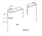
- Figure 9 illustrates an alternative embodiment of a suitable panel for a portable display system.
- Figure 1 illustrates in perspective and partially in section a hinge assembly constructed in accordance with the invention and with which a first element can be hinged to a second element, where the
first element 1 has the form of a first panel having an edge strip 1ʹ mounted thereon, and thesecond element 2 has the form of asecond panel 2 with an edge part 2ʹ mounted thereon. - It should be noted here that the inventive principles can also be applied to good effect when, for example, the
second element 2 comprises a stationary wall section, belonging to a cupboard or the like. - It is essential to the present invention, however, that at least one of the elements, for instance the
element 1, has aninternal cavity 1a located within the edge part 1ʹ, and in all events adjacent a hinge location 3. The hinge arrangement includes a hinge member 4 which couples theelement 1 to theelement 2 and functions as a hinge pin or hinge arm. - The hinge part 1ʹ of the
element 1 havingcavity 1a formed therein is provided with a plurality of mutually parallel slots, normally at least two slots, although in Figure 1 only one slot, 5, has been shown for the sake of clarity, thisslot 5 being formed at right angles to an axis ofrotation 6 which extends through the centre of thecircular cavity 1a and a member serving as a pivot orhinge pin 10. The illustrated hinge member 4 has a flat configuration and is intended to be inserted through theslot 5, preferably in the manner and in the direction illustrated in Figure 2, and is intended to be secured in thecavity 1a of the edge part 1ʹ. To this end, the hinge member 4 has formed thereon a rearwardly located bearing and guide surface, referenced 4a and 4b in Figures 2 and 4, as seen in the insertion direction. Naturally, the hinge member can be inserted in a different manner, as illustrated in Figure 5. - The bearing and guide
surfaces cavity 1a, adjacent saidslot 5, i.e. on the inner surface of the edge strip 1ʹ as illustrated by reference 7 in Figure 2. - Preferably, the edge parts 1ʹ and 2ʹ of both
elements cavities corresponding slots 5, 5ʹ, in which case the hinge member 4 will comprise a separate member having two rearwardly located bearing and guide surfaces as seen in the suitable insertion direction illustrated in Figure 2. Thus, Figure 2 not only illustrates the pair of bearing and guidesurfaces surfaces - As will be seen more clearly from the enlarged view in Figures 4, 4a and 4b, the hinge member presents, in said insertion direction, an increasing thickness and/or an outward deviation from a plane located in or parallel with the insertion direction and said slot.
- In the Figure 4 embodiment the bearing and guide
surfaces slots 8, 9 located adjacent said guide surfaces 4a and 4b, these slots enabling the guide surfaces 4a and 4b to take the position illustrated in Figure 3, although said parts can also be bent in towards a plane so that they can be pressed in through theslot 5. - In the embodiment of Figure 4, the bearing surfaces, here referenced 4cʹ and 4dʹ, on the hinge member 4 have the form of undulating surfaces.
- As illustrated in Figure 4a, the thickness of the hinge member 4 is increased in order to form said rearwardly located bearing and guide
surfaces 4e and 4eʹ, which are located symmetrically with the centre plane of the hinge member. - Figure 3 illustrates how the hinge member 4, e.g. the hinge member illustrated in Figure 4, can be inserted through the
slot 5 and thereby form a pivot or hinge pin rotatable about anaxis 6. It will be understood that the circumferential extension of theslot 5 in the illustrated tubular strip 1ʹ will determine the angle "a" through which the hinge member 4 can rotate relative to said edge strip. In the Figure 3 embodiment the extremities of theslot 5 lie slightly beyond the centre or diameter line, of thecavity 1a, thereby enabling the hinge member 4 to rotate through an angle of 180°. - When the hinge arrangement is to be used to hingedly connect two panels of a portable display system, the
slot 5 and the hinge member 4 are formed to allow the first panel to be swung in relation to the other panel through an angle of at least 180°, more suitable through an angle of 360°, i.e. twice the angle "a" illustrated in Figure 3. - It will be noted that in the case of a 360° angle, half of the angle of rotation can be allotted to one panel and half to the other panel in relation to the hinge or pivot pin, although other conditions may also apply in dependence on the form of the slot or the slots.
- The hinge member 4 of the embodiments illustrated in Figure 4 and 4a has the form of two circular, or part circular,
flat discs arm 12. Figure 4b shows only the one disc part, referenced 11ʹ. - The mutually opposing bearing and guide
surfaces disc parts panel 1, through theslot 5, with the aid of a snap-action. - In the Figure 4 embodiment, the rearwardly located bearing and guide surface is formed by diverging
slots 8, 9 and the resultant tabs are folded outwardly from a plane common to the remainder of the hinge member, to an extent such as to plastically deform certain regions within thedisc parts - In the Figure 4a embodiment, the rearwardly located bearing and guide
surfaces 4e, 4eʹ have the form of a bead located on the hinge member adjacent the connectingarm 12. - As illustrated in Figure 3, the length extension of the
slot 5 is such as to extend beyond thecentre 6 of thecircular cavity 1a through a distance corresponding exactly to half the width of the connectingarm 12, such that the angle of rotation is precisely 360°. - In the embodiment illustrated in Figure 5 one edge part 1ʹ of the
panel 1 has the form of atubular member 15, the wall thickness of which increases on theside 15a facing away from thepanel 1, and the hinge member 4 is slightly resilient and adapted, inter alia, via the connectingarm 12, to take-up the tension forces occurring during rotation and contingent on the greater wall thickness. Thepanel 2 is provided with a correspondingtubular member 16, the wall section 16a of which has a corresponding increasing thickness. - In the position illustrated in Figure 5A, with two
panels slots 5, 5ʹ, one in eachpanel disc parts arm 12. The hinge member may be inserted into respective slots in a direction parallel with the centre plane of the panels. - Figure 5B illustrates a position in which one
panel 1 has been swung in relation to theother panel 2. As will be seen from this Figure, as the panel is swung further in relation to the other panel, the thickness of the tubular member is such that the distance between thedisc parts rotational centres 6 and 6ʹ thereof will increase, therewith resulting in a compressing force between thepanels arm 12 or inward pressing of the bearing surfaces. - Larger forces can be expected to occur in the connecting
arm 12 of the embodiment shown in Figure 4a and 4b than in the embodiment shown in Figure 4. - It may be particularly suitable to provide at sections 15aʹ and 16aʹ (Fig. 5b) a wall thickness which imparts to the
surface parts 15a and 16a a circular line which results in the same force action on the hinge member 4, irrespective of the prevailing position of rotation between thepanels - Figure 5c illustrates the position in which this compressing force has reached its maximum; this force can be considered to be constant during rotation of the panels until said panels are in a straight line with one another. Although it may be suitable to provide a tubular member having the cross-sectional shape illustrated in Figure 5, it is also possible to mount on a tubular member of uniform wall thickness a collar such as to provide a tube having the cross-sectional shape of Figure 5.
- Furthermore, as illustrated in Figure 6, the surface 1ʺ of the
first panel 1 facing theother panel 2, and/or vice versa, may be provided with a coating or treated in some other way so that said surface exhibits a greater co efficient of friction, thereby to prevent relative movement between the panel surfaces, such movement possibly resulting in tilting of one panel relative to the other. - In the embodiment of Figure 6 the friction-enhancing surface 1ʺ has the form of a serrated surface, with the serrations of mutually opposite edge parts 1ʹ, 2ʹ being arranged to co-act with one another so as to prevent one panel being positioned obliquely in relation to the other.
- The invention also relates to a portable display system which can advantageously utilize a multiple of hinge arrangements of the aforedescribed kind.
- With such display systems it is proposed that the
first panel 1 and thesecond panel 2 are each intended to carry part of a complete picture, image or message. In this case, the hinge arrangement will encroach on the full picture or message only to a slight extent. - It is particularly proposed that a plurality of panels are provided with edge parts which enable said hinge arrangements to co-act with mutually opposite, parallel edge surfaces, thereby to form a continuous series of panels which are coupled together by a plurality of such hinge arrangements and which can be extended into a straight line or collapsed to form a bundle with respective panels lying against adjacent panels in a zig-zag configuration.
- Figure 7 illustrates how a number of lower panels folded to form a first bundle or package can be connected to a similar number of upper panels folded to form a second bundle or package, with the aid of a
coupling arrangement 21 comprising ahole 20a in the edge part 20ʹ of the lower panel, here referenced 20, and apin 22a located in the edge part 22ʹ of the upper panel, here referenced 22, such as to enable the panels to be extended simultaneously, two-by-two from each package or bundle, only one upper and onelower panel - This coupling arrangement will naturally enable three or more panel packages to be placed one upon the other and extended as a unit.
- This is illustrated in more detail in Figure 8, which illustrates the possibility of packing two
panels packages bag 25. When wishing to assemble the panel arrangement, the panel packages 23 and 24 are removed from thebag 25 and thepackage 23 containing the lower panels, is placed on the floor or likesupport surface 26, while thepackage 24, containing the upper panels, is placed on thepackage 23 such that the pins orpegs 22a in the lower part of the upper panel package pass into theholes 20a provided in the upper part of thelower panel package 23. - The panels are then extended in "concertina fashion" by the attendant 27.
- The hinge member 4 is then inserted at selected locations, such that mutually adjacent horizontally extending panels are pivotally hinged together.
- Figure 9 is a greatly simplified illustration of a
panel 30 which comprises a planar carryingsurface 30a having at least one edge surface 30ʹ, preferably two oppositely located edge surfaces and conceivably also three or more edge surfaces, provided with a curved section to form acavity 30a. The edge surface 30ʹ, and also other edge surfaces has one ormore slots 5 formed therein, which together with the hinge member 4 constitute a hinge arrangement in accordance with the invention, as described in the aforegoing. - A sheet of
material 31 can be mounted to one side of thecarrier surface 30a and held firmly in said curved section. - It will be understood that the invention is not restricted to the aforedescribed and illustrated embodiments, and that modifications can be carried out within the scope of the following claims.
- For example, the invention is not restricted to panels of the illustrated configuration, but can also be applied with triangular, pentagonal panels etc. This affords the possibility of creating three-dimensional constructions.
Claims (17)
Priority Applications (1)
| Application Number | Priority Date | Filing Date | Title |
|---|---|---|---|
| AT87850281T ATE74995T1 (en) | 1986-09-18 | 1987-09-17 | HINGE. |
Applications Claiming Priority (2)
| Application Number | Priority Date | Filing Date | Title |
|---|---|---|---|
| SE8603935 | 1986-09-18 | ||
| SE8603935A SE459512B (en) | 1986-09-18 | 1986-09-18 | RAILWAY AND EXHIBITION SYSTEM Utilizing said Walkway |
Publications (3)
| Publication Number | Publication Date |
|---|---|
| EP0261094A2 true EP0261094A2 (en) | 1988-03-23 |
| EP0261094A3 EP0261094A3 (en) | 1988-07-06 |
| EP0261094B1 EP0261094B1 (en) | 1992-04-15 |
Family
ID=20365637
Family Applications (1)
| Application Number | Title | Priority Date | Filing Date |
|---|---|---|---|
| EP87850281A Expired - Lifetime EP0261094B1 (en) | 1986-09-18 | 1987-09-17 | A hinge arrangement |
Country Status (6)
| Country | Link |
|---|---|
| US (1) | US4825930A (en) |
| EP (1) | EP0261094B1 (en) |
| AT (1) | ATE74995T1 (en) |
| CA (1) | CA1298055C (en) |
| DE (1) | DE3778264D1 (en) |
| SE (1) | SE459512B (en) |
Cited By (7)
| Publication number | Priority date | Publication date | Assignee | Title |
|---|---|---|---|---|
| DE3813088A1 (en) * | 1988-04-19 | 1989-11-02 | Hesterberg & Soehne Gmbh & Co | DOUBLE JOINT HINGE FOR HINGING A WING DOOR TO A FIXED WALL OF A COMMERCIAL VEHICLE |
| WO1991015646A1 (en) * | 1990-03-27 | 1991-10-17 | Esman Igor I | Hinge |
| DE4016875A1 (en) * | 1990-05-25 | 1991-11-28 | Rudi Broghammer | Rotary elastic joint coupling with invisible electric conductor - which passes through connecting piece formed integrally with axes of bearings on either side of joint |
| US5410779A (en) * | 1990-03-27 | 1995-05-02 | Esman; Igor I. | Hinge |
| WO1999041467A1 (en) * | 1998-02-16 | 1999-08-19 | Anthony Stansfield | Wall panel connection |
| EP2933467A1 (en) * | 2014-04-14 | 2015-10-21 | Rolls-Royce plc | A panel connection system and a method of using the same |
| CN111577040A (en) * | 2020-05-12 | 2020-08-25 | 合肥余塝电子商务有限公司 | Hinge assembly for door and window |
Families Citing this family (13)
| Publication number | Priority date | Publication date | Assignee | Title |
|---|---|---|---|---|
| EP0428589B1 (en) * | 1988-08-08 | 1993-11-24 | UPHAM-HILL, Christopher William | Connection system |
| US5007473A (en) * | 1989-08-02 | 1991-04-16 | Nimlock Company | Portable partition system |
| US5067182A (en) * | 1990-08-03 | 1991-11-26 | Koelsch Lester M | Swimming pool cover |
| SE501771C2 (en) * | 1993-10-05 | 1995-05-08 | Christer Zarelius | Image Exposing Device |
| US5502930A (en) * | 1993-12-30 | 1996-04-02 | Stellar Holdings, Inc. | Living hinge panel connector providing stackability of levels of panels |
| US5431210A (en) * | 1994-02-10 | 1995-07-11 | Media/Graphics, Inc. | Panel retainers |
| US5537766A (en) * | 1994-02-17 | 1996-07-23 | Classic Exhibits Inc. | Trade show display panels and display panel systems and methods for interconnecting the display panel systems |
| US5743055A (en) * | 1996-06-04 | 1998-04-28 | Hon Industries Inc. | Wall panel connector system |
| US6571519B1 (en) * | 1998-06-05 | 2003-06-03 | Krueger International, Inc. | Panel partition system with centralized power and communication distribution |
| US6250039B1 (en) | 2000-02-22 | 2001-06-26 | Abex Display Systems | Channel bar assembly for modular display systems |
| US20040168776A1 (en) * | 2002-12-20 | 2004-09-02 | Gressco, Ltd. | Free-standing panel assembly |
| US20080276420A1 (en) * | 2007-05-09 | 2008-11-13 | Wet Puppy Products, Llc | Apparatus and method for connecting decorated panels |
| US11053720B1 (en) | 2020-03-19 | 2021-07-06 | Timothy Marick | Hinge and methods of mounting and using a hinge |
Citations (5)
| Publication number | Priority date | Publication date | Assignee | Title |
|---|---|---|---|---|
| US1698136A (en) * | 1926-12-06 | 1929-01-08 | M G Lawrence | Two-way hinge |
| DE2733283A1 (en) * | 1977-07-22 | 1979-02-08 | Herrmann Hans Joachim | Extruded profile for modular frame - has rounded edges with steps to seat facing panels and apertures to locate coupling plates |
| US4147198A (en) * | 1977-10-03 | 1979-04-03 | Extraversion, Inc. | Portable display system |
| EP0109466A1 (en) * | 1982-11-23 | 1984-05-30 | Marler Haley Exposystems Limited | Adjustable structure, for example, comprising interconnected panels |
| EP0117627A2 (en) * | 1983-01-31 | 1984-09-05 | Concepts International Limited | Connecting screen panels |
Family Cites Families (4)
| Publication number | Priority date | Publication date | Assignee | Title |
|---|---|---|---|---|
| GB190207217A (en) * | 1902-03-25 | 1903-03-12 | James Collins | Improvements in Hinges or Joints for Screens and the like |
| US4448231A (en) * | 1979-06-11 | 1984-05-15 | Litton Business Systems, Inc. | Panel system edge sealing means |
| US4443911A (en) * | 1982-11-24 | 1984-04-24 | Marler Haley Exposystems Limited | Device for interconnecting panels |
| GB2159573B (en) * | 1984-05-30 | 1987-09-16 | Venesta International Componen | Improvements in and relating to hinges and door stop assemblies |
-
1986
- 1986-09-18 SE SE8603935A patent/SE459512B/en not_active IP Right Cessation
-
1987
- 1987-09-17 CA CA000547178A patent/CA1298055C/en not_active Expired - Lifetime
- 1987-09-17 AT AT87850281T patent/ATE74995T1/en active
- 1987-09-17 DE DE8787850281T patent/DE3778264D1/en not_active Expired - Lifetime
- 1987-09-17 EP EP87850281A patent/EP0261094B1/en not_active Expired - Lifetime
- 1987-09-18 US US07/098,188 patent/US4825930A/en not_active Expired - Fee Related
Patent Citations (5)
| Publication number | Priority date | Publication date | Assignee | Title |
|---|---|---|---|---|
| US1698136A (en) * | 1926-12-06 | 1929-01-08 | M G Lawrence | Two-way hinge |
| DE2733283A1 (en) * | 1977-07-22 | 1979-02-08 | Herrmann Hans Joachim | Extruded profile for modular frame - has rounded edges with steps to seat facing panels and apertures to locate coupling plates |
| US4147198A (en) * | 1977-10-03 | 1979-04-03 | Extraversion, Inc. | Portable display system |
| EP0109466A1 (en) * | 1982-11-23 | 1984-05-30 | Marler Haley Exposystems Limited | Adjustable structure, for example, comprising interconnected panels |
| EP0117627A2 (en) * | 1983-01-31 | 1984-09-05 | Concepts International Limited | Connecting screen panels |
Cited By (8)
| Publication number | Priority date | Publication date | Assignee | Title |
|---|---|---|---|---|
| DE3813088A1 (en) * | 1988-04-19 | 1989-11-02 | Hesterberg & Soehne Gmbh & Co | DOUBLE JOINT HINGE FOR HINGING A WING DOOR TO A FIXED WALL OF A COMMERCIAL VEHICLE |
| WO1991015646A1 (en) * | 1990-03-27 | 1991-10-17 | Esman Igor I | Hinge |
| US5410779A (en) * | 1990-03-27 | 1995-05-02 | Esman; Igor I. | Hinge |
| DE4016875A1 (en) * | 1990-05-25 | 1991-11-28 | Rudi Broghammer | Rotary elastic joint coupling with invisible electric conductor - which passes through connecting piece formed integrally with axes of bearings on either side of joint |
| WO1999041467A1 (en) * | 1998-02-16 | 1999-08-19 | Anthony Stansfield | Wall panel connection |
| EP2933467A1 (en) * | 2014-04-14 | 2015-10-21 | Rolls-Royce plc | A panel connection system and a method of using the same |
| US9739174B2 (en) | 2014-04-14 | 2017-08-22 | Rolls-Royce Plc | Panel connection system and a method of using the same |
| CN111577040A (en) * | 2020-05-12 | 2020-08-25 | 合肥余塝电子商务有限公司 | Hinge assembly for door and window |
Also Published As
| Publication number | Publication date |
|---|---|
| US4825930A (en) | 1989-05-02 |
| EP0261094A3 (en) | 1988-07-06 |
| DE3778264D1 (en) | 1992-05-21 |
| SE8603935D0 (en) | 1986-09-18 |
| EP0261094B1 (en) | 1992-04-15 |
| SE8603935L (en) | 1988-03-19 |
| SE459512B (en) | 1989-07-10 |
| CA1298055C (en) | 1992-03-31 |
| ATE74995T1 (en) | 1992-05-15 |
Similar Documents
| Publication | Publication Date | Title |
|---|---|---|
| EP0261094A2 (en) | A hinge arrangement | |
| US5905546A (en) | Detachable visor for lap-top computer monitor | |
| US7770864B2 (en) | Reading stand | |
| EP0179732B1 (en) | Infant's amusement device | |
| US5852853A (en) | Clothesline line tightener | |
| US4438993A (en) | Display case including improved hinge connection arrangement | |
| AU767791B2 (en) | Storage device | |
| JPH096246A (en) | Four-side folding-type signboard | |
| USD384051S (en) | Sequence structure icon for a display screen of a programmed computer system | |
| US4747572A (en) | Copy and material holder | |
| EP1933676A2 (en) | Hinged window screen | |
| US5398376A (en) | Flexible hinge for display frames and stands | |
| GB2101202A (en) | Hinges, and panel assemblies incorporating such hinges | |
| WO1995013004A1 (en) | Poster clamp | |
| US6178604B1 (en) | Clothesline line tightener | |
| JP3884013B2 (en) | blind | |
| EP0383427A2 (en) | Display panel assembly | |
| GB2323075A (en) | A receptacle | |
| JP2700630B2 (en) | Inclined bail for instruments having a substantially flat back | |
| JPH01247682A (en) | Coupling device for folding door | |
| JP2000287732A (en) | Fan | |
| CN220298163U (en) | Folding file | |
| CN114220346B (en) | Support assembly and display device | |
| JPH0752916Y2 (en) | Folding structure hinge and magazine rack using the hinge | |
| JP3805584B2 (en) | Bag handle |
Legal Events
| Date | Code | Title | Description |
|---|---|---|---|
| PUAI | Public reference made under article 153(3) epc to a published international application that has entered the european phase |
Free format text: ORIGINAL CODE: 0009012 |
|
| AK | Designated contracting states |
Kind code of ref document: A2 Designated state(s): AT BE CH DE ES FR GB GR IT LI LU NL SE |
|
| PUAL | Search report despatched |
Free format text: ORIGINAL CODE: 0009013 |
|
| AK | Designated contracting states |
Kind code of ref document: A3 Designated state(s): AT BE CH DE ES FR GB GR IT LI LU NL SE |
|
| 17P | Request for examination filed |
Effective date: 19881112 |
|
| 17Q | First examination report despatched |
Effective date: 19900702 |
|
| GRAA | (expected) grant |
Free format text: ORIGINAL CODE: 0009210 |
|
| AK | Designated contracting states |
Kind code of ref document: B1 Designated state(s): AT BE CH DE ES FR GB GR IT LI LU NL SE |
|
| PG25 | Lapsed in a contracting state [announced via postgrant information from national office to epo] |
Ref country code: IT Free format text: LAPSE BECAUSE OF FAILURE TO SUBMIT A TRANSLATION OF THE DESCRIPTION OR TO PAY THE FEE WITHIN THE PRE;WARNING: LAPSES OF ITALIAN PATENTS WITH EFFECTIVE DATE BEFORE 2007 MAY HAVE OCCURRED AT ANY TIME BEFORE 2007. THE CORRECT EFFECTIVE DATE MAY BE DIFFERENT FROM THE ONE RECORDED.SCRIBED TIME-LIMIT Effective date: 19920415 Ref country code: CH Effective date: 19920415 Ref country code: NL Effective date: 19920415 Ref country code: AT Effective date: 19920415 Ref country code: SE Effective date: 19920415 Ref country code: FR Effective date: 19920415 Ref country code: BE Effective date: 19920415 Ref country code: GR Free format text: LAPSE BECAUSE OF FAILURE TO SUBMIT A TRANSLATION OF THE DESCRIPTION OR TO PAY THE FEE WITHIN THE PRESCRIBED TIME-LIMIT Effective date: 19920415 Ref country code: LI Effective date: 19920415 |
|
| REF | Corresponds to: |
Ref document number: 74995 Country of ref document: AT Date of ref document: 19920515 Kind code of ref document: T |
|
| REF | Corresponds to: |
Ref document number: 3778264 Country of ref document: DE Date of ref document: 19920521 |
|
| PG25 | Lapsed in a contracting state [announced via postgrant information from national office to epo] |
Ref country code: ES Free format text: LAPSE BECAUSE OF FAILURE TO SUBMIT A TRANSLATION OF THE DESCRIPTION OR TO PAY THE FEE WITHIN THE PRESCRIBED TIME-LIMIT Effective date: 19920726 |
|
| REG | Reference to a national code |
Ref country code: CH Ref legal event code: PL |
|
| EN | Fr: translation not filed | ||
| NLV1 | Nl: lapsed or annulled due to failure to fulfill the requirements of art. 29p and 29m of the patents act | ||
| PG25 | Lapsed in a contracting state [announced via postgrant information from national office to epo] |
Ref country code: GB Effective date: 19920917 |
|
| PG25 | Lapsed in a contracting state [announced via postgrant information from national office to epo] |
Ref country code: LU Free format text: LAPSE BECAUSE OF NON-PAYMENT OF DUE FEES Effective date: 19920930 |
|
| PLBE | No opposition filed within time limit |
Free format text: ORIGINAL CODE: 0009261 |
|
| STAA | Information on the status of an ep patent application or granted ep patent |
Free format text: STATUS: NO OPPOSITION FILED WITHIN TIME LIMIT |
|
| 26N | No opposition filed | ||
| GBPC | Gb: european patent ceased through non-payment of renewal fee |
Effective date: 19920917 |
|
| PGFP | Annual fee paid to national office [announced via postgrant information from national office to epo] |
Ref country code: DE Payment date: 19991126 Year of fee payment: 13 |
|
| PG25 | Lapsed in a contracting state [announced via postgrant information from national office to epo] |
Ref country code: DE Free format text: LAPSE BECAUSE OF NON-PAYMENT OF DUE FEES Effective date: 20010601 |