EP0260908A2 - Thermal ignition combustion system - Google Patents
Thermal ignition combustion system Download PDFInfo
- Publication number
- EP0260908A2 EP0260908A2 EP87308094A EP87308094A EP0260908A2 EP 0260908 A2 EP0260908 A2 EP 0260908A2 EP 87308094 A EP87308094 A EP 87308094A EP 87308094 A EP87308094 A EP 87308094A EP 0260908 A2 EP0260908 A2 EP 0260908A2
- Authority
- EP
- European Patent Office
- Prior art keywords
- walls
- ignition
- chamber
- combustion system
- thermal
- Prior art date
- Legal status (The legal status is an assumption and is not a legal conclusion. Google has not performed a legal analysis and makes no representation as to the accuracy of the status listed.)
- Withdrawn
Links
Images

Classifications
-
- F—MECHANICAL ENGINEERING; LIGHTING; HEATING; WEAPONS; BLASTING
- F02—COMBUSTION ENGINES; HOT-GAS OR COMBUSTION-PRODUCT ENGINE PLANTS
- F02B—INTERNAL-COMBUSTION PISTON ENGINES; COMBUSTION ENGINES IN GENERAL
- F02B9/00—Engines characterised by other types of ignition
- F02B9/02—Engines characterised by other types of ignition with compression ignition
- F02B9/04—Methods of operating
-
- F—MECHANICAL ENGINEERING; LIGHTING; HEATING; WEAPONS; BLASTING
- F02—COMBUSTION ENGINES; HOT-GAS OR COMBUSTION-PRODUCT ENGINE PLANTS
- F02B—INTERNAL-COMBUSTION PISTON ENGINES; COMBUSTION ENGINES IN GENERAL
- F02B19/00—Engines characterised by precombustion chambers
- F02B19/14—Engines characterised by precombustion chambers with compression ignition
-
- F—MECHANICAL ENGINEERING; LIGHTING; HEATING; WEAPONS; BLASTING
- F02—COMBUSTION ENGINES; HOT-GAS OR COMBUSTION-PRODUCT ENGINE PLANTS
- F02B—INTERNAL-COMBUSTION PISTON ENGINES; COMBUSTION ENGINES IN GENERAL
- F02B19/00—Engines characterised by precombustion chambers
- F02B19/16—Chamber shapes or constructions not specific to sub-groups F02B19/02 - F02B19/10
- F02B19/165—The shape or construction of the pre-combustion chambers is specially adapted to be formed, at least in part, of ceramic material
-
- F—MECHANICAL ENGINEERING; LIGHTING; HEATING; WEAPONS; BLASTING
- F02—COMBUSTION ENGINES; HOT-GAS OR COMBUSTION-PRODUCT ENGINE PLANTS
- F02F—CYLINDERS, PISTONS OR CASINGS, FOR COMBUSTION ENGINES; ARRANGEMENTS OF SEALINGS IN COMBUSTION ENGINES
- F02F7/00—Casings, e.g. crankcases or frames
- F02F7/0085—Materials for constructing engines or their parts
- F02F7/0087—Ceramic materials
-
- F—MECHANICAL ENGINEERING; LIGHTING; HEATING; WEAPONS; BLASTING
- F02—COMBUSTION ENGINES; HOT-GAS OR COMBUSTION-PRODUCT ENGINE PLANTS
- F02P—IGNITION, OTHER THAN COMPRESSION IGNITION, FOR INTERNAL-COMBUSTION ENGINES; TESTING OF IGNITION TIMING IN COMPRESSION-IGNITION ENGINES
- F02P21/00—Direct use of flames or burners for ignition
-
- F—MECHANICAL ENGINEERING; LIGHTING; HEATING; WEAPONS; BLASTING
- F02—COMBUSTION ENGINES; HOT-GAS OR COMBUSTION-PRODUCT ENGINE PLANTS
- F02B—INTERNAL-COMBUSTION PISTON ENGINES; COMBUSTION ENGINES IN GENERAL
- F02B19/00—Engines characterised by precombustion chambers
- F02B2019/006—Engines characterised by precombustion chambers with thermal insulation
-
- F—MECHANICAL ENGINEERING; LIGHTING; HEATING; WEAPONS; BLASTING
- F05—INDEXING SCHEMES RELATING TO ENGINES OR PUMPS IN VARIOUS SUBCLASSES OF CLASSES F01-F04
- F05C—INDEXING SCHEME RELATING TO MATERIALS, MATERIAL PROPERTIES OR MATERIAL CHARACTERISTICS FOR MACHINES, ENGINES OR PUMPS OTHER THAN NON-POSITIVE-DISPLACEMENT MACHINES OR ENGINES
- F05C2203/00—Non-metallic inorganic materials
- F05C2203/08—Ceramics; Oxides
- F05C2203/0865—Oxide ceramics
- F05C2203/0895—Zirconium oxide
-
- F—MECHANICAL ENGINEERING; LIGHTING; HEATING; WEAPONS; BLASTING
- F05—INDEXING SCHEMES RELATING TO ENGINES OR PUMPS IN VARIOUS SUBCLASSES OF CLASSES F01-F04
- F05C—INDEXING SCHEME RELATING TO MATERIALS, MATERIAL PROPERTIES OR MATERIAL CHARACTERISTICS FOR MACHINES, ENGINES OR PUMPS OTHER THAN NON-POSITIVE-DISPLACEMENT MACHINES OR ENGINES
- F05C2251/00—Material properties
- F05C2251/04—Thermal properties
- F05C2251/048—Heat transfer
-
- Y—GENERAL TAGGING OF NEW TECHNOLOGICAL DEVELOPMENTS; GENERAL TAGGING OF CROSS-SECTIONAL TECHNOLOGIES SPANNING OVER SEVERAL SECTIONS OF THE IPC; TECHNICAL SUBJECTS COVERED BY FORMER USPC CROSS-REFERENCE ART COLLECTIONS [XRACs] AND DIGESTS
- Y02—TECHNOLOGIES OR APPLICATIONS FOR MITIGATION OR ADAPTATION AGAINST CLIMATE CHANGE
- Y02T—CLIMATE CHANGE MITIGATION TECHNOLOGIES RELATED TO TRANSPORTATION
- Y02T10/00—Road transport of goods or passengers
- Y02T10/10—Internal combustion engine [ICE] based vehicles
- Y02T10/12—Improving ICE efficiencies
Definitions
- This invention relates to an ignition system, and more particularly to a thermally ignited combustion system adaptable to an internal combustion engine capable of operating on a wide variety of fuels including coal, natural gas, diesel and other synthetic fuels.
- One aspect of this invention involves ignition of an air-fuel mixture through rapid heat transfer at a high temperature to the air-fuel mixture from a specially designed heat storage unit.
- insulation of various sections of the engine or use of materials having low thermal conductivity have been suggested and tried in order to enhance the performance and efficiency of the spark-ignited or diesel engine.
- a variety of such applications are disclosed in the following U.S. Patents: 4,300,497 Webber 4,511,612 Wegher 3,110,292 Dobrosavljevic 3,140,697 Péras 4,522,171 Dworak, et al.
- This invention provides a novel system for operating power systems such as the internal combustion engine and utilizes a thermal ignition process which is not dependant on the production of threshold temperatures obtained through high compression of gases to ignite the air-fuel mixture.
- the present invention utilizes pre-chamber or ignition chamber walls designed to store rather than dissipate thermal energy. The heat energy produced during combustion is stored in the specially designed walls of the ignition chamber and is then transferred directly to the next cycle air-fuel mixture causing spontaneous combustion. The result is the production of a high temperature thermal environment which promotes a higher fuel energy heat release rate than in conventional engines. This in turn results in more complete burning of the air-fuel mixture taking place in a shorter crank angle duration and producing a higher thermal and mechanical efficiency.
- One embodiment of the present invention includes a thermal ignition combustion system adapted for use with an internal combustion engine, the engine having a main combustion chamber.
- the thermal ignition combustion system comprises means for providing walls defining an ignition chamber, the walls being made of a material having a thermal conductivity greater than 20 W/m°C and a specific heat greater than 480 J/kg°C with the ignition chamber being in constant communication with the main combustion chamber, means for maintaining the temperature of the walls above a threshold temperature capable of causing ignition of a fuel, and means for conducting fuel to the ignition chamber.
- FIG. 1 there is shown a thermal ignition combustion system integrally connected to a modified single cylinder engine in accordance with one embodiment of the present invention.
- the engine adapted for this embodiment is the known 1Y73 Caterpillar having a 130.2 mm (5.125 inch) bore, 165.1 mm (6.5 inch) stroke, 2.2 liter (134.1 cubic inch) displacement and a compression ratio of 16.5 to 1.
- the unmodified engine is capable of operating in the range of 800 rpm to 1800 rpm and has a pre-chamber combustion chamber.
- the 1Y73 was adapted, as described herein, to operate on coal powder. More specifically, the fuel to be used in this embodiment is micronized Otisca coal commercially available from OTISCA Industries, Ltd. of Syracuse, New York. The coal used was bituminus coal wherein 95.7% by weight had a particle size less than 20 microns (average size approximately 5 microns), 0.8% ash content, 33,885 kJ/kg colorific value, and 0.9% sulfur content.
- the single cylinder engine 10 includes an engine block 11, cylinder walls defined by a cylinder liner 12, a piston 13 with step gap piston rings 14 and a piston rod 15, an intake port 16 with intake poppet valve 17, an exhaust port with an exhaust poppet valve 17A, a cylinder head 18 and a pre-chamber combustion chamber or ignition chamber 19.
- a main combustion chamber 22 of the unmodified engine is defined by the piston crown 20 of piston 13, cylinder head 18, cylinder liner 12 and the faces 21 of the poppet valves.
- the configuration of the exhaust port 16A and poppet valve 17A is identical to that of the intake port 16 and poppet valve 17 except for a zirconia lining within the exhaust port as will be explained herein.
- the zirconia lining 59 is not present in the commercial 1Y73 Caterpillar engine.
- the micronized coal is fumigated in the intake manifold 35 through coal delivery nozzle 30 which was added to the engine. (FIG. 3)
- the delivery nozzle is positioned to deliver the coal powder at the stricture 37 of a venturi nozzle 31, also added to the engine and located within the intake manifold 35 which leads to intake port 16.
- Arrows 32 indicate the direction of air flow within the intake manifold.
- Air passage 33 provides air to mix upstream with the incoming coal powder (shown by arrow 34) aiding to form a suspension of coal powder in air into the venturi nozzle.
- the coal feed system was constructed from commercially available elements and is shown in FIG. 2. It includes the following commercially available elements; a volumetric feeder 40, an intromitter drive 41, a variable speed DC motor 42, a screw conveyer 43, a scale with digital readout 44, a variable speed controller 45 and a flexible driveshaft 46.
- the variable speed DC motor 42 and intromitter drive 41 which are controlled by the variable speed controller 45, drive the screw conveyer 43.
- the coal powder 27 contained in the volumetric feeder 40 is directed to the injection nozzle 30 by the screw conveyer 43.
- the particle size of the coal fuel should be no greater than 20 microns.
- the coal powder should be kept free of agglomerates as it is delivered to and fumigated into the intake manifold 35.
- coal powder often has a tendency to clump, forming agglomerates which may fail to break apart upon fumigation. This may result in miniature, uncontrolled and uneven explosions within the ignition chamber 19 and main combustion chamber 22.
- a suitable means for keeping the agglomerates to a minimum, or even eliminating the agglomerates as the coal is fumigated into the intake manifold 35, may be desired.
- One approach to improve this conditon is to insert a fluidizing means 47 between the screw conveyer 43 and the delivery nozzle 30.
- the fluidizing means should break apart the agglomerates, possibly by some type of rotary/kinetic or grinding motion.
- a fluidizing means or fluidizer 210 (FIGS. 6, 7 and 8) was constructed to promote coal powder consistency free of agglomerates.
- Coal powder is fed from the feeder 40 directly into a cylindrically shaped body 211 of the fluidizer 210 through an entrance port 212 in the end plate 213.
- the body additionally has an overflow port 222, an outlet port 223 and drive shaft port 224.
- End plate 213 has several rows of fixed, radially arranged and substantially orthogonal pins 214.
- Concentrically contained within the body 211 is a cylindrical rotor 215 which also incorporated rows of radially arranged pins 216.
- the pins 216 fixed to the rotor, extend toward end plate 213 so as to overlap pins 214, but pins 216 are radially staggered relative to the pins 214 so that rotor 215 may be rotated within the body 211 without pins 214 coming in contact with pins 216.
- a flexible shaft 46 is connected between the engine camshaft 48 and the rotor 215, with O-rings 226, or some suitable sealing means, preventing the coal powder from exiting the driveshaft port 224.
- the rotor is drum shaped having a open end toward which pins 214 extend, a bottom end 217 and cylindrical side walls 218.
- the side walls 218 have a radial port 219 for passage of the coal powder through an orifice 225 in the outlet port 223 and to the intake manifold.
- the bottom 217 has an axial port 220 for passage of the coal powder to the overflow port 222.
- the coal powder After entering the fluidizer body 211, the coal powder is set into rotating motion by the rotor 215 and pins 216 which are driven by the shaft 46.
- the relative motion of the two sets of pins, 214 and 216 generates intensive kinetic agitation of the powder improving its flowability while also repulverizing any crumbs or agglomerates which may have formed.
- the flow rate of the coal powder into the fluidizer may start to exceed the flow rate out causing a back-up or excess in the fluidizer.
- Axial port 220 allows for this excess coal to pass out of the rotor, through the overflow port 222 and to a reservoir (not shown) assuring a steady state, uninhibited flow.
- measuring the overflow mass and adjusting the other above-mentioned parameters can allow the coal powder flow rate to the intake manifold 35 to be precisely controlled.
- One concept underlying this invention is ignition of an air-fuel mixture through rapid heat transfer at a high temperature to the air-fuel mixture from a specially designed heat storage unit.
- the present invention relies entirely on high temperature heat storage and subsequent rapid heat transfer from the heat storage unit to the air-fuel mixture to achieve ignition.
- the Caterpillar 1Y73 is modified as follows. The heat storage is achieved first by insulating primary combustion surfaces of the engine and by removing the cooling liquid from the passages 36 of the cooling system so as to leave air therein thereby creating a nearly adiabatic system.
- the cylinder liner 12 is cast iron and its interior surface is coated with a 1.0 mm thickness of plasma sprayed zirconia (ZrO2) 60 for insulation.
- the zirconia has a thermal conductivity of 2 W/(m ⁇ °C).
- a suitable ceramic coating is then applied over the zirconia 60 to improve the wear of the zirconia.
- a K'Ramic coating was used.
- K'Ramic is a trademark for a ceramic coating which is performed by Kaman Sciences Corp., 4765 Northpart Drive, Colorado Springs, Colorado 80907. Specifically, the K'Ramic coating contains silica, chromia, and alumina which is densified by chromic acid treatments.
- the chrome is applied in liquid form made up of hexavalent chromium and water in a variety of ways -- spraying, painting or immersion. Capillary action pulls the chrome liquid into the open pores, thereby filling the pores with the liquid chrome.
- the coating is then fired at about 1000°F which drives off the water and converts the hexavalent chrome into Cr2O3 (chrome oxide) at the same time generating an oxide bond.
- Cr2O3 chrome oxide
- a number of impregnation cycles are needed. The number of cycles varies from 5 to 15 and the final thickness is about 0.127 mm. The process is more fully described in U.S. Patent No. 3,956,531 which is hereby incorporated by reference.
- the zirconia coating may be composed of partially or fully stabilized zirconia and may be performed commercially by APS Materials, Inc., 153 Wildbrook, Dayton, Ohio 45405. Due to the increased operating temperatures and the burning and ash characteristics of coal powder, the rings also receive a K'Ramic coating to reduce wear.
- the piston is made of aluminum and the piston crown 20 is coated with a 1.2 mm thickness of plasma sprayed zirconia (ZrO2) 61.
- the crown 20 and zirconia coating 61 are then coating with a wear resistant coating. Since the 1000°F temperature of the K'Ramic process would melt the aluminum piston, an alternative coating called Zircon is used.
- Zircon is also a trademark and can be obtained commercially from Kaman Sciences Corp., 4765 Northpart Drive, Colorado Springs, Colorado 80907. Any of a host of other commercially available ceramic coatings will substitute for the Zircon including the previously described K'Ramic coating which will perform well in place of the Zircon sealer in each application described herein except for the aluminum piston.
- the cylinder head 18 is cast iron and the portion of it which is exposed to the main combustion chamber 22 is coated with a 1.40 mm thickness of plasma sprayed zirconia (ZrO2) 62 and also with a Zircon sealer.
- ZrO2 plasma sprayed zirconia
- the lining of the exhaust port 16A is also coated with a 1.0 mm thickness of plasma sprayed zirconia (ZrO2) and also with a Zircon sealer.
- the intake port 16 is not insulated as it is generally not an important source of heat loss and because the intake gases should be at a low temperature for better volumetric efficiency.
- the faces of both the intake and exhaust poppet valves 21 are likewise coated with a 1.0 mm thickness of plasma sprayed zirconia (ZrO2) 63 with a Zircon sealer. The combined insulation effect reduces the heat transfer out of the main combustion chamber resulting in a more adiabatic system.
- the ignition chamber walls 70 which define the ignition chamber, are composed of a material having a high specific heat, a high thermal conductivity and the ability to withstand the high temperatures associated with this invention.
- the mass and material composition of the chamber walls 70 have a heat capacity of at least 22 J/°C per liter displacement. This parameter is thus made to depend on the size of the engine since, as the engine displacement increases, the need for greater heat storage in the ignition chamber walls increases.
- the ignition chamber walls 70 which define the entire interior surface of the ignition chamber, are composed of cast iron.
- the barrier comprises a layer of a suitable insulating material such as a coating 71 of zirconia approximately 2.0 mm in thickness.
- the zirconia layer is applied to the exterior surface of the walls and surrounds greater than 85% of the walls.
- Further insulation of the ignition chamber is provided by an air pocket 72 surrounding the zirconia coating 71 of the ignition chamber walls 70, which in the present embodiment, is formed merely by removing the liquid from the cooling system passages 36.
- the thickness of the air pocket that is the radial distance between the zirconia coating 71 and the nearest point of material of the cylinder head 18, varies due to the non-uniform configuration of the cylinder head 18. However, the minimum thickness of the air pocket is approximately 2mm.
- the resulting system reduces the heat flow out of the engine by as much as 40% and has a capacity to store a large quantity of heat within the the silicon nitride walls 70.
- the temperature of the walls 70 of the ignition chamber will reach a minimum of 1000°F and typically, during average to peak loads, this temperature will be between 1400°F and 2000°F.
- the operating temperature of the ignition chamber walls may fall as low as 1000°F.
- the coal fuel will operate efficiently within the entire range of this system. In fact, the engine will run well on the coal powder at about 800°F.
- a glow plug 23 is provided within the ignition chamber. The use of the glow plug 23 is continued until the ignition chamber walls reach somewhere between the threshold ignition temperature of the coal powder (about 700°F) and about 800°F where the coal begins to burn efficiently.
- the compressed fuel and gas mixture temperatures will rise due to mechanical compression work, but then continue to rise due to the heat transfer from the walls 70 of the ignition chamber. This additional heat transfer creates a high temperature thermal environment which pushes the air-fuel mixture temperature well past the ignition temperature of the coal powder causing spontaneous combustion.
- the ignition temperature is approximately 700°F.
- the high temperature thermal environment attainable in this invention enables the burning of other fuels heretofore not considered practical due to their low efficiencies at conventional, non-adiabatic engine operating temperatures or to the complicated systems which are required to effect their combustion.
- One such fuel, natural gas, is the fuel used in the following alternative embodiment.
- FIG. 4 An embodiment of the thermal ignition combustion system for natural gas is illustrated in FIG. 4.
- the above-mentioned 1Y73 Caterpillar engine is again used to construct the embodiment.
- This embodiment is nearly identical to the previous embodiment, having a main combustion chamber 122, an ignition chamber 119, ignition chamber walls 170, a zirconia coating 171 surrounding the walls 170 and an air pocket 172.
- the variations involve the fuel used and the manner and timing of the fuel introduction.
- the ignition chamber 119 is defined by the ignition chamber walls 170.
- a suitable means for injecting the natural gas into the ignition chamber is provided and designated at 150.
- a standard, commerically available diesel injector may be used and easily adapted to inject natural gas at a pressure of between 3000 and 5000 psi.
- the fuel is admitted to the ignition chamber 119 through a fuel injector admission line 124.
- Injection of high pressure natural gas into the ignition chamber is achieved by actuating the opening of the injector nozzle 125 which is connected to the high pressure natural gas source 126.
- the source 126 may be either stored under pressure or compressed during operation.
- the timing of the opening and closing of the injector nozzle 125 is controlled by the hydraulic control line 127 which is supplied from a pump 128 actuated by the engine cam shaft through gearing 129, 130, 131 and 132.
- An increase in hydraulic pressure through line 127 into reservoir 140 forces piston 141 in the direction of and against biasing spring 142 which pulls up injection nozzle valve 143 allowing fuel to flow through passage 144 and to enter ignition chamber 119.
- High pressure fuel (natural gas) is delivered through a control valve 133 and through emergency shut-off valve 134.
- the high pressure natural gas is injected in a diverse spray into the combustion chamber 119 to create even and rapid mixing of the fuel with the compressing air.
- the injection occurs during the crank angle duration of approximately 10° before top dead center to 10° after top dead center.
- a glow plug 123 is provided in the ignition chamber.
- the natural gas used is approximately 90% methane and has a threshold combustion temperature of approximately 1350°F.
- the temperature of the walls 170 of the ignition chamber will be between 1400°F and 2000°F. As in the first embodiment, the result is a very efficient and complete burning of the natural gas with lower emission characteristics.
- Alternative embodiments may be produced by varying certain parameters. For example, varying the relative thicknesses of the zirconia layer 71 and of the air pocket 72 surrounding the ignition chamber walls 70 may be performed to tune the thermal ignition combustion system to operate at or within a certain desired temperature range. Thus, if the cylinder head configuration will permit up to approximately a 12 mm thickness in the air pocket 72, then no zirconia layer 71 may be required to achieve an ignition chamber wall operating temperature for coal of 1200°F or above. Conversely, where only a small air pocket is possible, a 3 mm thickness of zirconia coating 71 may be sufficient to achieve the desired ignition chamber wall operating temperature. This flexibility will also permit the engine's cooling system to be operated in its intended manner if desired. Thus, the coolant may be left in and the zirconia and/or an air pocket having an adequate thickness may be provided to achieve the same results.
- the system may also likewise be tuned to burn a variety of other fuels.
- diesel fuel which has an ignition temperature of about 500°F, may be burned more efficiently with lower emission characteristics.
- the operating temperatures of this system also will permit burning of synthetic diesel and gasoline fuels, coal derived liquid fuels, methanol or ethanol.
- the only other modification which is needed to construct a thermal ignition combustion system capable of burning another liquid or solid fuel is to design the injector means to operate with the particular fuel to be used. This task is with the knowledge of persons skilled in this art.
- Another variation which may improve the performance of the coal burning embodiment is to design the fluidizing means, or some other means designed to operate in conjunction with the fluidizer, to feed the coal powder to the intake manifold only during the period in which the intake valve is open. This will allow the coal powder fuel to be metered into the intake air at a predetermined timing during the engine operating cycle, thus improving the efficiency of the engine.
- Another variation is to feed the coal powder in a timed fashion directly into the ignition chamber.
- the material composing the walls of ignition chamber may be any of various materials which meet the requirements cited previously of high thermal conductivity, high specific heat and mass (high heat capacity) and the ability to withstand the high temperatures associated with this invention.
Abstract
Description
- This is a continuation-in-part of the prior application Serial No. 831,639, filed February 21, 1986 of Roy Kamo.
- This invention was made with Federally Funded Research Government support under Contract No. DE-AC21-84MC21099 awarded by The Department of Energy. The government has certain rights in this invention.
- This invention relates to an ignition system, and more particularly to a thermally ignited combustion system adaptable to an internal combustion engine capable of operating on a wide variety of fuels including coal, natural gas, diesel and other synthetic fuels.
- The idea of an engine operating on solid fuel, such as a coal fueled diesel engine, was examined as far back as 1900 by Rudolph Diesel. The handling of solid fuels and problems of ash deposition, however, discouraged Diesel from further pursuit of the idea. Between the early 1900's and the end of World War II, thousands of hours of intense research and development were spent trying to develop a practical solid fuel-burning engine. Several of such systems were produced such as one capable of burning coal-water slurry fuels as disclosed in United States Patent No. 4,558,664 issued to Robben or one capable of burning solvent refined coal as disclosed in United States Patent No. 3,965,870 issued to Clark. None of the systems developed however have yet satisfactorily solved the inherent problems associated with solid fuel burning such as fuel handling, ash deposition, high particulate content in emissions, low thermal efficiency, high wear and higher costs associated with the production of special fuels.
- Much technological research has also been spent in the development of the natural gas engine. The earliest gas engines were carburetted and spark ignited. Then the short lived "dual fuel engine" was developed whereby a lean mixture of natural gas was ignited by a diesel pilot. However, the expensive diesel pilot injection and the need for carrying two different fuels were soon replaced by a spark plug. Today, most of the natural gas engines are still carburetted and spark ignited with low inherent cycle efficiency and a short-lived spark plug. Only recently, high pressure gas injection into a high compression ratio engine has come under investigation. Such engines are either spark-ignited or diesel pilot-ignited during the high pressure gas injection period.
- One aspect of this invention involves ignition of an air-fuel mixture through rapid heat transfer at a high temperature to the air-fuel mixture from a specially designed heat storage unit. Heretofore, insulation of various sections of the engine or use of materials having low thermal conductivity have been suggested and tried in order to enhance the performance and efficiency of the spark-ignited or diesel engine. A variety of such applications are disclosed in the following U.S. Patents:
4,300,497 Webber
4,511,612 Hüther
3,110,292 Dobrosavljevic
3,140,697 Péras
4,522,171 Dworak, et al.
2,739,578 Stump
3,259,116 Bricout
1,798,260 Heltr
4,558,664 Robben
4,485,778 Oliver
Although increased performance in some of the important engine output parameters was realized, data in others was still unsatisfactory, such as a high particle content (soot) due to inefficient or incomplete fuel burning and the need for high compression ratios. Likewise, innovations in either solid fuel-burning engines or natural gas engines have still not produced a fuel burning system which meets the desired goals such as high thermal efficiency and low pollution content. - This invention provides a novel system for operating power systems such as the internal combustion engine and utilizes a thermal ignition process which is not dependant on the production of threshold temperatures obtained through high compression of gases to ignite the air-fuel mixture. The present invention utilizes pre-chamber or ignition chamber walls designed to store rather than dissipate thermal energy. The heat energy produced during combustion is stored in the specially designed walls of the ignition chamber and is then transferred directly to the next cycle air-fuel mixture causing spontaneous combustion. The result is the production of a high temperature thermal environment which promotes a higher fuel energy heat release rate than in conventional engines. This in turn results in more complete burning of the air-fuel mixture taking place in a shorter crank angle duration and producing a higher thermal and mechanical efficiency.
- One embodiment of the present invention includes a thermal ignition combustion system adapted for use with an internal combustion engine, the engine having a main combustion chamber. The thermal ignition combustion system comprises means for providing walls defining an ignition chamber, the walls being made of a material having a thermal conductivity greater than 20 W/m°C and a specific heat greater than 480 J/kg°C with the ignition chamber being in constant communication with the main combustion chamber, means for maintaining the temperature of the walls above a threshold temperature capable of causing ignition of a fuel, and means for conducting fuel to the ignition chamber.
- It is an object of the present invention to provide an improved ignition system for internal combustion engines.
- It is another object of the present invention to provide a fuel burning system which increases the thermal efficiency of the engine cycle.
- It is another object of the present invention to provide a fuel burning system which will operate not only on gasoline, but also on fuels such as coal, coal slurry, natural gas or diesel.
- Related objects and advantages of the present invention will become apparent from the following disclosure.
-
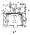
- FIG. 1 is a side elevational view, partly in cross-section, of the thermal ignition system adapted to a single cylinder engine to burn coal in accordance with one embodiment of the present invention. A portion of Fig. 1 is broken out to show the exhaust port.
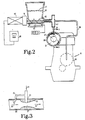
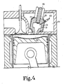
- FIG. 2 is a diagrammatic view, partially in cross-section, of the coal delivery system.
- FIG. 3 is a side cross-sectional view of the coal delivery nozzle taken along
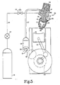
section lines 3--3 of FIG. 2. - FIG. 4 is a side elevational view, partly in section, of the thermal ignition system adapted to a single cylinder engine to burn natural gas in accordance with another embodiment of the present invention.
- FIG. 5 is a diagrammatic view of the natural gas delivery system.
- FIG. 6 is a side view, partially in cross-section, of the fluidizer, showing only those pins in the plane of the cross-section.
- FIG. 7 is a cross-sectional view of the fluidizer along the
lines 7--7 of FIG. 6, and showing only those pins connected to the rotor. - FIG. 8 is a top plan view of the fluidizer.
- For the purposes of promoting an understanding of the principles of the invention, reference will now be made to the embodiment illustrated in the drawings and specific language will be used to describe the same. It will nevertheless be understood that no limitation of the scope of the invention is thereby intended, such alterations and further modifications in the illustrated device, and such further applications of the principles of the invention as illustrated therein being contemplated as would normally occur to one skilled in the art to which the invention relates.
- Referring now to FIG. 1, there is shown a thermal ignition combustion system integrally connected to a modified single cylinder engine in accordance with one embodiment of the present invention. The engine adapted for this embodiment is the known 1Y73 Caterpillar having a 130.2 mm (5.125 inch) bore, 165.1 mm (6.5 inch) stroke, 2.2 liter (134.1 cubic inch) displacement and a compression ratio of 16.5 to 1. The unmodified engine is capable of operating in the range of 800 rpm to 1800 rpm and has a pre-chamber combustion chamber. The 1Y73 was adapted, as described herein, to operate on coal powder. More specifically, the fuel to be used in this embodiment is micronized Otisca coal commercially available from OTISCA Industries, Ltd. of Syracuse, New York. The coal used was bituminus coal wherein 95.7% by weight had a particle size less than 20 microns (average size approximately 5 microns), 0.8% ash content, 33,885 kJ/kg colorific value, and 0.9% sulfur content.
- As shown in FIG. 1, the
single cylinder engine 10 includes anengine block 11, cylinder walls defined by acylinder liner 12, apiston 13 with step gap piston rings 14 and apiston rod 15, anintake port 16 withintake poppet valve 17, an exhaust port with an exhaust poppet valve 17A, acylinder head 18 and a pre-chamber combustion chamber orignition chamber 19. Amain combustion chamber 22 of the unmodified engine is defined by thepiston crown 20 ofpiston 13,cylinder head 18,cylinder liner 12 and thefaces 21 of the poppet valves. The configuration of the exhaust port 16A and poppet valve 17A is identical to that of theintake port 16 andpoppet valve 17 except for a zirconia lining within the exhaust port as will be explained herein. Thezirconia lining 59 is not present in the commercial 1Y73 Caterpillar engine. The micronized coal is fumigated in theintake manifold 35 throughcoal delivery nozzle 30 which was added to the engine. (FIG. 3) The delivery nozzle is positioned to deliver the coal powder at thestricture 37 of aventuri nozzle 31, also added to the engine and located within theintake manifold 35 which leads tointake port 16.Arrows 32 indicate the direction of air flow within the intake manifold.Air passage 33 provides air to mix upstream with the incoming coal powder (shown by arrow 34) aiding to form a suspension of coal powder in air into the venturi nozzle. - The coal feed system, adapted for this embodiment, was constructed from commercially available elements and is shown in FIG. 2. It includes the following commercially available elements; a volumetric feeder 40, an
intromitter drive 41, a variablespeed DC motor 42, ascrew conveyer 43, a scale withdigital readout 44, avariable speed controller 45 and aflexible driveshaft 46. The variablespeed DC motor 42 andintromitter drive 41, which are controlled by thevariable speed controller 45, drive thescrew conveyer 43. Thecoal powder 27 contained in the volumetric feeder 40 is directed to theinjection nozzle 30 by thescrew conveyer 43. For optimal operation of the system described in this embodiment, the particle size of the coal fuel should be no greater than 20 microns. Also, the coal powder should be kept free of agglomerates as it is delivered to and fumigated into theintake manifold 35. When the humidity increases, coal powder often has a tendency to clump, forming agglomerates which may fail to break apart upon fumigation. This may result in miniature, uncontrolled and uneven explosions within theignition chamber 19 andmain combustion chamber 22. A suitable means for keeping the agglomerates to a minimum, or even eliminating the agglomerates as the coal is fumigated into theintake manifold 35, may be desired. One approach to improve this conditon is to insert a fluidizing means 47 between thescrew conveyer 43 and thedelivery nozzle 30. The fluidizing means should break apart the agglomerates, possibly by some type of rotary/kinetic or grinding motion. - In the present embodiment, a fluidizing means or fluidizer 210 (FIGS. 6, 7 and 8) was constructed to promote coal powder consistency free of agglomerates. Coal powder is fed from the feeder 40 directly into a cylindrically shaped
body 211 of thefluidizer 210 through anentrance port 212 in theend plate 213. The body additionally has anoverflow port 222, anoutlet port 223 and driveshaft port 224.End plate 213 has several rows of fixed, radially arranged and substantiallyorthogonal pins 214. Concentrically contained within thebody 211 is acylindrical rotor 215 which also incorporated rows of radially arranged pins 216. Thepins 216, fixed to the rotor, extend towardend plate 213 so as to overlappins 214, but pins 216 are radially staggered relative to thepins 214 so thatrotor 215 may be rotated within thebody 211 withoutpins 214 coming in contact withpins 216. Aflexible shaft 46 is connected between the engine camshaft 48 and therotor 215, with O-rings 226, or some suitable sealing means, preventing the coal powder from exiting thedriveshaft port 224. The rotor is drum shaped having a open end toward which pins 214 extend, abottom end 217 andcylindrical side walls 218. Theside walls 218 have aradial port 219 for passage of the coal powder through anorifice 225 in theoutlet port 223 and to the intake manifold. The bottom 217 has anaxial port 220 for passage of the coal powder to theoverflow port 222. - After entering the
fluidizer body 211, the coal powder is set into rotating motion by therotor 215 and pins 216 which are driven by theshaft 46. The relative motion of the two sets of pins, 214 and 216, generates intensive kinetic agitation of the powder improving its flowability while also repulverizing any crumbs or agglomerates which may have formed. For a given set of values representing the screw conveyer feed rate, rotor rpm, total mass accumulated inside the rotor, size of the orifice, and static pressure difference between inside and outside the rotor, and values related to coal rheology, the flow rate of the coal powder into the fluidizer may start to exceed the flow rate out causing a back-up or excess in the fluidizer.Axial port 220 allows for this excess coal to pass out of the rotor, through theoverflow port 222 and to a reservoir (not shown) assuring a steady state, uninhibited flow. Using the scale withdigital readout 44 to provide a metered amount of coal to the fluidizer, measuring the overflow mass and adjusting the other above-mentioned parameters can allow the coal powder flow rate to theintake manifold 35 to be precisely controlled. - One concept underlying this invention is ignition of an air-fuel mixture through rapid heat transfer at a high temperature to the air-fuel mixture from a specially designed heat storage unit. Unlike prior designs which require high compression ratios to provide diesel-type ignition, or use insulation of parts of the engine to vaporize the fuel or to aid in the diesel process, the present invention relies entirely on high temperature heat storage and subsequent rapid heat transfer from the heat storage unit to the air-fuel mixture to achieve ignition. Thus, the Caterpillar 1Y73 is modified as follows. The heat storage is achieved first by insulating primary combustion surfaces of the engine and by removing the cooling liquid from the
passages 36 of the cooling system so as to leave air therein thereby creating a nearly adiabatic system. Thecylinder liner 12 is cast iron and its interior surface is coated with a 1.0 mm thickness of plasma sprayed zirconia (ZrO₂) 60 for insulation. The zirconia has a thermal conductivity of 2 W/(m·°C). A suitable ceramic coating is then applied over thezirconia 60 to improve the wear of the zirconia. In the present embodiment, a K'Ramic coating was used. K'Ramic is a trademark for a ceramic coating which is performed by Kaman Sciences Corp., 4765 Northpart Drive, Colorado Springs, Colorado 80907. Specifically, the K'Ramic coating contains silica, chromia, and alumina which is densified by chromic acid treatments. The chrome is applied in liquid form made up of hexavalent chromium and water in a variety of ways -- spraying, painting or immersion. Capillary action pulls the chrome liquid into the open pores, thereby filling the pores with the liquid chrome. The coating is then fired at about 1000°F which drives off the water and converts the hexavalent chrome into Cr₂O₃ (chrome oxide) at the same time generating an oxide bond. In order to seal off the pores with chrome oxide, a number of impregnation cycles are needed. The number of cycles varies from 5 to 15 and the final thickness is about 0.127 mm. The process is more fully described in U.S. Patent No. 3,956,531 which is hereby incorporated by reference. - The zirconia coating may be composed of partially or fully stabilized zirconia and may be performed commercially by APS Materials, Inc., 153 Wildbrook, Dayton, Ohio 45405. Due to the increased operating temperatures and the burning and ash characteristics of coal powder, the rings also receive a K'Ramic coating to reduce wear. The piston is made of aluminum and the
piston crown 20 is coated with a 1.2 mm thickness of plasma sprayed zirconia (ZrO₂) 61. Thecrown 20 andzirconia coating 61 are then coating with a wear resistant coating. Since the 1000°F temperature of the K'Ramic process would melt the aluminum piston, an alternative coating called Zircon is used. Zircon is also a trademark and can be obtained commercially from Kaman Sciences Corp., 4765 Northpart Drive, Colorado Springs, Colorado 80907. Any of a host of other commercially available ceramic coatings will substitute for the Zircon including the previously described K'Ramic coating which will perform well in place of the Zircon sealer in each application described herein except for the aluminum piston. Thecylinder head 18 is cast iron and the portion of it which is exposed to themain combustion chamber 22 is coated with a 1.40 mm thickness of plasma sprayed zirconia (ZrO₂) 62 and also with a Zircon sealer. The lining of the exhaust port 16A is also coated with a 1.0 mm thickness of plasma sprayed zirconia (ZrO₂) and also with a Zircon sealer. Theintake port 16 is not insulated as it is generally not an important source of heat loss and because the intake gases should be at a low temperature for better volumetric efficiency. The faces of both the intake andexhaust poppet valves 21 are likewise coated with a 1.0 mm thickness of plasma sprayed zirconia (ZrO₂) 63 with a Zircon sealer. The combined insulation effect reduces the heat transfer out of the main combustion chamber resulting in a more adiabatic system. - The coating of the various combustion chamber parts and related surfaces of this embodiment are summarized below for convenience.

- The balance of the heat storage effect is achieved by the design of the pre-chamber or
ignition chamber 19. Theignition chamber walls 70, which define the ignition chamber, are composed of a material having a high specific heat, a high thermal conductivity and the ability to withstand the high temperatures associated with this invention. In addition, the mass and material composition of thechamber walls 70 have a heat capacity of at least 22 J/°C per liter displacement. This parameter is thus made to depend on the size of the engine since, as the engine displacement increases, the need for greater heat storage in the ignition chamber walls increases. In the present embodiment, theignition chamber walls 70, which define the entire interior surface of the ignition chamber, are composed of cast iron. It is the belief of the inventor that silicon nitride (Si₃N₄), which has a thermal conductivity of 25 W/(m·K) at 400K and a specific heat of 710 J/(kg°C), would perform better. Heat capacity in J/°C is the product of specific heat, expressed as J/(kg°C), and mass in kg. The 1Y73 Caterpillar has a displacement of 2.2 liters. Thus, to achieve a heat capacity of 22 J/°C per liter of displacement, the mass of the silicon nitride walls must be greater than 70g. Thewalls 70 are then provided with an insulating barrier to retain the stored heat within the ignition chamber walls. The barrier comprises a layer of a suitable insulating material such as a coating 71 of zirconia approximately 2.0 mm in thickness. The zirconia layer is applied to the exterior surface of the walls and surrounds greater than 85% of the walls. Further insulation of the ignition chamber is provided by anair pocket 72 surrounding the zirconia coating 71 of theignition chamber walls 70, which in the present embodiment, is formed merely by removing the liquid from the coolingsystem passages 36. The thickness of the air pocket, that is the radial distance between the zirconia coating 71 and the nearest point of material of thecylinder head 18, varies due to the non-uniform configuration of thecylinder head 18. However, the minimum thickness of the air pocket is approximately 2mm. - The resulting system reduces the heat flow out of the engine by as much as 40% and has a capacity to store a large quantity of heat within the the
silicon nitride walls 70. Thus, during normal engine operation, due to the high heat capacity of thewalls 70 and due to the insulation effects of the ignition and main combustion chambers, the temperature of thewalls 70 of the ignition chamber will reach a minimum of 1000°F and typically, during average to peak loads, this temperature will be between 1400°F and 2000°F. When the load on the engine is low, the operating temperature of the ignition chamber walls may fall as low as 1000°F. The coal fuel will operate efficiently within the entire range of this system. In fact, the engine will run well on the coal powder at about 800°F. While the ignition chamber walls are in the higher temperature range, however, producing a much higher thermal operating environment for the ignition process, the heat release of the coal expolsion occurs during a much shorter crank angle than in a conventional engine. Additionally, the higher temperature thermal environment causes a much more complete and efficient burning of the coal fuel. To aid in starting the engine, aglow plug 23 is provided within the ignition chamber. The use of theglow plug 23 is continued until the ignition chamber walls reach somewhere between the threshold ignition temperature of the coal powder (about 700°F) and about 800°F where the coal begins to burn efficiently. - The operation of the engine of the present embodiment with the thermal ignition system, as shown in FIG. 1, occurs as follows. During the intake stroke,
poppet valve 17 opens andpiston 13, driven bypiston rod 15 and a camshaft (not shown), draws in the air-fuel mixture (as described above) through theintake port 16. During the compression stroke,poppet valve 17 closes andpiston 13 moves upward and compresses the air-fuel mixture within themain combustion chamber 22 and theignition chamber 19. In a conventional engine, there is a tendency for the initial compressed gas temperatures to rise due to the mechanical compression work, then quickly fall due to heat transfer to the water cooled walls. In a diesel engine, the air temperature will also rise upon compression, but then fall somewhat due to heat transfer before the fuel is injected. In the present embodiment, the compressed fuel and gas mixture temperatures will rise due to mechanical compression work, but then continue to rise due to the heat transfer from thewalls 70 of the ignition chamber. This additional heat transfer creates a high temperature thermal environment which pushes the air-fuel mixture temperature well past the ignition temperature of the coal powder causing spontaneous combustion. For the powdered coal used in this embodiment, the ignition temperature is approximately 700°F. - Explosion of the air-fuel mixture then forces
piston 11 downward during the power stroke. The high temperature thermal environment created in the ignition chamber causes a much higher heat release rate of the fuel during the power stroke leading to an increase in mechanical work output and engine efficiency. The higher temperature thermal environment and higher heat release rate also results in a more complete burning of fuel resulting in more efficient fuel consumption and a decrease in levels of carbon monoxide, hydrocarbons, smoke, and particulate emissions. The insulation of the main combustion chamber surfaces 60, 61, 62 and 63 prevents the majority of heat from escaping through the engine block, piston, valves or cylinder liner. Due to the high heat capacity and thermal conductivity of theignition chamber walls 70, the extreme heat created during the combustion is partially transferred to the ignition chamber walls for storage until the intake stroke of the next cycle. The remainder of the generated and unused heat is lost to the environment during the exhaust stroke as the exhaust poppet valve 17A opens and thepiston 13 moves upward forcing the exhaust gases out exhaust port 16A. - The high temperature thermal environment attainable in this invention enables the burning of other fuels heretofore not considered practical due to their low efficiencies at conventional, non-adiabatic engine operating temperatures or to the complicated systems which are required to effect their combustion. One such fuel, natural gas, is the fuel used in the following alternative embodiment.
- An embodiment of the thermal ignition combustion system for natural gas is illustrated in FIG. 4. The above-mentioned 1Y73 Caterpillar engine is again used to construct the embodiment. This embodiment is nearly identical to the previous embodiment, having a
main combustion chamber 122, anignition chamber 119,ignition chamber walls 170, azirconia coating 171 surrounding thewalls 170 and anair pocket 172. The variations involve the fuel used and the manner and timing of the fuel introduction. As shown in FIGS. 4 and 5, theignition chamber 119 is defined by theignition chamber walls 170. A suitable means for injecting the natural gas into the ignition chamber is provided and designated at 150. A standard, commerically available diesel injector may be used and easily adapted to inject natural gas at a pressure of between 3000 and 5000 psi. As shown in FIG. 5, the fuel is admitted to theignition chamber 119 through a fuelinjector admission line 124. Injection of high pressure natural gas into the ignition chamber is achieved by actuating the opening of theinjector nozzle 125 which is connected to the high pressurenatural gas source 126. Thesource 126 may be either stored under pressure or compressed during operation. The timing of the opening and closing of theinjector nozzle 125 is controlled by thehydraulic control line 127 which is supplied from apump 128 actuated by the engine cam shaft throughgearing line 127 intoreservoir 140forces piston 141 in the direction of and against biasingspring 142 which pulls upinjection nozzle valve 143 allowing fuel to flow through passage 144 and to enterignition chamber 119. High pressure fuel (natural gas) is delivered through acontrol valve 133 and through emergency shut-offvalve 134. The high pressure natural gas is injected in a diverse spray into thecombustion chamber 119 to create even and rapid mixing of the fuel with the compressing air. The injection occurs during the crank angle duration of approximately 10° before top dead center to 10° after top dead center. - Again to aid in starting a cold engine and until the
ignition chamber walls 170 reach a temperature where the natural gas is burning efficiently, aglow plug 123 is provided in the ignition chamber. The natural gas used is approximately 90% methane and has a threshold combustion temperature of approximately 1350°F. During normal engine operation, due to the high heat capacity of thewalls 170 and to the insulation effects on the ignition andmain combustion chambers walls 170 of the ignition chamber will be between 1400°F and 2000°F. As in the first embodiment, the result is a very efficient and complete burning of the natural gas with lower emission characteristics. - Alternative embodiments may be produced by varying certain parameters. For example, varying the relative thicknesses of the zirconia layer 71 and of the
air pocket 72 surrounding theignition chamber walls 70 may be performed to tune the thermal ignition combustion system to operate at or within a certain desired temperature range. Thus, if the cylinder head configuration will permit up to approximately a 12 mm thickness in theair pocket 72, then no zirconia layer 71 may be required to achieve an ignition chamber wall operating temperature for coal of 1200°F or above. Conversely, where only a small air pocket is possible, a 3 mm thickness of zirconia coating 71 may be sufficient to achieve the desired ignition chamber wall operating temperature. This flexibility will also permit the engine's cooling system to be operated in its intended manner if desired. Thus, the coolant may be left in and the zirconia and/or an air pocket having an adequate thickness may be provided to achieve the same results. - The system may also likewise be tuned to burn a variety of other fuels. For example, diesel fuel, which has an ignition temperature of about 500°F, may be burned more efficiently with lower emission characteristics. The operating temperatures of this system also will permit burning of synthetic diesel and gasoline fuels, coal derived liquid fuels, methanol or ethanol. Aside from discretionary tuning of the ignition chamber to operate within certain temperatures, the only other modification which is needed to construct a thermal ignition combustion system capable of burning another liquid or solid fuel is to design the injector means to operate with the particular fuel to be used. This task is with the knowledge of persons skilled in this art.
- Another variation which may improve the performance of the coal burning embodiment is to design the fluidizing means, or some other means designed to operate in conjunction with the fluidizer, to feed the coal powder to the intake manifold only during the period in which the intake valve is open. This will allow the coal powder fuel to be metered into the intake air at a predetermined timing during the engine operating cycle, thus improving the efficiency of the engine.
- Another variation is to feed the coal powder in a timed fashion directly into the ignition chamber.
- The material composing the walls of ignition chamber may be any of various materials which meet the requirements cited previously of high thermal conductivity, high specific heat and mass (high heat capacity) and the ability to withstand the high temperatures associated with this invention. One such material that would meet these requirements, other than silicon nitride, is another ceramic material -- silicon carbide (SiC) (which has a thermal conductivity of 87 W/(m·K) and a specific heat of 669 J/(kg·°C).
- While the invention has been illustrated and described in detail in the drawings and foregoing description, the same is to be considered as illustrative and not restrictive in character, it being understood that only the preferred embodiment has been shown and described and that all changes and modifications that come within the spirit of the invention are desired to be protected.
Claims (21)
Applications Claiming Priority (2)
| Application Number | Priority Date | Filing Date | Title |
|---|---|---|---|
| US06/907,809 US4738227A (en) | 1986-02-21 | 1986-09-16 | Thermal ignition combustion system |
| US907809 | 1997-08-08 |
Publications (2)
| Publication Number | Publication Date |
|---|---|
| EP0260908A2 true EP0260908A2 (en) | 1988-03-23 |
| EP0260908A3 EP0260908A3 (en) | 1989-03-22 |
Family
ID=25424670
Family Applications (1)
| Application Number | Title | Priority Date | Filing Date |
|---|---|---|---|
| EP87308094A Withdrawn EP0260908A3 (en) | 1986-09-16 | 1987-09-14 | Thermal ignition combustion system |
Country Status (3)
| Country | Link |
|---|---|
| US (1) | US4738227A (en) |
| EP (1) | EP0260908A3 (en) |
| JP (1) | JPS6385216A (en) |
Cited By (6)
| Publication number | Priority date | Publication date | Assignee | Title |
|---|---|---|---|---|
| EP0420642A1 (en) * | 1989-09-29 | 1991-04-03 | Isuzu Motors Limited | Alcohol engine with combustion cavity |
| FR2669378A1 (en) * | 1990-11-19 | 1992-05-22 | Peugeot | METHOD OF MAKING A PLASMA JET CATALYTIC DEPOSITION IN A COMBUSTION CHAMBER OF AN EXPLOSION ENGINE. |
| WO1994021903A1 (en) * | 1993-03-15 | 1994-09-29 | TÖRNQVIST, Bengt, G. | Ignition gap arrangement |
| AU737759B2 (en) * | 1997-05-23 | 2001-08-30 | Honda Giken Kogyo Kabushiki Kaisha | Fuel injection internal combustion engine with sub-combustion chamber |
| DE10323841B4 (en) * | 2002-05-24 | 2008-03-20 | Nöker, Mehmet | Solid fuel powered twelve-stroke engine |
| AT523742A1 (en) * | 2020-04-16 | 2021-11-15 | Avl List Gmbh | COMBUSTION ENGINE |
Families Citing this family (45)
| Publication number | Priority date | Publication date | Assignee | Title |
|---|---|---|---|---|
| JPS63154851A (en) * | 1986-12-16 | 1988-06-28 | Kawasaki Heavy Ind Ltd | Manifold for v-type engine and manufacture thereof |
| JPH07111155B2 (en) * | 1987-04-11 | 1995-11-29 | いすゞ自動車株式会社 | Adiabatic engine structure and manufacturing method thereof |
| JPS6421220U (en) * | 1987-07-29 | 1989-02-02 | ||
| JP2718071B2 (en) * | 1988-07-21 | 1998-02-25 | いすゞ自動車株式会社 | Sub-chamber insulated engine |
| JP2736659B2 (en) * | 1988-09-19 | 1998-04-02 | ヤンマーディーゼル株式会社 | Subchamber gas engine |
| DD275891A1 (en) * | 1988-10-03 | 1990-02-07 | Barkas Werke Veb | INTERNAL COMBUSTION ENGINE WITH A CATALYTICALLY COATED COMBUSTION ENGINE |
| JPH086587B2 (en) * | 1988-10-28 | 1996-01-24 | いすゞ自動車株式会社 | Auxiliary combustion chamber type adiabatic engine |
| US5067458A (en) * | 1989-03-27 | 1991-11-26 | Caterpillar Inc. | Fuel combustion system and method of operation for an otto-cycle internal combustion engine |
| CA2056236C (en) * | 1991-11-26 | 2001-08-21 | Gary D. Webster | Internal combustion engine with high temperature variable geometry pre-combustion chamber |
| US5163385A (en) * | 1992-03-12 | 1992-11-17 | The United States Of America As Represented By The United States Department Of Energy | Coal-water slurry fuel internal combustion engine and method for operating same |
| WO1993024672A1 (en) * | 1992-05-29 | 1993-12-09 | United Technologies Corporation | Ceramic thermal barrier coating for rapid thermal cycling applications |
| US5195488A (en) * | 1992-07-14 | 1993-03-23 | Rattigan Jerry D | Internal combustion engine with unique swirl |
| JPH0686503A (en) * | 1992-09-03 | 1994-03-25 | Hitachi Ltd | Motor, polygon mirror motor and disk driving motor |
| US5305726A (en) * | 1992-09-30 | 1994-04-26 | United Technologies Corporation | Ceramic composite coating material |
| US5691636A (en) * | 1993-08-25 | 1997-11-25 | Andritz Sprout-Bauer, Inc. | Probe assembly mounting for a grinding machine |
| US5664540A (en) * | 1994-12-15 | 1997-09-09 | Isuzu Motors Limited | Pre-combustion chamber-type engine |
| DE4415073A1 (en) * | 1994-04-29 | 1995-11-02 | Fev Motorentech Gmbh & Co Kg | IC engine using alcohol-based fuel with spark ignition and direct fuel injection |
| DE19542944C2 (en) * | 1995-11-17 | 1998-01-22 | Daimler Benz Ag | Internal combustion engine and method for applying a thermal barrier coating |
| US5683825A (en) | 1996-01-02 | 1997-11-04 | General Electric Company | Thermal barrier coating resistant to erosion and impact by particulate matter |
| US6060177A (en) * | 1998-02-19 | 2000-05-09 | United Technologies Corporation | Method of applying an overcoat to a thermal barrier coating and coated article |
| US6203927B1 (en) | 1999-02-05 | 2001-03-20 | Siemens Westinghouse Power Corporation | Thermal barrier coating resistant to sintering |
| US6517960B1 (en) * | 1999-04-26 | 2003-02-11 | General Electric Company | Ceramic with zircon coating |
| KR20010110266A (en) * | 2001-11-15 | 2001-12-12 | 김창선 | A engine provided adiabatic member in the combustion chamber and a engine reusing discharging energy and high pressure jet assembly |
| US6663983B1 (en) | 2002-07-26 | 2003-12-16 | General Electric Company | Thermal barrier coating with improved strength and fracture toughness |
| CA2406137C (en) * | 2002-10-02 | 2004-12-28 | Westport Research Inc. | Control method and apparatus for gaseous fuelled internal combustion engine |
| FR2846044B1 (en) * | 2002-10-18 | 2006-07-14 | Peugeot Citroen Automobiles Sa | PRECHAMBRE IGNITION DEVICE COATED WITH A REFRACTORY COATING, FOR AN INTERNAL COMBUSTION ENGINE, AND PRE-CHAMBER IGNITER |
| US20040221830A1 (en) * | 2003-05-06 | 2004-11-11 | Cummins Inc. | Cylinder head with machined intake port and process for manufacturing |
| CA2528878C (en) * | 2003-06-10 | 2010-02-16 | Ishikawajima-Harima Heavy Industries Co., Ltd. | Turbine component, gas turbine engine, production method of turbine component, surface treatment method thereof, blade component, metal component and steam turbine engine |
| US20070099015A1 (en) * | 2005-09-15 | 2007-05-03 | Lloyd Kamo | Composite sliding surfaces for sliding members |
| US7802553B2 (en) * | 2005-10-18 | 2010-09-28 | Gm Global Technology Operations, Inc. | Method to improve combustion stability in a controlled auto-ignition combustion engine |
| US20090071434A1 (en) * | 2007-09-19 | 2009-03-19 | Macmillan Shaun T | Low heat rejection high efficiency internal combustion engine |
| DE102009016461A1 (en) * | 2009-04-04 | 2010-10-07 | Man Diesel Se | Ignition arrangement for gas engine utilized e.g., as marine engine, has ignition release device comprising ignition spark-production device that is arranged in pre-chamber for igniting ignition gas jet by ignition spark |
| US20110210279A1 (en) * | 2010-02-26 | 2011-09-01 | Midwest Sealing Products, Inc. | Gas Valves for Pneumatic Devices |
| JP5949489B2 (en) * | 2012-11-19 | 2016-07-06 | 株式会社デンソー | Internal combustion engine for solid fuel |
| US9567896B2 (en) * | 2013-01-28 | 2017-02-14 | Sonex Research, Inc. | Method for modifying combustion chamber in a reciprocating piston internal combustion engine and resulting engine |
| US9416723B2 (en) * | 2013-04-08 | 2016-08-16 | Kenneth W. Cowans | Air supply concepts to improve efficiency of VCRC engines |
| JP6446973B2 (en) * | 2014-10-07 | 2019-01-09 | トヨタ自動車株式会社 | Internal combustion engine |
| US9556832B1 (en) * | 2015-09-01 | 2017-01-31 | Combustion Engine Technologies, LLC | Adiabatic fuel injection-ignition method and device |
| US10519854B2 (en) | 2015-11-20 | 2019-12-31 | Tenneco Inc. | Thermally insulated engine components and method of making using a ceramic coating |
| US10578050B2 (en) | 2015-11-20 | 2020-03-03 | Tenneco Inc. | Thermally insulated steel piston crown and method of making using a ceramic coating |
| US9441573B1 (en) | 2015-12-09 | 2016-09-13 | Combustion Engine Technologies, LLC | Two-stroke reciprocating piston injection-ignition or compression-ignition engine |
| KR20180112791A (en) | 2016-01-14 | 2018-10-12 | 노틸러스 엔지니어링 엘엘씨 | Improved system and method of compression ignition engine |
| US10927750B2 (en) * | 2016-01-14 | 2021-02-23 | Nautilus Engineering, Llc | Systems and methods of compression ignition engines |
| WO2020014636A1 (en) * | 2018-07-12 | 2020-01-16 | Radical Combustion Technologies, Llc | Systems, apparatus, and methods for increasing combustion temperature of fuel-air mixtures in internal combustion engines |
| WO2021146550A1 (en) | 2020-01-15 | 2021-07-22 | Radical Combustion Technologies, Llc | Systems, apparatus, and methods for inducing enhanced radical ignition in internal combustion engines using a radical chemicals generator |
Citations (5)
| Publication number | Priority date | Publication date | Assignee | Title |
|---|---|---|---|---|
| US4046114A (en) * | 1975-10-06 | 1977-09-06 | General Motors Corporation | Insulated, high efficiency, low heat rejection, engine cylinder head |
| US4074671A (en) * | 1974-10-31 | 1978-02-21 | Pennila Simo A O | Thin and low specific heat ceramic coating and method for increasing operating efficiency of internal combustion engines |
| EP0015730A1 (en) * | 1979-03-02 | 1980-09-17 | Nippon Telegraph and Telephone Public Corporation | A data transmission system, and a method of passing data through a data transmission system |
| DE3315611A1 (en) * | 1982-05-06 | 1983-12-01 | Jan Johan Viktor 42174 Västra Frölunda Åbom | DEVICE FOR FINISHING THE POWDER IN POWDER ENGINES AND POWDER-OPERATED TURBINE ENGINES |
| EP0097320A2 (en) * | 1982-06-18 | 1984-01-04 | Feldmühle Aktiengesellschaft | Prechamber or swirl chamber for a combustion engine |
Family Cites Families (20)
| Publication number | Priority date | Publication date | Assignee | Title |
|---|---|---|---|---|
| US1762550A (en) * | 1925-12-10 | 1930-06-10 | Louis O French | Internal-combustion engine |
| US1798260A (en) * | 1929-02-01 | 1931-03-31 | Aerol Engine Corp | Oil engine |
| US2739578A (en) * | 1950-07-20 | 1956-03-27 | Daimler Benz Ag | Precombustion diesel engine |
| US2855908A (en) * | 1954-05-25 | 1958-10-14 | Pflaum Walter | Method of combustion and internal combustion engines |
| US3140697A (en) * | 1959-12-28 | 1964-07-14 | Renault | Compression ignition engines |
| US3110292A (en) * | 1960-09-06 | 1963-11-12 | Slobodan M Dobrosavljevic | Internal combustion engine |
| US3082752A (en) * | 1961-04-04 | 1963-03-26 | Reynolds Metals Co | Lined engine members and methods of making the same or the like |
| FR1344892A (en) * | 1962-05-28 | 1963-12-06 | Applic Tech Ind Lati | Improvements to internal combustion engines with fuel injection |
| FR1436612A (en) * | 1965-02-08 | 1966-04-29 | Applic Tech | Improvements to internal combustion engines of the thermally insulated chamber type |
| US3408995A (en) * | 1967-05-22 | 1968-11-05 | Thomas A. Johnson | Combustion chamber design and material for internal combustion cylinders and engines |
| US3965870A (en) * | 1975-03-03 | 1976-06-29 | Wallace Clark | Method of operating an internal combustion engine with solvent refined coal as a fuel |
| US4284055A (en) * | 1978-10-14 | 1981-08-18 | Lucas Industries, Limited | Reciprocating piston internal combustion engine |
| US4485778A (en) * | 1980-02-27 | 1984-12-04 | Oliver Bernard M | Method and means for improving performance of diesel engines |
| US4300497A (en) * | 1980-06-30 | 1981-11-17 | Rockwell International Corporation | Prevaporizing diesel precombustion chamber |
| US4398527A (en) * | 1980-08-22 | 1983-08-16 | Chevron Research Company | Internal combustion engine having manifold and combustion surfaces coated with a foam |
| DE3123398C2 (en) * | 1981-06-12 | 1985-04-25 | MTU Motoren- und Turbinen-Union München GmbH, 8000 München | Pre-combustion chamber for diesel engines |
| DE3133209C2 (en) * | 1981-08-21 | 1985-04-25 | MTU Motoren- und Turbinen-Union München GmbH, 8000 München | Hollow composite body, in particular body of revolution and method for its production |
| JPS5958119A (en) * | 1982-09-28 | 1984-04-03 | Mitsubishi Heavy Ind Ltd | Combustion chamber for antechamber type diesel engine |
| IT1181101B (en) * | 1984-04-04 | 1987-09-23 | Medardo Reggiani | INJECTION UNIT FOR INTERNAL COMBUSTION ENGINES FUELED WITH COMBUSTIBLE GASES SUCH AS LIQUEFIED OIL GAS OR METHANE |
| US4558664A (en) * | 1984-10-19 | 1985-12-17 | The United States Of America As Represented By The United States Department Of Energy | Superheated fuel injection for combustion of liquid-solid slurries |
-
1986
- 1986-09-16 US US06/907,809 patent/US4738227A/en not_active Expired - Fee Related
-
1987
- 1987-02-21 JP JP62036919A patent/JPS6385216A/en active Pending
- 1987-09-14 EP EP87308094A patent/EP0260908A3/en not_active Withdrawn
Patent Citations (5)
| Publication number | Priority date | Publication date | Assignee | Title |
|---|---|---|---|---|
| US4074671A (en) * | 1974-10-31 | 1978-02-21 | Pennila Simo A O | Thin and low specific heat ceramic coating and method for increasing operating efficiency of internal combustion engines |
| US4046114A (en) * | 1975-10-06 | 1977-09-06 | General Motors Corporation | Insulated, high efficiency, low heat rejection, engine cylinder head |
| EP0015730A1 (en) * | 1979-03-02 | 1980-09-17 | Nippon Telegraph and Telephone Public Corporation | A data transmission system, and a method of passing data through a data transmission system |
| DE3315611A1 (en) * | 1982-05-06 | 1983-12-01 | Jan Johan Viktor 42174 Västra Frölunda Åbom | DEVICE FOR FINISHING THE POWDER IN POWDER ENGINES AND POWDER-OPERATED TURBINE ENGINES |
| EP0097320A2 (en) * | 1982-06-18 | 1984-01-04 | Feldmühle Aktiengesellschaft | Prechamber or swirl chamber for a combustion engine |
Cited By (12)
| Publication number | Priority date | Publication date | Assignee | Title |
|---|---|---|---|---|
| EP0420642A1 (en) * | 1989-09-29 | 1991-04-03 | Isuzu Motors Limited | Alcohol engine with combustion cavity |
| FR2669378A1 (en) * | 1990-11-19 | 1992-05-22 | Peugeot | METHOD OF MAKING A PLASMA JET CATALYTIC DEPOSITION IN A COMBUSTION CHAMBER OF AN EXPLOSION ENGINE. |
| EP0487372A1 (en) * | 1990-11-19 | 1992-05-27 | Automobiles Peugeot | Process for realising a catalytic layer in a combustion chamber of an internal combustion engine by means of a plasma-spray |
| WO1994021903A1 (en) * | 1993-03-15 | 1994-09-29 | TÖRNQVIST, Bengt, G. | Ignition gap arrangement |
| AU681637B2 (en) * | 1993-03-15 | 1997-09-04 | Jan Abom | Ignition gap arrangement |
| US5706768A (en) * | 1993-03-15 | 1998-01-13 | Jan Åbom | Zigzag ignition gap arrangement |
| CN1039661C (en) * | 1993-03-15 | 1998-09-02 | 本特·G·托奎斯特 | Ignition gap arrangement |
| AU737759B2 (en) * | 1997-05-23 | 2001-08-30 | Honda Giken Kogyo Kabushiki Kaisha | Fuel injection internal combustion engine with sub-combustion chamber |
| AU737759C (en) * | 1997-05-23 | 2002-03-21 | Honda Giken Kogyo Kabushiki Kaisha | Fuel injection internal combustion engine with sub-combustion chamber |
| DE10323841B4 (en) * | 2002-05-24 | 2008-03-20 | Nöker, Mehmet | Solid fuel powered twelve-stroke engine |
| AT523742A1 (en) * | 2020-04-16 | 2021-11-15 | Avl List Gmbh | COMBUSTION ENGINE |
| AT523742B1 (en) * | 2020-04-16 | 2022-03-15 | Avl List Gmbh | COMBUSTION ENGINE |
Also Published As
| Publication number | Publication date |
|---|---|
| EP0260908A3 (en) | 1989-03-22 |
| US4738227A (en) | 1988-04-19 |
| JPS6385216A (en) | 1988-04-15 |
Similar Documents
| Publication | Publication Date | Title |
|---|---|---|
| US4738227A (en) | Thermal ignition combustion system | |
| US2773490A (en) | High expansion, spark ignited, gas burning, internal combustion engines | |
| US3508530A (en) | Internal combustion engine | |
| US4108136A (en) | Internal combustion engine control system | |
| US8550042B2 (en) | Full expansion internal combustion engine | |
| US4259932A (en) | Internal combustion engine control system | |
| CA1054942A (en) | Compound spark-ignition and diesel engine | |
| CA1293415C (en) | Internal combustion engine | |
| US2615437A (en) | Method of operating internal-combustion engines | |
| CA1069402A (en) | Internal combustion engine fuel injection system | |
| JPS58500862A (en) | internal combustion engine | |
| EP0420642B1 (en) | Alcohol engine with combustion cavity | |
| US6298825B1 (en) | Method for igniting a multi-cylinder reciprocating gas engine by injecting an ignition gas | |
| US4759319A (en) | Internal combustion engine | |
| CA2352047A1 (en) | Adiabatic internal combustion engine | |
| US5163385A (en) | Coal-water slurry fuel internal combustion engine and method for operating same | |
| US8973539B2 (en) | Full expansion internal combustion engine | |
| EP0431043A1 (en) | Thermal ignition method and apparatus for internal combustion engines | |
| US5081966A (en) | Internal combustion engine with rotary valve assembly | |
| US20180363575A1 (en) | Augmented Compression Engine (ACE) | |
| JPH07509553A (en) | Method and device for controlling combustion in a four-stroke engine | |
| EP2449223B1 (en) | Internal combustion engine with separate combustion chamber and a method to achieve modified and controlled autoignition in said chamber | |
| JPH07500648A (en) | internal combustion engine | |
| US6295965B1 (en) | Engine cylinder stratifier | |
| US6263860B1 (en) | Intake stratifier apparatus |
Legal Events
| Date | Code | Title | Description |
|---|---|---|---|
| PUAI | Public reference made under article 153(3) epc to a published international application that has entered the european phase |
Free format text: ORIGINAL CODE: 0009012 |
|
| AK | Designated contracting states |
Kind code of ref document: A2 Designated state(s): AT DE FR GB IT SE |
|
| PUAL | Search report despatched |
Free format text: ORIGINAL CODE: 0009013 |
|
| AK | Designated contracting states |
Kind code of ref document: A3 Designated state(s): AT DE FR GB IT SE |
|
| 17P | Request for examination filed |
Effective date: 19890915 |
|
| 17Q | First examination report despatched |
Effective date: 19900112 |
|
| STAA | Information on the status of an ep patent application or granted ep patent |
Free format text: STATUS: THE APPLICATION IS DEEMED TO BE WITHDRAWN |
|
| 18D | Application deemed to be withdrawn |
Effective date: 19910220 |
|
| RIN1 | Information on inventor provided before grant (corrected) |
Inventor name: VALDMANIS, EDGARS Inventor name: KAMO, ROY Inventor name: WOODS, MELVIN E. Inventor name: KAKWANI, RAMESH M. |