EP0260902A2 - Procédé de fracturation hydraulique séquentielle - Google Patents
Procédé de fracturation hydraulique séquentielle Download PDFInfo
- Publication number
- EP0260902A2 EP0260902A2 EP87308083A EP87308083A EP0260902A2 EP 0260902 A2 EP0260902 A2 EP 0260902A2 EP 87308083 A EP87308083 A EP 87308083A EP 87308083 A EP87308083 A EP 87308083A EP 0260902 A2 EP0260902 A2 EP 0260902A2
- Authority
- EP
- European Patent Office
- Prior art keywords
- fracture
- hydraulic
- stress
- test block
- polymer
- Prior art date
- Legal status (The legal status is an assumption and is not a legal conclusion. Google has not performed a legal analysis and makes no representation as to the accuracy of the status listed.)
- Granted
Links
- 238000011065 in-situ storage Methods 0.000 claims abstract description 30
- 230000015572 biosynthetic process Effects 0.000 claims abstract description 26
- 238000000034 method Methods 0.000 claims abstract description 19
- 239000012530 fluid Substances 0.000 claims abstract description 15
- 229930195733 hydrocarbon Natural products 0.000 claims abstract description 15
- 239000004215 Carbon black (E152) Substances 0.000 claims abstract description 13
- 150000002430 hydrocarbons Chemical class 0.000 claims abstract description 12
- 230000008569 process Effects 0.000 claims abstract description 9
- 229920000642 polymer Polymers 0.000 claims description 31
- 238000012360 testing method Methods 0.000 claims description 26
- 239000007788 liquid Substances 0.000 claims description 7
- 239000007787 solid Substances 0.000 claims description 7
- 229920001169 thermoplastic Polymers 0.000 claims description 7
- 239000004926 polymethyl methacrylate Substances 0.000 claims description 6
- 229910001220 stainless steel Inorganic materials 0.000 claims description 3
- 239000010935 stainless steel Substances 0.000 claims description 3
- 238000002347 injection Methods 0.000 claims description 2
- 239000007924 injection Substances 0.000 claims description 2
- 229920002401 polyacrylamide Polymers 0.000 claims description 2
- 239000004416 thermosoftening plastic Substances 0.000 claims description 2
- 125000000391 vinyl group Chemical group [H]C([*])=C([H])[H] 0.000 claims description 2
- 229920002554 vinyl polymer Polymers 0.000 claims description 2
- 229920003229 poly(methyl methacrylate) Polymers 0.000 claims 2
- 238000005755 formation reaction Methods 0.000 description 19
- 238000002474 experimental method Methods 0.000 description 6
- 230000000644 propagated effect Effects 0.000 description 5
- 239000011435 rock Substances 0.000 description 5
- 229920005372 Plexiglas® Polymers 0.000 description 4
- 230000004075 alteration Effects 0.000 description 4
- 230000003993 interaction Effects 0.000 description 4
- 238000004458 analytical method Methods 0.000 description 3
- 230000001186 cumulative effect Effects 0.000 description 3
- 230000000694 effects Effects 0.000 description 3
- 125000001183 hydrocarbyl group Chemical group 0.000 description 3
- 239000000463 material Substances 0.000 description 3
- 239000000203 mixture Substances 0.000 description 3
- 238000011084 recovery Methods 0.000 description 3
- 238000011282 treatment Methods 0.000 description 3
- 238000004590 computer program Methods 0.000 description 2
- 238000009472 formulation Methods 0.000 description 2
- 230000000977 initiatory effect Effects 0.000 description 2
- 238000012986 modification Methods 0.000 description 2
- 230000004048 modification Effects 0.000 description 2
- 239000003208 petroleum Substances 0.000 description 2
- 230000000379 polymerizing effect Effects 0.000 description 2
- 239000004971 Cross linker Substances 0.000 description 1
- 241000274177 Juniperus sabina Species 0.000 description 1
- 238000003491 array Methods 0.000 description 1
- 238000006243 chemical reaction Methods 0.000 description 1
- 238000004891 communication Methods 0.000 description 1
- 238000013461 design Methods 0.000 description 1
- 238000009533 lab test Methods 0.000 description 1
- 238000004519 manufacturing process Methods 0.000 description 1
- 239000000178 monomer Substances 0.000 description 1
- 230000003287 optical effect Effects 0.000 description 1
- 230000002572 peristaltic effect Effects 0.000 description 1
- 239000004033 plastic Substances 0.000 description 1
- 229920003023 plastic Polymers 0.000 description 1
- 238000006116 polymerization reaction Methods 0.000 description 1
- 230000001902 propagating effect Effects 0.000 description 1
- 230000001681 protective effect Effects 0.000 description 1
- 230000004044 response Effects 0.000 description 1
- 235000001520 savin Nutrition 0.000 description 1
- 230000000638 stimulation Effects 0.000 description 1
- XLYOFNOQVPJJNP-UHFFFAOYSA-N water Substances O XLYOFNOQVPJJNP-UHFFFAOYSA-N 0.000 description 1
Images


Classifications
-
- E—FIXED CONSTRUCTIONS
- E21—EARTH OR ROCK DRILLING; MINING
- E21B—EARTH OR ROCK DRILLING; OBTAINING OIL, GAS, WATER, SOLUBLE OR MELTABLE MATERIALS OR A SLURRY OF MINERALS FROM WELLS
- E21B49/00—Testing the nature of borehole walls; Formation testing; Methods or apparatus for obtaining samples of soil or well fluids, specially adapted to earth drilling or wells
- E21B49/006—Measuring wall stresses in the borehole
-
- E—FIXED CONSTRUCTIONS
- E21—EARTH OR ROCK DRILLING; MINING
- E21B—EARTH OR ROCK DRILLING; OBTAINING OIL, GAS, WATER, SOLUBLE OR MELTABLE MATERIALS OR A SLURRY OF MINERALS FROM WELLS
- E21B43/00—Methods or apparatus for obtaining oil, gas, water, soluble or meltable materials or a slurry of minerals from wells
- E21B43/16—Enhanced recovery methods for obtaining hydrocarbons
- E21B43/17—Interconnecting two or more wells by fracturing or otherwise attacking the formation
-
- E—FIXED CONSTRUCTIONS
- E21—EARTH OR ROCK DRILLING; MINING
- E21B—EARTH OR ROCK DRILLING; OBTAINING OIL, GAS, WATER, SOLUBLE OR MELTABLE MATERIALS OR A SLURRY OF MINERALS FROM WELLS
- E21B43/00—Methods or apparatus for obtaining oil, gas, water, soluble or meltable materials or a slurry of minerals from wells
- E21B43/25—Methods for stimulating production
- E21B43/26—Methods for stimulating production by forming crevices or fractures
-
- E—FIXED CONSTRUCTIONS
- E21—EARTH OR ROCK DRILLING; MINING
- E21B—EARTH OR ROCK DRILLING; OBTAINING OIL, GAS, WATER, SOLUBLE OR MELTABLE MATERIALS OR A SLURRY OF MINERALS FROM WELLS
- E21B47/00—Survey of boreholes or wells
- E21B47/02—Determining slope or direction
-
- G—PHYSICS
- G09—EDUCATION; CRYPTOGRAPHY; DISPLAY; ADVERTISING; SEALS
- G09B—EDUCATIONAL OR DEMONSTRATION APPLIANCES; APPLIANCES FOR TEACHING, OR COMMUNICATING WITH, THE BLIND, DEAF OR MUTE; MODELS; PLANETARIA; GLOBES; MAPS; DIAGRAMS
- G09B23/00—Models for scientific, medical, or mathematical purposes, e.g. full-sized devices for demonstration purposes
- G09B23/40—Models for scientific, medical, or mathematical purposes, e.g. full-sized devices for demonstration purposes for geology
-
- G—PHYSICS
- G09—EDUCATION; CRYPTOGRAPHY; DISPLAY; ADVERTISING; SEALS
- G09B—EDUCATIONAL OR DEMONSTRATION APPLIANCES; APPLIANCES FOR TEACHING, OR COMMUNICATING WITH, THE BLIND, DEAF OR MUTE; MODELS; PLANETARIA; GLOBES; MAPS; DIAGRAMS
- G09B25/00—Models for purposes not provided for in G09B23/00, e.g. full-sized devices for demonstration purposes
- G09B25/02—Models for purposes not provided for in G09B23/00, e.g. full-sized devices for demonstration purposes of industrial processes; of machinery
- G09B25/025—Models for purposes not provided for in G09B23/00, e.g. full-sized devices for demonstration purposes of industrial processes; of machinery hydraulic; pneumatic
Definitions
- This invention relates to the ability to control the direction of hydraulic fracture propagation in a subsurface formation by hydraulically fracturing the formation in a sequential manner. In hydrocarbon-bearing formations, this could significantly increase well productivity and reservoir cumulative recovery, especially in naturally fractured reservoirs.
- Hydraulic fracturing is well established in the oil industry.
- the direction of fracture propagation is primarily controlled by the present orientation of the subsurface ("in-situ") stresses. These stresses are usually resolved into a maximum in-situ stress and a minimum in-situ stress. These two stresses are mutually perpendicular (usually in a horizontal plane) and are assumed to be acting uniformly on a subsurface formation at a distance greatly removed from the site of a hydraulic fracturing operation (i.e., these are "far-field” in-situ stresses).
- the direction that a hydraulic fracture will propagate from a wellbore into a subsurface formation is perpendicular to the least principal in-situ stress.
- any induced hydraulic fracture will tend to propagate parallel to the natural fractures. This results in only poor communication between the wellbore and the natural fracture system and does not provide for optimum drainage of reservoir hydrocarbons.
- This invention is directed to a method for the sequential hydraulic fracturing of a hydrocarbon-bearing formation penetrated by two closely-spaced wells.
- sequential hydraulic fracturing the direction that a hydraulic fracture will propagate is controlled by altering the local in-situ stress distribution in the vicinity of the first wellbore.
- a hydraulic fracturing operation is conducted at the first wellbore wherein a hydraulic pressure is applied to the formation sufficient to cause a hydraulic fracture to form perpendicular to the least principal in-situ stress.
- a second hydraulic fracture is initiated in the second wellbore.
- This second hydraulic fracture due to the alteration of the local in-situ stresses by the first hydraulic fracture will initiate at an angle, possibly perpendicular, to the first hydraulic fracture.
- this second hydraulic fracture then has the potential of intersecting natural fractures not contacted by the first hydraulic fracture, thereby significantly improving the potential for enhanced hydrocarbon production and cumulative recovery.
- the method is applied to the second wellbore sufficient to cause the second hydraulic fracture to intersect at least one hydrocarbon-bearing natural fracture. Thereafter, pressure is released in both the first and second hydraulic fractures and hydrocarbons are produced from the formation.
- This invention provides a process for predicting hydraulic fracturing trajectories in a natural hydrocarbon fluid bearing formation whereby utilizing uniaxial stress, a force can be generated sufficient to cause triaxial stress in a model comprising:
- hydraulic fracturing is initiated at one well in a formation containing two closely-spaced wells.
- a hydraulic fracturing technique is discussed in U.S. Patent No. 4,067,389, issued to Savins on January 10, 1978.
- Another method for initiating hydraulic fracturing is disclosed by Medlin et al. in U.S. Patent No. 4,378,845 which issued on April 5, 1983.
- the hydraulic pressure applied in order to initiate hydraulic fracturing in the formation, the hydraulic pressure applied must exceed the formation pressures in order to cause a fracture to form.
- the fracture which forms will generally run perpendicularly to the least principal stress in the formation or reservoir.
- Natural fractures also form perpendicularly to the least principal in-situ stress.
- the natural fracture "trend" is dictated by the geological stresses that were in existence at the time the natural fractures were formed.
- the orientations of these geoligical stresses often coincide with the orientations of the present-day subsurface in-situ stresses. In these cases, the result is that a hydraulically induced fracture will tend to assume an orientation that is parallel to that of the natural fracture system.
- This invention utilizes the in-situ stress changes due to hydraulic fracturing in one well to control the direction of propagation of a second hydraulic fracture in a second well located nearby the first well.
- the hydraulic pressure is maintained on the formation.
- This first hydraulic fracture forms parallel to the fractures in the natural fracture system.
- another hydraulic fracturing operation is conducted at a second well within the zone of in-situ stress alteration due to the first hydraulic fracture. Pressure is then applied via the second well sufficient to cause a second hydraulically induced fracture to form in said formation.
- This second hydraulic fracture initiates at an angle, often perpendicular, to the first hydraulic fracture and curves away from the first hydraulic fracture as it propagates.
- This second hydraulic fracture intersects at least one natural hydrocarbon fluid-bearing fracture. Thereafter, the pressures are relieved in both wells and hydrocarbon fluids are produced therefrom.
- the modelling medium selected was Halliburton's "K-Trol" polyacrylamide polymer. Different strengths and properties can be obtained by varying the amounts of monomer and cross-linker that are used in the polymer. "K-Trol” sets up by an exothermic reaction. This polymer can be fractured hydraulically and the more rigid formulations showed photoelastic stress patterns under polarized light. It was further determined that the material was linear elastic (i.e., a plot of stress versus strain is a straight line, as shown in Figure 1). The polymer showed essentially no stress hysteresis, and behaved in a manner similar to rock (e.g., crushes like rock).
- this polymer is moldable (in layers when necessary to represent geological model situations), (b) it is transparent so that what is taking place can be observed as it happens, (c) pressures necessary for stressing the model are very low (a few kPa [psi]), (d) large models can be constructed to minimize edge effects and to accommodate multi-well arrays, and (e) media over a broad range of rigidities can be readily formulated.
- a polymer block was molded in a substantially well-oiled Plexiglas mold with an oil layer floated on top of the polymerizing fluid.
- the polymer block was formed in three layers.
- the layer to be hydraulically fractured was usually about 51 mm (2 inches) thick and sandwiched between two 6.4 mm (1/4 inch) layers of a less rigid polymer composition. The reason for this was to contain the fracture within the thicker layer and prevent the fracturing fluid from escaping elsewhere in the model system.
- Each polymer layer required approximately 1 to 2 hours to set up sufficiently before another layer could be added. Additional layers were poured directly through the protective oil layer and became bonded to the underlying layer upon polymerizing. The time required for full-strength polymerization is about 24 hours.
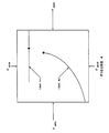
- a Plexiglas stress frame as shown in Figures 2 and 2A was used to stress the polymer block triaxially (i.e., three mutually perpendicular stresses of different magnitudes).
- This frame has internal dimensions of about 356 x 356 x 127 mm (13 x 14 x 5 inches) and is constructed of 25 mm (1 inch) thick Plexiglas of substantially good optical quality.
- the polymer test block was stressed in the following manner. First, the test block was molded so that its dimensions were less than those of the stress frame. The dimensions of the test block are dictated by the Young's modulus of the polymer formulation being stressed and the desired magnitudes of the boundary stresses. A representation of the determination of Young's modulus from a plot of stress versus strain is depicted in Figure 1.
- the stress frame is loaded uniaxially, triaxial stresses are obtained due to deformation of the polymer block and its interaction with the walls of the stress frame. As a load is applied to one set of faces of the polymer block, the block will begin to deform. At some point, a second set of faces will come into contact with the walls of the stress frame and start building up pressure against these walls. Later, after further deformation, the third set of faces will touch the remaining walls and start building up pressure there. The result is triaxial stress obtained from uniaxial loading.
- the load is applied by means of a pressurized bladded 22 as shown in Figures 2 and 2A. Both water and air are used to pressurize the bladder.
- This bladder is made of 0.2 mm (8 x 10 ⁇ 3 inch vinyl) that was cut and heat sealed into form.
- a Plexiglas plate 15 above the bladder transmits the load (usually less than 14 kPa (2 psi) to the polymer block 14.
- Oil is the principal fracturing fluid utilized. Oil was selected because it does not penetrate into the polymer block and is easily dyed with the oil-based dye "Oil Red-O".
- the fracturing fluid is injected into the polymer block via "wellbores" 12 through the top 18 of the triaxial stress frame in Figure 2.
- These "wellbores” are lengths of stainless steel hypodermic tubing that are set in place after the polymer block 14 is stressed. They are secured in position with Swage-lock fittings 16 mounted in the top of the stress frame as shown in Figure 2.
- Plastic tubing 20 connects these fittings to small laboratory peristaltic pumps (not shown) which provide the fracturing fluid pressures.
- Non-interacting hydraulic fracturing is defined to mean the process of creating a fracture and releasing the pressure in the fracture prior to the initiation of a subsequent fracture as is common practice to those skilled in the art.
- Sequential hydraulic fracturing is defined to mean the technique whereby a new hydraulic fracture is created or an existing fracture is pressurized, held at a stabilized pressure, and another hydraulic fracture is initiated in a nearby wellbore.
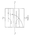
- Figure 4 illustrates the results of sequential hydraulic fracturing in the low-pressure triaxial stress frame.
- fracture #1 was initiated first. It propagated perpendicular to the least principal in-situ stress as indicated. While pressure was maintained on fracture #1, fracture #2 was initiated and propagated. Due to the alteration of the local in-situ stress field by fracture #1, fracture #2 curved away from fracture #1 in a manner similar to that shown in Figure 4.
- Sequential hydraulic fracturing was also performed in a high-pressure polyaxial test cell in synthetic rock subjected to realistic subsurface in-situ stress conditions.
- a 1.5 cubic-fot block of porous, mechanically rock-like material (“Hydrostone”) was subjected to an "overburden" stress of 16550 kPa (2400 psi) and horizontal stresses of 7585 kPa (1100 psi) in one direction and 860 kPa (1300 psi) in the perpendicular direction.
- Two 1/8 inch stainless steel tubing "wells" were placed in the block and the block was hydraulically fractured in a sequential manner.
- the first hydraulic fracture formed perpendicular to the least principal stress (i.e., perpendicular to the 7585 kPa (1100 psi) stress).
- the second, sequential hydraulic fracture propagated perpendicular to the first hydraulic fracture.
- Figure 5 shows theoretical hydraulic fractures that might form in a biaxial stress field that is influenced by a pressurized fracture. Due to symmetry of the problem, this figure represents only one quadrant of the full picture. If it is assumed that there is a 10 acre well spacing, 14824 kPa (2150 psi) in the first fracture, and that other induced hydraulic fractures will tend to have equal wings up to a maximum of 274 m (900 feet), the results shown in Figure 5 are obtained.
- the importance of the location of the wellbore for the second hydraulic fracture is related to the length of and the pressure in the first hydraulic fracture of the sequential fracturing well-pair. The greater the length of or the greater the pressure in this first fracture, the further away the effects can be felt.
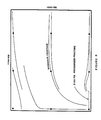
- Figure 7 illustrates conventional non-interacting hydraulic fracturing in a naturally fractured reservoir.
- the hydraulic fractures are parallel to the natural fractures.
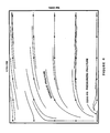
- Figure 8 depicts sequential hydraulic fracturing in a naturally fractured reservoir. This shows that, when the second fracture is initiated and propagated sequentially, it will tend to curve away from the first hydraulic fracture, out into the natural fracture system, and link it to the wellbore.
Landscapes
- Engineering & Computer Science (AREA)
- Geology (AREA)
- Life Sciences & Earth Sciences (AREA)
- Physics & Mathematics (AREA)
- Mining & Mineral Resources (AREA)
- Geochemistry & Mineralogy (AREA)
- General Life Sciences & Earth Sciences (AREA)
- Environmental & Geological Engineering (AREA)
- Fluid Mechanics (AREA)
- General Physics & Mathematics (AREA)
- Theoretical Computer Science (AREA)
- Business, Economics & Management (AREA)
- Educational Technology (AREA)
- Educational Administration (AREA)
- Mathematical Analysis (AREA)
- Algebra (AREA)
- Computational Mathematics (AREA)
- Paleontology (AREA)
- Mathematical Optimization (AREA)
- Mathematical Physics (AREA)
- Pure & Applied Mathematics (AREA)
- Geophysics (AREA)
- Investigating Strength Of Materials By Application Of Mechanical Stress (AREA)
- Diaphragms For Electromechanical Transducers (AREA)
- Blow-Moulding Or Thermoforming Of Plastics Or The Like (AREA)
- Lubrication Of Internal Combustion Engines (AREA)
Applications Claiming Priority (2)
| Application Number | Priority Date | Filing Date | Title |
|---|---|---|---|
| US907260 | 1986-09-15 | ||
| US06/907,260 US4724905A (en) | 1986-09-15 | 1986-09-15 | Sequential hydraulic fracturing |
Publications (3)
| Publication Number | Publication Date |
|---|---|
| EP0260902A2 true EP0260902A2 (fr) | 1988-03-23 |
| EP0260902A3 EP0260902A3 (en) | 1989-05-03 |
| EP0260902B1 EP0260902B1 (fr) | 1991-11-21 |
Family
ID=25423783
Family Applications (1)
| Application Number | Title | Priority Date | Filing Date |
|---|---|---|---|
| EP87308083A Expired - Lifetime EP0260902B1 (fr) | 1986-09-15 | 1987-09-14 | Procédé de fracturation hydraulique séquentielle |
Country Status (5)
| Country | Link |
|---|---|
| US (1) | US4724905A (fr) |
| EP (1) | EP0260902B1 (fr) |
| CA (1) | CA1281278C (fr) |
| DE (1) | DE3774649D1 (fr) |
| NO (1) | NO170046C (fr) |
Cited By (1)
| Publication number | Priority date | Publication date | Assignee | Title |
|---|---|---|---|---|
| CN108333050A (zh) * | 2017-12-29 | 2018-07-27 | 中国海洋石油集团有限公司 | 一种真三轴状态下煤岩二次水力压裂试验方法 |
Families Citing this family (85)
| Publication number | Priority date | Publication date | Assignee | Title |
|---|---|---|---|---|
| US4830106A (en) * | 1987-12-29 | 1989-05-16 | Mobil Oil Corporation | Simultaneous hydraulic fracturing |
| US4869322A (en) * | 1988-10-07 | 1989-09-26 | Mobil Oil Corporation | Sequential hydraulic fracturing of a subsurface formation |
| US5111881A (en) * | 1990-09-07 | 1992-05-12 | Halliburton Company | Method to control fracture orientation in underground formation |
| US5228510A (en) * | 1992-05-20 | 1993-07-20 | Mobil Oil Corporation | Method for enhancement of sequential hydraulic fracturing using control pulse fracturing |
| US5295539A (en) * | 1992-09-17 | 1994-03-22 | Mobil Oil Corporation | Two well hydrocarbon producing method using multiple fractures |
| US5261489A (en) * | 1992-09-17 | 1993-11-16 | Mobil Oil Corporation | Two well hydrocarbon producing method |
| US5285683A (en) * | 1992-10-01 | 1994-02-15 | Halliburton Company | Method and apparatus for determining orientation of a wellbore relative to formation stress fields |
| US5482116A (en) * | 1993-12-10 | 1996-01-09 | Mobil Oil Corporation | Wellbore guided hydraulic fracturing |
| US6216783B1 (en) * | 1998-11-17 | 2001-04-17 | Golder Sierra, Llc | Azimuth control of hydraulic vertical fractures in unconsolidated and weakly cemented soils and sediments |
| US6793018B2 (en) | 2001-01-09 | 2004-09-21 | Bj Services Company | Fracturing using gel with ester delayed breaking |
| DK174493B1 (da) * | 2001-05-22 | 2003-04-22 | Maersk Olie & Gas | Fremgangsmåde til styring af injektionsfrakturers udbredelsesretning i permeable formationer |
| US8273693B2 (en) * | 2001-12-12 | 2012-09-25 | Clearwater International Llc | Polymeric gel system and methods for making and using same in hydrocarbon recovery |
| US7268100B2 (en) * | 2004-11-29 | 2007-09-11 | Clearwater International, Llc | Shale inhibition additive for oil/gas down hole fluids and methods for making and using same |
| US8563481B2 (en) | 2005-02-25 | 2013-10-22 | Clearwater International Llc | Corrosion inhibitor systems for low, moderate and high temperature fluids and methods for making and using same |
| US7740072B2 (en) * | 2006-10-10 | 2010-06-22 | Halliburton Energy Services, Inc. | Methods and systems for well stimulation using multiple angled fracturing |
| US7946340B2 (en) * | 2005-12-01 | 2011-05-24 | Halliburton Energy Services, Inc. | Method and apparatus for orchestration of fracture placement from a centralized well fluid treatment center |
| US20070125544A1 (en) * | 2005-12-01 | 2007-06-07 | Halliburton Energy Services, Inc. | Method and apparatus for providing pressure for well treatment operations |
| US7711487B2 (en) * | 2006-10-10 | 2010-05-04 | Halliburton Energy Services, Inc. | Methods for maximizing second fracture length |
| US7836949B2 (en) * | 2005-12-01 | 2010-11-23 | Halliburton Energy Services, Inc. | Method and apparatus for controlling the manufacture of well treatment fluid |
| US7841394B2 (en) * | 2005-12-01 | 2010-11-30 | Halliburton Energy Services Inc. | Method and apparatus for centralized well treatment |
| US8950493B2 (en) * | 2005-12-09 | 2015-02-10 | Weatherford Technology Holding LLC | Method and system using zeta potential altering compositions as aggregating reagents for sand control |
| US8871694B2 (en) | 2005-12-09 | 2014-10-28 | Sarkis R. Kakadjian | Use of zeta potential modifiers to decrease the residual oil saturation |
| US8946130B2 (en) * | 2005-12-09 | 2015-02-03 | Clearwater International Llc | Methods for increase gas production and load recovery |
| US9334713B2 (en) | 2005-12-09 | 2016-05-10 | Ronald van Petegem | Produced sand gravel pack process |
| US8097567B2 (en) | 2006-01-09 | 2012-01-17 | Clearwater International, Llc | Well drilling fluids having clay control properties |
| US8084401B2 (en) | 2006-01-25 | 2011-12-27 | Clearwater International, Llc | Non-volatile phosphorus hydrocarbon gelling agent |
| US7921046B2 (en) * | 2006-06-19 | 2011-04-05 | Exegy Incorporated | High speed processing of financial information using FPGA devices |
| US7712535B2 (en) * | 2006-10-31 | 2010-05-11 | Clearwater International, Llc | Oxidative systems for breaking polymer viscosified fluids |
| US7848895B2 (en) * | 2007-01-16 | 2010-12-07 | The Board Of Trustees Of The Leland Stanford Junior University | Predicting changes in hydrofrac orientation in depleting oil and gas reservoirs |
| US8172952B2 (en) * | 2007-02-21 | 2012-05-08 | Clearwater International, Llc | Reduction of hydrogen sulfide in water treatment systems or other systems that collect and transmit bi-phasic fluids |
| US7992653B2 (en) | 2007-04-18 | 2011-08-09 | Clearwater International | Foamed fluid additive for underbalance drilling |
| US7565933B2 (en) * | 2007-04-18 | 2009-07-28 | Clearwater International, LLC. | Non-aqueous foam composition for gas lift injection and methods for making and using same |
| US8158562B2 (en) * | 2007-04-27 | 2012-04-17 | Clearwater International, Llc | Delayed hydrocarbon gel crosslinkers and methods for making and using same |
| US7942201B2 (en) * | 2007-05-11 | 2011-05-17 | Clearwater International, Llc | Apparatus, compositions, and methods of breaking fracturing fluids |
| US8034750B2 (en) * | 2007-05-14 | 2011-10-11 | Clearwater International Llc | Borozirconate systems in completion systems |
| US8728989B2 (en) * | 2007-06-19 | 2014-05-20 | Clearwater International | Oil based concentrated slurries and methods for making and using same |
| US8099997B2 (en) | 2007-06-22 | 2012-01-24 | Weatherford/Lamb, Inc. | Potassium formate gel designed for the prevention of water ingress and dewatering of pipelines or flowlines |
| US8065905B2 (en) | 2007-06-22 | 2011-11-29 | Clearwater International, Llc | Composition and method for pipeline conditioning and freezing point suppression |
| US7931082B2 (en) * | 2007-10-16 | 2011-04-26 | Halliburton Energy Services Inc., | Method and system for centralized well treatment |
| US7989404B2 (en) * | 2008-02-11 | 2011-08-02 | Clearwater International, Llc | Compositions and methods for gas well treatment |
| US7730951B2 (en) * | 2008-05-15 | 2010-06-08 | Halliburton Energy Services, Inc. | Methods of initiating intersecting fractures using explosive and cryogenic means |
| US8141661B2 (en) * | 2008-07-02 | 2012-03-27 | Clearwater International, Llc | Enhanced oil-based foam drilling fluid compositions and method for making and using same |
| US7956217B2 (en) | 2008-07-21 | 2011-06-07 | Clearwater International, Llc | Hydrolyzed nitrilotriacetonitrile compositions, nitrilotriacetonitrile hydrolysis formulations and methods for making and using same |
| US8287640B2 (en) * | 2008-09-29 | 2012-10-16 | Clearwater International, Llc | Stable foamed cement slurry compositions and methods for making and using same |
| US9909404B2 (en) | 2008-10-08 | 2018-03-06 | The Lubrizol Corporation | Method to consolidate solid materials during subterranean treatment operations |
| US9945220B2 (en) | 2008-10-08 | 2018-04-17 | The Lubrizol Corporation | Methods and system for creating high conductivity fractures |
| US7932214B2 (en) * | 2008-11-14 | 2011-04-26 | Clearwater International, Llc | Foamed gel systems for fracturing subterranean formations, and methods for making and using same |
| US8011431B2 (en) * | 2009-01-22 | 2011-09-06 | Clearwater International, Llc | Process and system for creating enhanced cavitation |
| US8093431B2 (en) * | 2009-02-02 | 2012-01-10 | Clearwater International Llc | Aldehyde-amine formulations and method for making and using same |
| US9328285B2 (en) * | 2009-04-02 | 2016-05-03 | Weatherford Technology Holdings, Llc | Methods using low concentrations of gas bubbles to hinder proppant settling |
| US8466094B2 (en) | 2009-05-13 | 2013-06-18 | Clearwater International, Llc | Aggregating compositions, modified particulate metal-oxides, modified formation surfaces, and methods for making and using same |
| US20100305010A1 (en) * | 2009-05-28 | 2010-12-02 | Clearwater International, Llc | High density phosphate brines and methods for making and using same |
| US20100311620A1 (en) * | 2009-06-05 | 2010-12-09 | Clearwater International, Llc | Winterizing agents for oil base polymer slurries and method for making and using same |
| US20110001083A1 (en) * | 2009-07-02 | 2011-01-06 | Clearwater International, Llc | Environmentally benign water scale inhibitor compositions and method for making and using same |
| US8796188B2 (en) | 2009-11-17 | 2014-08-05 | Baker Hughes Incorporated | Light-weight proppant from heat-treated pumice |
| US9447657B2 (en) | 2010-03-30 | 2016-09-20 | The Lubrizol Corporation | System and method for scale inhibition |
| US8835364B2 (en) | 2010-04-12 | 2014-09-16 | Clearwater International, Llc | Compositions and method for breaking hydraulic fracturing fluids |
| US8899328B2 (en) | 2010-05-20 | 2014-12-02 | Clearwater International Llc | Resin sealant for zonal isolation and methods for making and using same |
| US8851174B2 (en) | 2010-05-20 | 2014-10-07 | Clearwater International Llc | Foam resin sealant for zonal isolation and methods for making and using same |
| US8393390B2 (en) | 2010-07-23 | 2013-03-12 | Baker Hughes Incorporated | Polymer hydration method |
| US8524639B2 (en) | 2010-09-17 | 2013-09-03 | Clearwater International Llc | Complementary surfactant compositions and methods for making and using same |
| US9085724B2 (en) | 2010-09-17 | 2015-07-21 | Lubri3ol Oilfield Chemistry LLC | Environmentally friendly base fluids and methods for making and using same |
| US8846585B2 (en) | 2010-09-17 | 2014-09-30 | Clearwater International, Llc | Defoamer formulation and methods for making and using same |
| US9062241B2 (en) | 2010-09-28 | 2015-06-23 | Clearwater International Llc | Weight materials for use in cement, spacer and drilling fluids |
| AU2011318546A1 (en) | 2010-10-20 | 2013-05-30 | Exxonmobil Upstream Research Company | Methods for establishing a subsurface fracture network |
| US8841240B2 (en) | 2011-03-21 | 2014-09-23 | Clearwater International, Llc | Enhancing drag reduction properties of slick water systems |
| US9022120B2 (en) | 2011-04-26 | 2015-05-05 | Lubrizol Oilfield Solutions, LLC | Dry polymer mixing process for forming gelled fluids |
| US9464504B2 (en) | 2011-05-06 | 2016-10-11 | Lubrizol Oilfield Solutions, Inc. | Enhancing delaying in situ gelation of water shutoff systems |
| US8944164B2 (en) | 2011-09-28 | 2015-02-03 | Clearwater International Llc | Aggregating reagents and methods for making and using same |
| US8932996B2 (en) | 2012-01-11 | 2015-01-13 | Clearwater International L.L.C. | Gas hydrate inhibitors and methods for making and using same |
| WO2014052238A1 (fr) | 2012-09-25 | 2014-04-03 | Weatherford/Lamb, Inc. | Compositions élastomères pouvant gonfler à forte teneur en eau et en saumure et procédé de fabrication et d'utilisation associé |
| US10669468B2 (en) | 2013-10-08 | 2020-06-02 | Weatherford Technology Holdings, Llc | Reusable high performance water based drilling fluids |
| WO2015102516A1 (fr) * | 2013-12-31 | 2015-07-09 | Schlumberger Canada Limited | Système et méthodologie pour évaluer des réseaux de fracture |
| US10202828B2 (en) | 2014-04-21 | 2019-02-12 | Weatherford Technology Holdings, Llc | Self-degradable hydraulic diversion systems and methods for making and using same |
| CA2947414C (fr) * | 2014-05-28 | 2018-11-06 | Exxonmobil Upstream Research Company | Procede de formation de trous de ver a direction controlee dans une formation souterraine |
| US10001769B2 (en) | 2014-11-18 | 2018-06-19 | Weatherford Technology Holdings, Llc | Systems and methods for optimizing formation fracturing operations |
| US10344204B2 (en) | 2015-04-09 | 2019-07-09 | Diversion Technologies, LLC | Gas diverter for well and reservoir stimulation |
| US10012064B2 (en) * | 2015-04-09 | 2018-07-03 | Highlands Natural Resources, Plc | Gas diverter for well and reservoir stimulation |
| US10494564B2 (en) | 2017-01-17 | 2019-12-03 | PfP INDUSTRIES, LLC | Microemulsion flowback recovery compositions and methods for making and using same |
| US10982520B2 (en) | 2016-04-27 | 2021-04-20 | Highland Natural Resources, PLC | Gas diverter for well and reservoir stimulation |
| US10870791B2 (en) | 2017-08-14 | 2020-12-22 | PfP Industries LLC | Compositions and methods for cross-linking hydratable polymers using produced water |
| US11236609B2 (en) | 2018-11-23 | 2022-02-01 | PfP Industries LLC | Apparatuses, systems, and methods for dynamic proppant transport fluid testing |
| US10934825B2 (en) * | 2019-06-28 | 2021-03-02 | Halliburton Energy Services, Inc. | Pressurizing and protecting a parent well during fracturing of a child well |
| US11773704B2 (en) | 2020-01-24 | 2023-10-03 | Xuebing Fu | Methods for tight oil production through secondary recovery using spaced producer and injector wellbores |
| US11905462B2 (en) | 2020-04-16 | 2024-02-20 | PfP INDUSTRIES, LLC | Polymer compositions and fracturing fluids made therefrom including a mixture of cationic and anionic hydratable polymers and methods for making and using same |
Family Cites Families (6)
| Publication number | Priority date | Publication date | Assignee | Title |
|---|---|---|---|---|
| US3682246A (en) * | 1971-01-19 | 1972-08-08 | Shell Oil Co | Fracturing to interconnect wells |
| US3822747A (en) * | 1973-05-18 | 1974-07-09 | J Maguire | Method of fracturing and repressuring subsurface geological formations employing liquified gas |
| US3933205A (en) * | 1973-10-09 | 1976-01-20 | Othar Meade Kiel | Hydraulic fracturing process using reverse flow |
| US4005750A (en) * | 1975-07-01 | 1977-02-01 | The United States Of America As Represented By The United States Energy Research And Development Administration | Method for selectively orienting induced fractures in subterranean earth formations |
| US4067389A (en) * | 1976-07-16 | 1978-01-10 | Mobil Oil Corporation | Hydraulic fracturing technique |
| US4378845A (en) * | 1980-12-30 | 1983-04-05 | Mobil Oil Corporation | Sand control method employing special hydraulic fracturing technique |
-
1986
- 1986-09-15 US US06/907,260 patent/US4724905A/en not_active Expired - Fee Related
-
1987
- 1987-08-27 CA CA000545479A patent/CA1281278C/fr not_active Expired - Lifetime
- 1987-09-07 NO NO873720A patent/NO170046C/no unknown
- 1987-09-14 DE DE8787308083T patent/DE3774649D1/de not_active Expired - Lifetime
- 1987-09-14 EP EP87308083A patent/EP0260902B1/fr not_active Expired - Lifetime
Cited By (2)
| Publication number | Priority date | Publication date | Assignee | Title |
|---|---|---|---|---|
| CN108333050A (zh) * | 2017-12-29 | 2018-07-27 | 中国海洋石油集团有限公司 | 一种真三轴状态下煤岩二次水力压裂试验方法 |
| CN108333050B (zh) * | 2017-12-29 | 2020-09-18 | 中国海洋石油集团有限公司 | 一种真三轴状态下煤岩二次水力压裂试验方法 |
Also Published As
| Publication number | Publication date |
|---|---|
| EP0260902B1 (fr) | 1991-11-21 |
| CA1281278C (fr) | 1991-03-12 |
| NO170046B (no) | 1992-05-25 |
| NO873720L (no) | 1988-03-16 |
| EP0260902A3 (en) | 1989-05-03 |
| NO873720D0 (no) | 1987-09-07 |
| NO170046C (no) | 1992-09-02 |
| US4724905A (en) | 1988-02-16 |
| DE3774649D1 (de) | 1992-01-02 |
Similar Documents
| Publication | Publication Date | Title |
|---|---|---|
| EP0260902B1 (fr) | Procédé de fracturation hydraulique séquentielle | |
| US4830106A (en) | Simultaneous hydraulic fracturing | |
| AlTammar et al. | Effect of geological layer properties on hydraulic-fracture initiation and propagation: an experimental study | |
| Norbeck et al. | Field observations at the Fenton Hill enhanced geothermal system test site support mixed-mechanism stimulation | |
| Guo et al. | Numerical investigation of hydraulic fracture propagation in a layered reservoir using the cohesive zone method | |
| Wang | Hydraulic fracture propagation in naturally fractured reservoirs: Complex fracture or fracture networks | |
| Xi et al. | Experimental and numerical investigations of accumulated plastic deformation in cement sheath during multistage fracturing in shale gas wells | |
| Norbeck et al. | Maximum magnitude of injection-induced earthquakes: A criterion to assess the influence of pressure migration along faults | |
| Li et al. | Casing deformation mechanisms of horizontal wells in Weirong shale gas field during multistage hydraulic fracturing | |
| Guo et al. | Interpretation of hydraulic fracturing breakdown pressure | |
| Evans et al. | Stress and rock mechanics issues of relevance to HDR/HWR engineered geothermal systems: review of developments during the past 15 years | |
| Lin et al. | A criterion for evaluating the efficiency of water injection in oil sand reservoirs | |
| Cheng et al. | Experimental and numerical studies on hydraulic fracturing characteristics with different injection flow rates in granite geothermal reservoir | |
| Gutierrez et al. | Coupled HTM modelling of cold water injection in fractured hydrocarbon reservoirs | |
| Wang et al. | Hydraulic fracture propagation research in layered rocks based on 3D FEM modeling and laboratory experiments | |
| Cleary | Primary factors governing hydraulic fractures in heterogeneous stratified porous formations | |
| Tong et al. | A criterion for a hydraulic fracture crossing a natural fracture in toughness dominant regime and viscosity dominant regime | |
| Wang et al. | Insights into the activation characteristics of natural fracture during in-fracture temporary plugging and diverting fracturing | |
| Shan et al. | Complexity of near-wellbore hydraulic fracture morphology around perforated wells with various orientations in tight reservoir | |
| Harper et al. | Response of fractured rock subject to fluid injection Part II. Characteristic behaviour | |
| Song | Borehole breakouts and core disking in Westerly granite: mechanisms of formation and relationship to in situ stress | |
| Ge et al. | Analysis of failure potential around a hydraulic fracture in jointed rock | |
| Wu et al. | Observations of hydraulic fracture initiation and propagation in a brittle polymer | |
| Kresse et al. | Effect of shear slippage of vertically crossed layer interface on hydraulic fracture height growth | |
| Acharya | Hydraulic-fracture-treatment design simulation |
Legal Events
| Date | Code | Title | Description |
|---|---|---|---|
| PUAI | Public reference made under article 153(3) epc to a published international application that has entered the european phase |
Free format text: ORIGINAL CODE: 0009012 |
|
| AK | Designated contracting states |
Kind code of ref document: A2 Designated state(s): DE GB NL |
|
| PUAL | Search report despatched |
Free format text: ORIGINAL CODE: 0009013 |
|
| AK | Designated contracting states |
Kind code of ref document: A3 Designated state(s): DE GB NL |
|
| 17P | Request for examination filed |
Effective date: 19891018 |
|
| 17Q | First examination report despatched |
Effective date: 19910219 |
|
| GRAA | (expected) grant |
Free format text: ORIGINAL CODE: 0009210 |
|
| AK | Designated contracting states |
Kind code of ref document: B1 Designated state(s): DE GB NL |
|
| REF | Corresponds to: |
Ref document number: 3774649 Country of ref document: DE Date of ref document: 19920102 |
|
| PLBE | No opposition filed within time limit |
Free format text: ORIGINAL CODE: 0009261 |
|
| STAA | Information on the status of an ep patent application or granted ep patent |
Free format text: STATUS: NO OPPOSITION FILED WITHIN TIME LIMIT |
|
| 26N | No opposition filed | ||
| PGFP | Annual fee paid to national office [announced via postgrant information from national office to epo] |
Ref country code: DE Payment date: 19970623 Year of fee payment: 11 |
|
| PGFP | Annual fee paid to national office [announced via postgrant information from national office to epo] |
Ref country code: GB Payment date: 19970702 Year of fee payment: 11 |
|
| PGFP | Annual fee paid to national office [announced via postgrant information from national office to epo] |
Ref country code: NL Payment date: 19970918 Year of fee payment: 11 |
|
| PG25 | Lapsed in a contracting state [announced via postgrant information from national office to epo] |
Ref country code: GB Free format text: LAPSE BECAUSE OF NON-PAYMENT OF DUE FEES Effective date: 19980914 |
|
| PG25 | Lapsed in a contracting state [announced via postgrant information from national office to epo] |
Ref country code: NL Free format text: LAPSE BECAUSE OF NON-PAYMENT OF DUE FEES Effective date: 19990401 |
|
| GBPC | Gb: european patent ceased through non-payment of renewal fee |
Effective date: 19980914 |
|
| NLV4 | Nl: lapsed or anulled due to non-payment of the annual fee |
Effective date: 19990401 |
|
| PG25 | Lapsed in a contracting state [announced via postgrant information from national office to epo] |
Ref country code: DE Free format text: LAPSE BECAUSE OF NON-PAYMENT OF DUE FEES Effective date: 19990701 |