EP0260725B1 - Core coupled transmitter/receiver loops for connectorless entertainment systems - Google Patents
Core coupled transmitter/receiver loops for connectorless entertainment systems Download PDFInfo
- Publication number
- EP0260725B1 EP0260725B1 EP87200326A EP87200326A EP0260725B1 EP 0260725 B1 EP0260725 B1 EP 0260725B1 EP 87200326 A EP87200326 A EP 87200326A EP 87200326 A EP87200326 A EP 87200326A EP 0260725 B1 EP0260725 B1 EP 0260725B1
- Authority
- EP
- European Patent Office
- Prior art keywords
- transmitter
- loop
- receiver
- turn
- generally
- Prior art date
- Legal status (The legal status is an assumption and is not a legal conclusion. Google has not performed a legal analysis and makes no representation as to the accuracy of the status listed.)
- Expired - Lifetime
Links
Images

Classifications
-
- H—ELECTRICITY
- H04—ELECTRIC COMMUNICATION TECHNIQUE
- H04B—TRANSMISSION
- H04B5/00—Near-field transmission systems, e.g. inductive or capacitive transmission systems
- H04B5/20—Near-field transmission systems, e.g. inductive or capacitive transmission systems characterised by the transmission technique; characterised by the transmission medium
- H04B5/24—Inductive coupling
- H04B5/26—Inductive coupling using coils
- H04B5/266—One coil at each side, e.g. with primary and secondary coils
-
- H—ELECTRICITY
- H02—GENERATION; CONVERSION OR DISTRIBUTION OF ELECTRIC POWER
- H02J—ELECTRIC POWER NETWORKS; CIRCUIT ARRANGEMENTS OR SYSTEMS FOR SUPPLYING OR DISTRIBUTING ELECTRIC POWER; SYSTEMS FOR STORING ELECTRIC ENERGY
- H02J50/00—Circuit arrangements or systems for wireless supply or distribution of electric power
- H02J50/10—Circuit arrangements or systems for wireless supply or distribution of electric power using inductive coupling
-
- H—ELECTRICITY
- H02—GENERATION; CONVERSION OR DISTRIBUTION OF ELECTRIC POWER
- H02J—ELECTRIC POWER NETWORKS; CIRCUIT ARRANGEMENTS OR SYSTEMS FOR SUPPLYING OR DISTRIBUTING ELECTRIC POWER; SYSTEMS FOR STORING ELECTRIC ENERGY
- H02J50/00—Circuit arrangements or systems for wireless supply or distribution of electric power
- H02J50/40—Circuit arrangements or systems for wireless supply or distribution of electric power using two or more transmitting or receiving devices
-
- H—ELECTRICITY
- H02—GENERATION; CONVERSION OR DISTRIBUTION OF ELECTRIC POWER
- H02J—ELECTRIC POWER NETWORKS; CIRCUIT ARRANGEMENTS OR SYSTEMS FOR SUPPLYING OR DISTRIBUTING ELECTRIC POWER; SYSTEMS FOR STORING ELECTRIC ENERGY
- H02J50/00—Circuit arrangements or systems for wireless supply or distribution of electric power
- H02J50/70—Circuit arrangements or systems for wireless supply or distribution of electric power involving the reduction of electric, magnetic or electromagnetic leakage fields
Definitions
- This invention relates to passenger entertainment systems and more particularly to core coupled passenger entertainment systems for increasing the power transfer capability between entertainment system transmitter and passenger seat disposed receivers.
- EMI radiated electromagnetic interference
- the individual passenger receiver loops are adapted for installation individually thereby permitting installation and latching thereof through simple individual seat mountings.
- Each seat module may be installed at any location along the passenger entertainment system transmitter loop without installation or disconnection of special hardware.
- FR-A-2.492.196 discloses the use of transformer means and a stationary loop in the system for transmission between a plurality of mobile stations.
- Typical commercial aircraft passenger entertainment and service systems are hard wired thereby requiring many cables and connectors for interconnection to seat receiver systems.
- a typical installation requires the installation of permanent wire bundles in aircraft structure routed to convenient locations along the fuselage or beneath the floor.
- the nearest seat module, in a group of seat modules is connected to the permanent wiring and then all remaining seat modules are linked, in a daisy-chain fashion, from one to another in succession.
- Interconnecting cables are concealed and protected in a trough running parallel to the seat tracks as a consequence can be seen that any radical change in seat configuration requires the fabrication of new interconnect cables of the proper length to match the new seating spacing dimensions.
- Seat removal or configuration changes require a labor intensive effort as can readily be appreciated.
- embodiments according to the present invention enable coupling of the receiver disposed seat modules through their individual receiver loops to a single multi-turn transmitter loop disposed in a trough running parallel to the seat tracks without the physical connection therebetween.
- Coupling therebetween in accordance with the embodiments of the present invention is instead by transformer coupling through a ferrite core.
- FIGS. 1 and 2 there will be seen first and second embodiments of transformer ferrite core coupling arrangements utilized between the passenger entertainment system transmitter loop 38 and individual receiver loops 30.
- the transformer core coupling of the embodiment of FIG. 1 is termed an E/E coupler since both the receiving portion of the transformer core 50 and the transmitter portion of the ferrite core coupler 52 are shaped in the form of an E.
- the receiver portion 50 is E-shaped while the transmitter core portion 55 is I-shaped and thus a consequence the embodiment of FIG. 2 is termed an E/I coupler.
- FIG. 1 of U.S. Patent No. 4,428,078 also assigned to The Boeing Company. A more detailed description of these receivers is given in the aforesaid patent and details thereof may be referred to as necessary and are incorporated herein by reference.
- a receiver loop 30 also identified under the numeral 30 is shown in U.S. Patent No. 4,428,078.
- the transmitter loop 38 is seen to be a multi-turn loop. Multi-turn transmitter loop 38 is located parallel to the seat track so that each of the individual receiver loops 30 may be coupled through E/E or E/I couplers to the transmitter loop 38. While the E/E coupler embodiment of FIG.
- Troughs 60 include members 58 of iron or ferrite which form the U-shaped trough 60 surrounding the E/E or E/I couplers.
- Multi-turn transmitter loop 38 may be considered the primary of the transformer core E/E and E/I couplers, while receiver loop 30 may be considered the secondary of the couplers.
- the primary (transmitter) winding 38 is permanently mounted in trough 60 at the floor of the aircraft while secondary windings 30 carried by the E-shaped receiver core portion 50 of the couplers can be placed at any position along the primary transmitter loop 38 to form the present core coupled transmitter/receiver connectorless entertainment system.
- the secondary receiver loop 30 is lured onto the primary transmitter loop 38 at the time the seats are installed.
- the power transfer capability of the present system has been demonstrated to provide a typical power transfer of 10 watts with short term maximum power transfers of up to about 25 watts.
- the present system utilizing ferrite core configurations as shown in the first and second embodiments has provided the increased flux linkages between transmitter loop 38 and receiver loops 30 while providing for control of the radiated EMI fields.
Landscapes
- Engineering & Computer Science (AREA)
- Computer Networks & Wireless Communication (AREA)
- Power Engineering (AREA)
- Physics & Mathematics (AREA)
- Electromagnetism (AREA)
- Signal Processing (AREA)
- Cable Transmission Systems, Equalization Of Radio And Reduction Of Echo (AREA)
- Near-Field Transmission Systems (AREA)
Description
- This invention relates to passenger entertainment systems and more particularly to core coupled passenger entertainment systems for increasing the power transfer capability between entertainment system transmitter and passenger seat disposed receivers.
- Heretofore the patent literature as exemplified by U.S. Patent No. 4,428,078 has disclosed the transmission of power and multiplexed data from the passenger entertainment system transmitter through parallel transmission lines on the aircraft floor to an air core multi-turn loop located in the seat leg framework at feet locations. Such configuration has not been found to provide efficient power transfer from the entertainment system transmitter to the passenger seat disposed receivers.
- Accordingly, it is an object of the present invention to provide a means for increasing the power transfer capability between an entertainment system transmitter and the individual seat disposed receiver units in the passenger entertainment system while also reducing the effects of conductive objects through control of the electromagnetic environment of the passenger entertainment system transmitter loop.
- It is a further object of the present invention to provide reduction in radiated fields from the passenger entertainment system transmitter by disposition of the transmitter loop on a ferromagnetic material, and providing by means of the present embodiments of the invention a further reduction in radiated fields wherein the transmitter loop is disposed in a conductive trough. Accordingly by controlling the field, the radiated electromagnetic interference (EMI) is thereby reduced, as well as circuit sensitivity to surrounding conductive objects.
- The individual passenger receiver loops are adapted for installation individually thereby permitting installation and latching thereof through simple individual seat mountings.
- Accordingly automatic electrical coupling is provided upon seat installation.
- Each seat module may be installed at any location along the passenger entertainment system transmitter loop without installation or disconnection of special hardware.
- The above objects are met by the features as described in the characterizing part of
claim 1. - FR-A-2.492.196 discloses the use of transformer means and a stationary loop in the system for transmission between a plurality of mobile stations.
- Typical commercial aircraft passenger entertainment and service systems are hard wired thereby requiring many cables and connectors for interconnection to seat receiver systems. A typical installation requires the installation of permanent wire bundles in aircraft structure routed to convenient locations along the fuselage or beneath the floor. The nearest seat module, in a group of seat modules, is connected to the permanent wiring and then all remaining seat modules are linked, in a daisy-chain fashion, from one to another in succession. Interconnecting cables are concealed and protected in a trough running parallel to the seat tracks as a consequence can be seen that any radical change in seat configuration requires the fabrication of new interconnect cables of the proper length to match the new seating spacing dimensions. Seat removal or configuration changes require a labor intensive effort as can readily be appreciated. In contrast embodiments according to the present invention enable coupling of the receiver disposed seat modules through their individual receiver loops to a single multi-turn transmitter loop disposed in a trough running parallel to the seat tracks without the physical connection therebetween. Coupling therebetween in accordance with the embodiments of the present invention is instead by transformer coupling through a ferrite core.
-
- FIG. 1 is a vertical sectional view of a first embodiment of core coupling between receiver and transmitter loops in a passenger entertainment system;
- FIG. 2 is a second embodiment of core coupling between transmitter and receiver loops in a passenger entertainment system; and
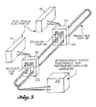
- FIG. 3 is a diagrammatic perspective view of the present passenger entertainment system showing transmitter loop and receiver loops coupled by means of core coupling in accordance with the first embodiment shown in FIG. 1.
- Briefly now turning to FIGS. 1 and 2 there will be seen first and second embodiments of transformer ferrite core coupling arrangements utilized between the passenger entertainment
system transmitter loop 38 andindividual receiver loops 30. The transformer core coupling of the embodiment of FIG. 1 is termed an E/E coupler since both the receiving portion of thetransformer core 50 and the transmitter portion of theferrite core coupler 52 are shaped in the form of an E. In the embodiment of FIG. 2 thereceiver portion 50 is E-shaped while thetransmitter core portion 55 is I-shaped and thus a consequence the embodiment of FIG. 2 is termed an E/I coupler. - Seat receivers 16 and 18 (and more receivers as necessary) have already been shown as represented by
numerals 16 and 18 in FIG. 1 of U.S. Patent No. 4,428,078 also assigned to The Boeing Company. A more detailed description of these receivers is given in the aforesaid patent and details thereof may be referred to as necessary and are incorporated herein by reference. Areceiver loop 30 also identified under thenumeral 30 is shown in U.S. Patent No. 4,428,078. In FIG. 3 of this application thetransmitter loop 38 is seen to be a multi-turn loop.Multi-turn transmitter loop 38 is located parallel to the seat track so that each of theindividual receiver loops 30 may be coupled through E/E or E/I couplers to thetransmitter loop 38. While the E/E coupler embodiment of FIG. 1 is shown in the system diagram of FIG. 3 for purposes of illustration, the E/I coupler of the embodiment of FIG. 2 may also be utilized.Guide springs 10 are shown in the embodiment of FIGS. 1 and 2 to permit insertion and retention of thereceiver core portions 50 withintrough 60.Troughs 60 includemembers 58 of iron or ferrite which form theU-shaped trough 60 surrounding the E/E or E/I couplers.Multi-turn transmitter loop 38 may be considered the primary of the transformer core E/E and E/I couplers, whilereceiver loop 30 may be considered the secondary of the couplers. It can be seen that the primary (transmitter) winding 38 is permanently mounted intrough 60 at the floor of the aircraft whilesecondary windings 30 carried by the E-shapedreceiver core portion 50 of the couplers can be placed at any position along theprimary transmitter loop 38 to form the present core coupled transmitter/receiver connectorless entertainment system. Thesecondary receiver loop 30 is lured onto theprimary transmitter loop 38 at the time the seats are installed. - The power transfer capability of the present system has been demonstrated to provide a typical power transfer of 10 watts with short term maximum power transfers of up to about 25 watts. The present system utilizing ferrite core configurations as shown in the first and second embodiments has provided the increased flux linkages between
transmitter loop 38 andreceiver loops 30 while providing for control of the radiated EMI fields.
Claims (4)
- A passenger entertainment system for transmission by simultaneous coupling of receiver power and intelligence information signals to a plurality of seat units, said system comprising:
transmitter means (23) for generating said receiver power and intelligence information signals;
receiver menas (16, 18) associated with each of said plurality of seat units;
a multi-turn transmitter loop (38) coupled to said transmitter means;
a multi-turn pick up loop (30) coupled to said receiver means associated with each of said plurality of seat units; characterized by
ferrite core transformer means comprising first (50) and second (52, 55) core portions, the first portion being part of said multi-turn pick up loop and the second portion being part of said multi-turn transmitter loop. - The invention according to claim 1 wherein said ferrite core transformer comprises first and second generally E-shaped cores.
- The invention according to claim 2 wherein said ferrite core transformer comprises a first generally E-shaped core and a second generally I-shaped core.
- The invention according to claim 2, wherein each of said multi-turn pick up loops is wound about the central leg portion of said first of said generally E-shaped cores, and said transmission line comprises a multi-turn loop disposed along the slots formed by the side leg portions of said second generally E-shaped cores.
Applications Claiming Priority (2)
| Application Number | Priority Date | Filing Date | Title |
|---|---|---|---|
| US908450 | 1986-09-17 | ||
| US06/908,450 US4736452A (en) | 1986-09-17 | 1986-09-17 | Core coupled transmitter/receiver loops for connectorless entertainment systems |
Publications (3)
| Publication Number | Publication Date |
|---|---|
| EP0260725A2 EP0260725A2 (en) | 1988-03-23 |
| EP0260725A3 EP0260725A3 (en) | 1989-07-12 |
| EP0260725B1 true EP0260725B1 (en) | 1993-01-27 |
Family
ID=25425824
Family Applications (1)
| Application Number | Title | Priority Date | Filing Date |
|---|---|---|---|
| EP87200326A Expired - Lifetime EP0260725B1 (en) | 1986-09-17 | 1987-02-25 | Core coupled transmitter/receiver loops for connectorless entertainment systems |
Country Status (3)
| Country | Link |
|---|---|
| US (1) | US4736452A (en) |
| EP (1) | EP0260725B1 (en) |
| DE (1) | DE3783841T2 (en) |
Families Citing this family (22)
| Publication number | Priority date | Publication date | Assignee | Title |
|---|---|---|---|---|
| EP0287645B1 (en) * | 1986-10-16 | 1992-01-02 | Sony Trans Com Inc. | Inductive coupled power system |
| US4853555A (en) * | 1988-04-21 | 1989-08-01 | The Boeing Company | Electrical power transfer system for aircraft passenger entertainment system |
| US4833338A (en) * | 1988-08-04 | 1989-05-23 | The Boeing Company | Ferroresonant regulator for inductively coupled power distribution system |
| US5012236A (en) * | 1989-05-26 | 1991-04-30 | Trovan Limited | Electromagnetic energy transmission and detection apparatus |
| EP0417542A1 (en) * | 1989-09-12 | 1991-03-20 | Siemens-Albis Aktiengesellschaft | Inductive coupling device for 2-wire lines |
| US5084864A (en) * | 1990-05-14 | 1992-01-28 | The Boeing Company | Broadband, inductively coupled, duplex, rf transmission system |
| US5293308A (en) * | 1991-03-26 | 1994-03-08 | Auckland Uniservices Limited | Inductive power distribution system |
| US5230085A (en) * | 1991-04-05 | 1993-07-20 | E-Systems, Inc. | Method and apparatus for wireless electromagnetic communication within a contained electromagnetic field |
| EP0646430B1 (en) * | 1992-06-18 | 2000-08-02 | Shinagawa Refractories Co., Ltd. | Refractory block for continuous casting |
| US6601798B2 (en) * | 2001-06-26 | 2003-08-05 | The Boeing Company | Seat track mounted passenger interface |
| US6585189B1 (en) * | 2001-12-07 | 2003-07-01 | Inflight Canada Inc. | Under floor air cooled housing system for aircraft passenger system electrical boxes and the like |
| US20060202084A1 (en) * | 2005-03-08 | 2006-09-14 | Smallhorn George R | Under floor housing system for aircraft passenger entertainment and communications systems |
| DE102005022367B4 (en) * | 2005-05-10 | 2021-05-20 | Sew-Eurodrive Gmbh & Co Kg | Contactlessly supplied consumer and system |
| DE102007003043A1 (en) * | 2007-01-20 | 2008-07-24 | Recaro Aircraft Seating Gmbh & Co. Kg | transforming device |
| GB2450526A (en) * | 2007-06-28 | 2008-12-31 | Tyco Electronics | Vehicle seat interconnect, method and vehicle seat data system |
| DE102008024217B4 (en) | 2008-05-19 | 2016-04-14 | Airbus Operations Gmbh | System for contactless data and energy transmission and use of such a system in an aircraft |
| DE102009019994B4 (en) | 2008-05-19 | 2020-08-13 | Airbus Operations Gmbh | Airplane with hybrid transmitters for contactless energy and data transmission |
| DE102009018111A1 (en) | 2009-04-20 | 2010-10-28 | Airbus Deutschland Gmbh | Easy to configure multifunction module for a passenger supply channel |
| DE102009053584A1 (en) | 2009-11-17 | 2011-05-19 | Airbus Operations Gmbh | Carrier system for receiving containers in a vehicle and use of a carrier system in an aircraft |
| DE102011017164A1 (en) * | 2011-04-15 | 2012-10-18 | Airbus Operations Gmbh | Equipment module for a vehicle and vehicle with a vehicle body having a cargo space |
| EP3130082A4 (en) * | 2014-04-08 | 2017-12-13 | Phitek Systems Limited | Improvement in, or relating to, passenger entertainment systems |
| EP4211775A4 (en) | 2020-09-10 | 2025-03-05 | Bitstrata Systems Inc. | INDUCTIVE POWER AND COMMUNICATION BUS |
Family Cites Families (10)
| Publication number | Priority date | Publication date | Assignee | Title |
|---|---|---|---|---|
| DE1108738B (en) * | 1959-07-03 | 1961-06-15 | Siemens Ag | Device for inductive transmission with low frequency |
| US3173119A (en) * | 1962-04-24 | 1965-03-09 | Clevite Corp | Method of making and adjusting transducer |
| US3461758A (en) * | 1967-01-16 | 1969-08-19 | Sola Basic Ind Inc | Method of making scrapless laminations for producing a plurality of units |
| US3553675A (en) * | 1968-08-08 | 1971-01-05 | John A Shaver | Floor covering for transmitting electromagnetic energy |
| DE2838138A1 (en) * | 1978-09-01 | 1980-03-13 | Bosch Gmbh Robert | Two=way TDM data transmission system - has station terminals inductively coupled via ring cores to ring main circuit |
| US4428078A (en) * | 1979-03-26 | 1984-01-24 | The Boeing Company | Wireless audio passenger entertainment system (WAPES) |
| US4352200A (en) * | 1979-10-09 | 1982-09-28 | Bell And Howell Company | Wireless aircraft passenger audio entertainment system |
| FR2492196A1 (en) * | 1980-10-15 | 1982-04-16 | Saulnier Dominique | Two-way information exchange between fixed and mobile assemblies - using physically and electrically isolated static transfer loop and magnetic induction information transfer |
| DE3106302A1 (en) * | 1981-02-20 | 1982-10-07 | Douw, Ray, 8201 Schonstett | Transmission of magnetic alternating fields |
| JPS58215832A (en) * | 1982-06-09 | 1983-12-15 | Sharp Corp | Data transmission system |
-
1986
- 1986-09-17 US US06/908,450 patent/US4736452A/en not_active Expired - Fee Related
-
1987
- 1987-02-25 EP EP87200326A patent/EP0260725B1/en not_active Expired - Lifetime
- 1987-02-25 DE DE8787200326T patent/DE3783841T2/en not_active Expired - Fee Related
Also Published As
| Publication number | Publication date |
|---|---|
| US4736452A (en) | 1988-04-05 |
| DE3783841T2 (en) | 1993-05-19 |
| DE3783841D1 (en) | 1993-03-11 |
| EP0260725A3 (en) | 1989-07-12 |
| EP0260725A2 (en) | 1988-03-23 |
Similar Documents
| Publication | Publication Date | Title |
|---|---|---|
| US4736452A (en) | Core coupled transmitter/receiver loops for connectorless entertainment systems | |
| EP0287645B1 (en) | Inductive coupled power system | |
| EP0260726B1 (en) | Passenger entertainment system having direct coupled seat receivers | |
| CN100442678C (en) | Inductive transfer of electrical energy | |
| US4239940A (en) | Carrier current communications system | |
| EP0447001B1 (en) | Current mode data bus digital communications system | |
| JP2722391B2 (en) | Transmission system | |
| EP0159916A2 (en) | Passive RF signals coupler for power lines | |
| US7232020B2 (en) | Telpher line with contactless energy and data transmission | |
| US5938151A (en) | Communication systems employing power cables for conveyor carriages | |
| IL181712A (en) | Arrangement of inductive couplers for data communication | |
| KR100670409B1 (en) | Non-contact Feeder | |
| EP0457379A2 (en) | Broadband, inductively coupled, duplex, RF transmission system | |
| US10919639B2 (en) | Aircraft comprising an electrical power distribution network | |
| JP3028896B2 (en) | Elevator signal transmission equipment | |
| KR102176288B1 (en) | Signalling system | |
| US10848341B2 (en) | Aircraft comprising a hybrid electrical power distribution and data communication network | |
| NL2019165B1 (en) | Coupling device and method for inductively coupling a load to a power line | |
| JPS6358415B2 (en) | ||
| JPH02207361A (en) | Data communication system utilizing inductive radio | |
| JPH054611U (en) | Antenna structure | |
| JPH03118725A (en) | Device for detecting operation of circuit breaker |
Legal Events
| Date | Code | Title | Description |
|---|---|---|---|
| PUAI | Public reference made under article 153(3) epc to a published international application that has entered the european phase |
Free format text: ORIGINAL CODE: 0009012 |
|
| AK | Designated contracting states |
Kind code of ref document: A2 Designated state(s): DE FR GB IT NL |
|
| PUAL | Search report despatched |
Free format text: ORIGINAL CODE: 0009013 |
|
| AK | Designated contracting states |
Kind code of ref document: A3 Designated state(s): DE FR GB IT NL |
|
| 17P | Request for examination filed |
Effective date: 19900105 |
|
| 17Q | First examination report despatched |
Effective date: 19910809 |
|
| GRAA | (expected) grant |
Free format text: ORIGINAL CODE: 0009210 |
|
| AK | Designated contracting states |
Kind code of ref document: B1 Designated state(s): DE FR GB IT NL |
|
| PG25 | Lapsed in a contracting state [announced via postgrant information from national office to epo] |
Ref country code: NL Effective date: 19930127 Ref country code: IT Free format text: LAPSE BECAUSE OF FAILURE TO SUBMIT A TRANSLATION OF THE DESCRIPTION OR TO PAY THE FEE WITHIN THE PRE;WARNING: LAPSES OF ITALIAN PATENTS WITH EFFECTIVE DATE BEFORE 2007 MAY HAVE OCCURRED AT ANY TIME BEFORE 2007. THE CORRECT EFFECTIVE DATE MAY BE DIFFERENT FROM THE ONE RECORDED.SCRIBED TIME-LIMIT Effective date: 19930127 |
|
| REF | Corresponds to: |
Ref document number: 3783841 Country of ref document: DE Date of ref document: 19930311 |
|
| ET | Fr: translation filed | ||
| NLV1 | Nl: lapsed or annulled due to failure to fulfill the requirements of art. 29p and 29m of the patents act | ||
| PLBE | No opposition filed within time limit |
Free format text: ORIGINAL CODE: 0009261 |
|
| STAA | Information on the status of an ep patent application or granted ep patent |
Free format text: STATUS: NO OPPOSITION FILED WITHIN TIME LIMIT |
|
| 26N | No opposition filed | ||
| PGFP | Annual fee paid to national office [announced via postgrant information from national office to epo] |
Ref country code: GB Payment date: 19940217 Year of fee payment: 8 |
|
| PGFP | Annual fee paid to national office [announced via postgrant information from national office to epo] |
Ref country code: FR Payment date: 19940225 Year of fee payment: 8 |
|
| PGFP | Annual fee paid to national office [announced via postgrant information from national office to epo] |
Ref country code: DE Payment date: 19940228 Year of fee payment: 8 |
|
| PG25 | Lapsed in a contracting state [announced via postgrant information from national office to epo] |
Ref country code: GB Effective date: 19950225 |
|
| GBPC | Gb: european patent ceased through non-payment of renewal fee |
Effective date: 19950225 |
|
| PG25 | Lapsed in a contracting state [announced via postgrant information from national office to epo] |
Ref country code: FR Effective date: 19951031 |
|
| PG25 | Lapsed in a contracting state [announced via postgrant information from national office to epo] |
Ref country code: DE Effective date: 19951101 |
|
| REG | Reference to a national code |
Ref country code: FR Ref legal event code: ST |