EP0260600A2 - High temperature nickel base alloy with improved stability - Google Patents
High temperature nickel base alloy with improved stability Download PDFInfo
- Publication number
- EP0260600A2 EP0260600A2 EP87113242A EP87113242A EP0260600A2 EP 0260600 A2 EP0260600 A2 EP 0260600A2 EP 87113242 A EP87113242 A EP 87113242A EP 87113242 A EP87113242 A EP 87113242A EP 0260600 A2 EP0260600 A2 EP 0260600A2
- Authority
- EP
- European Patent Office
- Prior art keywords
- alloy
- molybdenum
- silicon
- chromium
- grain size
- Prior art date
- Legal status (The legal status is an assumption and is not a legal conclusion. Google has not performed a legal analysis and makes no representation as to the accuracy of the status listed.)
- Granted
Links
Images

Classifications
-
- C—CHEMISTRY; METALLURGY
- C22—METALLURGY; FERROUS OR NON-FERROUS ALLOYS; TREATMENT OF ALLOYS OR NON-FERROUS METALS
- C22C—ALLOYS
- C22C19/00—Alloys based on nickel or cobalt
- C22C19/03—Alloys based on nickel or cobalt based on nickel
- C22C19/05—Alloys based on nickel or cobalt based on nickel with chromium
- C22C19/051—Alloys based on nickel or cobalt based on nickel with chromium and Mo or W
- C22C19/053—Alloys based on nickel or cobalt based on nickel with chromium and Mo or W with the maximum Cr content being at least 30% but less than 40%
Definitions
- the subject invention is directed to a nickel-chromium-molybdenum (Ni-Cr-Mo) alloy, and particularly to a Ni-Cr-Mo alloy which manifests a combination of exceptional impact strength and ductility upon exposure to elevated temperature, e.g., 1000°C (1832°F), for prolonged periods of time, 3,000 hours and more, while concomitantly affording high tensile and stress-rupture strengths plus good resistance to cyclic oxidation at high temperature.
- Ni-Cr-Mo nickel-chromium-molybdenum
- the present invention is an improvement over an established alloy disclosed in U.S. Patent 3,859,060.
- This patent encompasses a commercial alloy known as alloy 617, a product which has been produced and marketed for a number of years. Nominally, the 617 alloy contains about 22% chromium, 9% molybdenum, 1.2% aluminum, 0.3% titanium, 2% iron, 12.5% cobalt, 0.07% carbon, as well as other constituents, including 0.5% silicon, one or more of boron, manganese, magnesium, etc., the balance being nickel.
- alloy 617 include (i) good scaling resistance in oxidizing environments, including cyclic oxidation, at elevated temperature, (ii) excellent stress rupture strength, (iii) good tensile strength and ductility at both ambient and elevated temperatures, etc.
- Alloy 617 also possesses structural stability under, retrospectively speaking, what might be characterized as, comparatively speaking, moderate service conditions. But as it has turned out it is this characteristic which has given rise to a problem encountered commercially for certain intended and desired applications, e.g., high temperature gas feeder reactors (HTGR). This is to say, when the alloy was exposed to more stringent operating parameters of temperature (1800°F) and time (1000-3000+ hours) an undesirable degradation in structural stability occurred, though stress rupture, tensile and oxidation characteristics remained satisfactory.
- HTGR high temperature gas feeder reactors
- test temperature for stability study was usually not higher than 1600°F. And if higher temperatures were considered, short term exposure periods, circa 100 hours, were used. Longer term periods (circa 10,000 hours or more) were used but at the lower temperatures, i.e., not more than 1300°F-1400°F.
- the alloy contemplated herein contains about 7.5 to about 8.75 or 9% molybdenum, not more than 0.25% silicon, 0.05 to 0.15% carbon, about 19 or 20 to 30% chromium, about 7.5 to 20% cobalt, up to about 0.6% titanium, about 0.8 to 1.5% aluminum, up to about 0.006% boron, up to 0.1% zirconium, up to about 0.075% magnesium, and the balance essentially nickel.
- the term "balance” or "balance essentially” as used herein does not exclude the presence of other constituents, such as deoxidizing and cleansing elements, in amounts which do not adversely affect the basic properties otherwise characteristic of the alloy.
- any iron should not exceed 5%, and preferably does not exceed about 2%, to avoid subverting stress-rupture strength at temperatures such as 2000°F.
- Sulfur and phosphorus should be maintained at low levels, say, not more than 0.015% and 0.03% respectively.
- the presence of tungsten can be tolerated up to about 5%, and copper and manganese, if present, should not exceed 1%, respectively.
- the subject alloy is of the solid-solution type and further strengthened/hardened by the presence of carbides, gamma prime hardening being minor to insignificant.
- the carbides are of both the M23C6 and M6C types. The latter is more detrimental to room temperature ductility when occurring as continuous boundary particles. The higher levels of silicon tend to favor M6C formation. This, among other reasons, dictates that silicon be as low as practical though some amount will usually be present, say, 0.01%, with the best of commercial processing techniques.
- Molybdenum while up to 9% may be tolerated, should not exceed about 8.75% in an effort to effect optimum stability, as measured by Charpy-V-Notch impact strength and tensile ductility (standard parameters). This is particularly apropos at the higher silicon levels. As will be shown infra, molybdenum contents even at the 10% level detract from CVN impact strength, particularly at silicon levels circa 0.2-0.25%. Molybdenum contributes to elevated temperature strength and thus at least about 8% should preferably be present. Tests indicate that stress-rupture life is not impaired at the 2000°F level though a reduction (acceptable) may be experienced at 1600°F in comparison with Alloy 617. Given the foregoing, it is advantageous that the silicon and molybdenum be correlated as follows:
- Carbon contributes to stress-rupture strength but detracts from structural stability at high percentages. Low levels say, 0.03-0.04%, particularly at low molybdenum contents, result in an unnecessary loss of stress-rupture properties. Carbon also influences grain size by limiting the migration of grain boundaries. As carbon content increases, higher solution temperatures are required to achieve a given recrystallized grain diameter.
- chromium can be used up to 30%. But at such levels chromium together with molybdenum in particular may lead to forming an undesired volume of the embrittling sigma phase. It need not exceed 28% and in striving for structural stability a range of 19 to 23% is beneficial.
- annealing temper Even though very low annealing temper strictlyatures, say 1900-1975°F, offer a finer grain size but stress-rupture is unnecessarily adversely impacted. Accordingly, it is preferred that the annealing temperature be from 2025 to less than 2150°F with a range of 2025 to about 2125°F being preferred. While the grain size may be as coarse as ASTM 0 or 00 where the highest stress-rupture properties are necessary, it is preferred that the average size of the grains be finer than about ASTM 1 and coarser than about ASTM 5.5, e.g., ASTM 1.5 to ASTM 4.
- Annealing temperaturs were 2125°F and 2250F, respectfully, the specimens being held thereat for 1 hour, then air cooled.
- the alloys were exposed at 1832°F (100°C) for 100, 1000, 3000 and 10,000 hours and air cooled as set forth in TABLE II which sets forth the data obtained i.e., grain size, Rockwell hardness (Rb), yield (YS) and tensile strengths (TS), elongation (El.), Reduction of (RA) and Charpy V-Notch Impact Strength (CVN), the latter serving to assess structural stability.
- Alloys AA and BB resulted in markedly lower impact levels than Alloys 1-4, especially low silicon, low molybdenum Alloys 1 and 2, particularly when annealed at 2250°F.
- Alloys AA and BB had, comparatively speaking, high percentages of both silicon and molybdenum together with a coarse grain varying from ASTM 0 to 1.
- Alloys CC and DD while better than AA and BB due, it is deemed to much lower silicon percentages, were still much inferior to Alloys 1-4 given a 2125°F anneal.
- Tables IV and V pertain to a 22,000 lb. commercial size heat which was produced using vacuum induction melting followed by electroslag refining. The material was processed into 3/4" dia. hot rolled rounds for testing and evaluation. The as-hot-finished rod stock was used for an annealing evaluation/grain size study evaluation.
- the composition of the heat Alloy 5, is given below in Table IV with annealing temperature and grain size reported in Table V.
- Table V given the chemistry in IV, an annealing temperature above 2175°, e.g. 2200°F, and above resulted in an excessively coarse grain structure whereas annealing at 2000°F gave too fine a grain.
- a final annealing should be conducted above 2000°F to about 2150°F.
- Table VI The effect of annealing temperatures (2000°F, 2050°F, 2125°F, 2250°F) and grain size on structural stability as indicated by the Charpy-V-Notch test size is shown in Table VI, and is more graphically depicted in Figure 1.
- Table VI includes tensile properties, stress rupture results being given in Table VII.
- the impact energy data at 1832°F in Table VI confirms the superior results of a commercial size heat of an alloy composition/annealing temperature within the invention.
- Alloy 5 manifested a borderline impact strength of 32 ft. lbs., versus, for example, 58 ft. lbs., when annealed at 2125°F. It is deemed that the impact energy level at 1832°F and 10,000 hours exposure should be at least 40 ft. lbs. and preferably 50 ft. lbs. although, as suggested above 30 ft. lbs. is marginally acceptable.
- the 2000°F anneal afforded high impact strength at 10,000 hours but as shown in Table VII stress-rupture life suffured, being 23.9 hours vs. 50 hours when annealed at 2125°F. The difference is even more striking at the 2000°F test condition.
- GSMA Gas shielded metal arc
- plate 0.345 inch thick taken from hot band of Alloy 5 was annealed at both 1800°F and 2200°F to provide material of different grain sizes.
- the 1800°F would not cause a change in grain size, the original grain size being ASTM 2.5).
- the 2200°F anneal (which is not a recommended annealing treatment) gave a grain size beyond about ASTM 00. This was done with the purpose that an alloy of limited weldability, given the variation in grain size, would be expected to manifest some variation in base metal microfissuring.
- a weldment was deposited between two specimens of the plate (one of each anneal) by GMAW - spray transfer with 0.045 inch diameter filler metal from Alloy 5, the following parameters being used.
- Filler metals of Alloy 5 were made in wire diameters of 0.045 and 0.093 inch and then used in Gas Metal Arc Welding (GMAW) spray transfer and Gas Tungsten Arc Welding (GTAW), respectively.
- GMAW Gas Metal Arc Welding
- GTAW Gas Tungsten Arc Welding
- a third wire, 0.125 inch in diameter was used as a core wire for producing a covered electrode for Shielded Metal Arc Welding (SMAW).
- Room temperature impact data from weldments of each of the GMAW, GTAW and SMAW are reported in Table VIII with mechanical properties being given in Table IX.
- GTAW Diameter - 3/32 Electrode Type/Diameter - 2% Thoriated Tungsten / 3/32" Current - 180 amperes DCEN Voltage - 12-14 volts Shielding Gas - Argon Flow Rate - 25 cfh Joint Design - V-Butt 60° Opening Position - Flat - 1G Travel Speed - 4-6 ipm (Manual)
- the subject alloy can be melted in conventional melting equipment such as air or vacuum induction furnaces or electroslag remelt furnaces. Vacuum processing is preferred.
- the alloy is useful for application in which its predecessor has been used, including gas turbine components such as combustion liners.
Abstract
Description
- The subject invention is directed to a nickel-chromium-molybdenum (Ni-Cr-Mo) alloy, and particularly to a Ni-Cr-Mo alloy which manifests a combination of exceptional impact strength and ductility upon exposure to elevated temperature, e.g., 1000°C (1832°F), for prolonged periods of time, 3,000 hours and more, while concomitantly affording high tensile and stress-rupture strengths plus good resistance to cyclic oxidation at high temperature.
- Essentially, the present invention is an improvement over an established alloy disclosed in U.S. Patent 3,859,060. This patent encompasses a commercial alloy known as alloy 617, a product which has been produced and marketed for a number of years. Nominally, the 617 alloy contains about 22% chromium, 9% molybdenum, 1.2% aluminum, 0.3% titanium, 2% iron, 12.5% cobalt, 0.07% carbon, as well as other constituents, including 0.5% silicon, one or more of boron, manganese, magnesium, etc., the balance being nickel. The virtues of alloy 617 include (i) good scaling resistance in oxidizing environments, including cyclic oxidation, at elevated temperature, (ii) excellent stress rupture strength, (iii) good tensile strength and ductility at both ambient and elevated temperatures, etc.
- Alloy 617 also possesses structural stability under, retrospectively speaking, what might be characterized as, comparatively speaking, moderate service conditions. But as it has turned out it is this characteristic which has given rise to a problem encountered commercially for certain intended and desired applications, e.g., high temperature gas feeder reactors (HTGR). This is to say, when the alloy was exposed to more stringent operating parameters of temperature (1800°F) and time (1000-3000+ hours) an undesirable degradation in structural stability occurred, though stress rupture, tensile and oxidation characteristics remained satisfactory.
- Apparently, what happened was that prior to the 1800°F/1000+ hour operating conditions, the test temperature for stability study was usually not higher than 1600°F. And if higher temperatures were considered, short term exposure periods, circa 100 hours, were used. Longer term periods (circa 10,000 hours or more) were used but at the lower temperatures, i.e., not more than 1300°F-1400°F.
- Apart from temperature/time operating conditions, the problem would not surface because in many applications structural stability was not critically important, e.g., boats used for catalyst-grid supports, heat treating baskets, reduction boats used in refining certain metals, etc.
- Accordingly, the problem became one of ascertaining the cause(s) for the stability deterioration at upwards of 1800°F-2,000°F for periods well exceeding 1000 hours, and evolving, if possible, a new alloy which would result in enhanced stability under such operating conditions but without incurring a detrimental sacrifice in stress-rupture/oxidation/tensile properties.
- We have found that silicon and molybdenum when present to the excess can adversely affect the stability of Alloy 617. We have also found that carbon, if beyond the range specified below herein, can, depending upon chemistry, exercise a negative influence. Moreover, it has been determined that grain size plays a significant, if not the major, role, grain size being influenced by composition and processing, particularly annealing treatment. Grain size, chemistry, particularly silicon, molybdenum and carbon, and annealing temperature are interrelated or interdependent as will become more clear infra. The invention herein involves the critical controlling of these related aspects.
- Generally speaking and in accordance with the present invention, the alloy contemplated herein contains about 7.5 to about 8.75 or 9% molybdenum, not more than 0.25% silicon, 0.05 to 0.15% carbon, about 19 or 20 to 30% chromium, about 7.5 to 20% cobalt, up to about 0.6% titanium, about 0.8 to 1.5% aluminum, up to about 0.006% boron, up to 0.1% zirconium, up to about 0.075% magnesium, and the balance essentially nickel. The term "balance" or "balance essentially" as used herein does not exclude the presence of other constituents, such as deoxidizing and cleansing elements, in amounts which do not adversely affect the basic properties otherwise characteristic of the alloy. In this connection, any iron should not exceed 5%, and preferably does not exceed about 2%, to avoid subverting stress-rupture strength at temperatures such as 2000°F. Sulfur and phosphorus should be maintained at low levels, say, not more than 0.015% and 0.03% respectively. In respect of other elements, the presence of tungsten can be tolerated up to about 5%, and copper and manganese, if present, should not exceed 1%, respectively.
- In carrying the invention into practice, and in endeavoring to achieve consistent results, care must be exercised in respect of compositional control; in particular, molybdenum, silicon and carbon should be interrelated and controlled as indicated hereinafter. Silicon has been found to act subversively, particularly at high molybdenum and carbon contents. In retrospect, virgin materials were used in the research stage of Alloy 617. Thus, silicon was at a low level. But in commercial production scrap materials are used wherever possible to reduce costs. As a consequence, higher percentages of silicon would have been employed since the overall adverse effect of silicon in conjunction with molybdenum/carbon, grain size/annealing temperature at 1800-2000°F was neither known nor understood prior to the present invention. As indicated above, a typical commercial nominal silicon content is 0.5% and there are current commercial "specifications" where the silicon can be as high as 1% with molybdenum being as high as 11%.
- Morphologically speaking, the subject alloy is of the solid-solution type and further strengthened/hardened by the presence of carbides, gamma prime hardening being minor to insignificant. The carbides are of both the M₂₃C₆ and M₆C types. The latter is more detrimental to room temperature ductility when occurring as continuous boundary particles. The higher levels of silicon tend to favor M₆C formation. This, among other reasons, dictates that silicon be as low as practical though some amount will usually be present, say, 0.01%, with the best of commercial processing techniques.
- Molybdenum, while up to 9% may be tolerated, should not exceed about 8.75% in an effort to effect optimum stability, as measured by Charpy-V-Notch impact strength and tensile ductility (standard parameters). This is particularly apropos at the higher silicon levels. As will be shown infra, molybdenum contents even at the 10% level detract from CVN impact strength, particularly at silicon levels circa 0.2-0.25%. Molybdenum contributes to elevated temperature strength and thus at least about 8% should preferably be present. Tests indicate that stress-rupture life is not impaired at the 2000°F level though a reduction (acceptable) may be experienced at 1600°F in comparison with Alloy 617. Given the foregoing, it is advantageous that the silicon and molybdenum be correlated as follows:

- With regard to carbon, a range of 0.05 to 0.1%, particularly 0.05 to 0.07%, is advantageous. Carbon contributes to stress-rupture strength but detracts from structural stability at high percentages. Low levels say, 0.03-0.04%, particularly at low molybdenum contents, result in an unnecessary loss of stress-rupture properties. Carbon also influences grain size by limiting the migration of grain boundaries. As carbon content increases, higher solution temperatures are required to achieve a given recrystallized grain diameter.
- Where optimum corrosion resistance is required, chromium can be used up to 30%. But at such levels chromium together with molybdenum in particular may lead to forming an undesired volume of the embrittling sigma phase. It need not exceed 28% and in striving for structural stability a range of 19 to 23% is beneficial.
- In addition to the foregoing, it has been determined that grain size has a market influence on toughness. Chemistry and processing control, mainly annealing temperature, are interdependent in respect of grain size. While it has been customary to final anneal Alloy 617 at 2175 to 2200°F commercially, in accordance with the present invention annealing should be conducted below about 2150°F and above 2000°F. The effect of annealing temperature on a commercial size, 22,000 lbs., melt is given in Tables IV and V. An annealing temperature of, say 2200°F, promotes the formation of the coarser grains but stress-rupture properties are higher. On the other hand, very low annealing temperatures, say 1900-1975°F, offer a finer grain size but stress-rupture is unnecessarily adversely impacted. Accordingly, it is preferred that the annealing temperature be from 2025 to less than 2150°F with a range of 2025 to about 2125°F being preferred. While the grain size may be as coarse as
ASTM 0 or 00 where the highest stress-rupture properties are necessary, it is preferred that the average size of the grains be finer than about ASTM 1 and coarser than about ASTM 5.5, e.g., ASTM 1.5 to ASTM 4. - To give those skilled in the art a better appreciation of the invention, the following information and data are given:
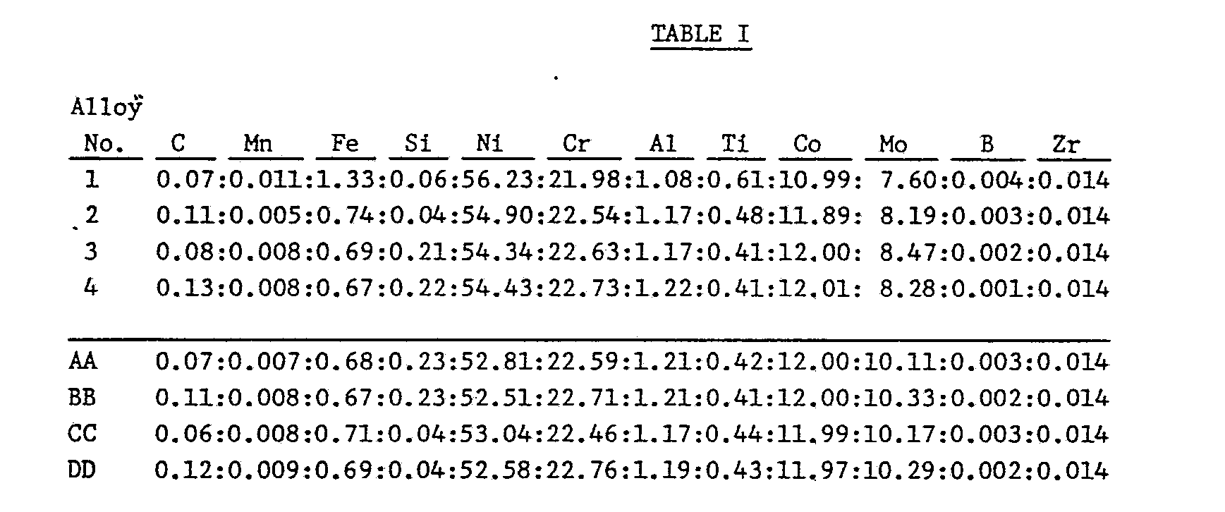
- 14 kg vacuum induction laboratory heats were made, then forged at about 2200°F to 13/16 inch squares for hot rolling (2200°F) to 9/16 inch rounds. Respresentative compositions are given in TABLE I. Alloys AA through DD are outside the invention.
- Annealing temperaturs were 2125°F and 2250F, respectfully, the specimens being held thereat for 1 hour, then air cooled. The alloys were exposed at 1832°F (100°C) for 100, 1000, 3000 and 10,000 hours and air cooled as set forth in TABLE II which sets forth the data obtained i.e., grain size, Rockwell hardness (Rb), yield (YS) and tensile strengths (TS), elongation (El.), Reduction of (RA) and Charpy V-Notch Impact Strength (CVN), the latter serving to assess structural stability.


- Concerning the data above given, Alloys AA and BB resulted in markedly lower impact levels than Alloys 1-4, especially low silicon, low molybdenum Alloys 1 and 2, particularly when annealed at 2250°F. Alloys AA and BB had, comparatively speaking, high percentages of both silicon and molybdenum together with a coarse grain varying from ASTM 0 to 1. Alloys CC and DD while better than AA and BB due, it is deemed to much lower silicon percentages, were still much inferior to Alloys 1-4 given a 2125°F anneal. While the Charpy-V-Notch impact data for Alloys AA-DD appear to be good for the 2125°F anneal, our investigations have indicated that with commercial size heats impact strengths for alloys of high molybdenum significantly drop off. Also, there is danger/risk of not controlling annealing temperature and the 2250°F anneal reflects what can be expected in terms of anticipated structural stability.
- In Table III are reported stress rupture data for the Alloys In Table I. In this case the annealing temperature was 2150°F. While the stress (5KSI) used at 1832°F is fairly high for that temperature level, stress rupture properties for the alloys within the invention are satisfactory.

- Tables IV and V pertain to a 22,000 lb. commercial size heat which was produced using vacuum induction melting followed by electroslag refining. The material was processed into 3/4" dia. hot rolled rounds for testing and evaluation. The as-hot-finished rod stock was used for an annealing evaluation/grain size study evaluation. The composition of the heat Alloy 5, is given below in Table IV with annealing temperature and grain size reported in Table V.

- The effect of annealing temperatures (2000°F, 2050°F, 2125°F, 2250°F) and grain size on structural stability as indicated by the Charpy-V-Notch test size is shown in Table VI, and is more graphically depicted in Figure 1. Table VI includes tensile properties, stress rupture results being given in Table VII.


- The impact energy data at 1832°F in Table VI confirms the superior results of a commercial size heat of an alloy composition/annealing temperature within the invention. For an exposure period of 10,000 hours and an annealing temperature of 2250°F, Alloy 5 manifested a borderline impact strength of 32 ft. lbs., versus, for example, 58 ft. lbs., when annealed at 2125°F. It is deemed that the impact energy level at 1832°F and 10,000 hours exposure should be at least 40 ft. lbs. and preferably 50 ft. lbs. although, as suggested above 30 ft. lbs. is marginally acceptable. The 2000°F anneal afforded high impact strength at 10,000 hours but as shown in Table VII stress-rupture life suffured, being 23.9 hours vs. 50 hours when annealed at 2125°F. The difference is even more striking at the 2000°F test condition.
- Apart from the foregoing and based on welding data at hand, the instant alloy is deemed readily weldable using conventional welding practices as will be demonstrated below. As a matter of general observation from the tests conducted, no base metal microfissuring was observed in the heat affected zone (HAZ) of a Gas Metal Arc (GMA) weldment. This test resulted in a slight loss of strength in the as-welded and annealed condition as would be expected but, more importantly, the deposit exhibited greatly improved ductility and impact strength after exposure to aging temperature, giving corresponding properties for commercial Alloy 617. Gas shielded metal arc (GSMA) deposits made using filler metals of the invention alloy as a core wire in a coated welded electrode manifested improved ductility and impact strength in comparison with weld deposits using filler metal of commercial Alloy 617. In this connection, a significant loss of ductility was experienced after exposure and this was attributed to the elements, notably carbon and silicon, introduced in the deposit by the flux coating. It is deemed that such constituents are sufficient to induce high temperature reaction which are believed responsible for the ductility loss in the deposit.
- With regard to the welding tests, plate 0.345 inch thick taken from hot band of Alloy 5 was annealed at both 1800°F and 2200°F to provide material of different grain sizes. (The 1800°F would not cause a change in grain size, the original grain size being ASTM 2.5). The 2200°F anneal (which is not a recommended annealing treatment) gave a grain size beyond about ASTM 00. This was done with the purpose that an alloy of limited weldability, given the variation in grain size, would be expected to manifest some variation in base metal microfissuring. A weldment was deposited between two specimens of the plate (one of each anneal) by GMAW - spray transfer with 0.045 inch diameter filler metal from Alloy 5, the following parameters being used.
Diameter - 0.045" Joint Design - V-Butt - 60° Opening
Current - 220 amps Voltage - 32 volts
Wirefeed - 423 ipm Position - Flat - 1G
Flow Rate - 50 cfh Travel Speed - 12 - 15 ipm (Manual)
Transverse face, root and side bend specimens, centered in both the weld and heat affected zones (HAZ) were tested, (i.e., usually 3 specimens were taken from the weld plate per test conditions. Liquid penetration inspection revealed no fissuring in the welds or the HAZ. Using specimens bent over a thickness twice that of the specimens (2T), only one face bend test showed any fissuring; however, the fissures did not intersect the fusion line and were thus deemed not weld related but were probably due to plate surface. No other fissuring was detected in either liquid penetration or metallographic examination. - Filler metals of Alloy 5 were made in wire diameters of 0.045 and 0.093 inch and then used in Gas Metal Arc Welding (GMAW) spray transfer and Gas Tungsten Arc Welding (GTAW), respectively. A third wire, 0.125 inch in diameter was used as a core wire for producing a covered electrode for Shielded Metal Arc Welding (SMAW). Room temperature impact data from weldments of each of the GMAW, GTAW and SMAW are reported in Table VIII with mechanical properties being given in Table IX. The parameters for the GTAW and SMAW were as follows:
GTAW
Diameter - 3/32"
Electrode Type/Diameter - 2% Thoriated Tungsten / 3/32"
Current - 180 amperes DCEN
Voltage - 12-14 volts
Shielding Gas - Argon
Flow Rate - 25 cfh
Joint Design - V-Butt 60° Opening
Position - Flat - 1G
Travel Speed - 4-6 ipm (Manual)
SMAW
Diameter - 1/8"
Current - 90 amperes
Voltage - 23 volts
Joint Design - V-Butt - 60° Opening
Position - Flat - 1G
Travel Speed - 10-12 ipm (Manual)

- The subject alloy can be melted in conventional melting equipment such as air or vacuum induction furnaces or electroslag remelt furnaces. Vacuum processing is preferred. The alloy is useful for application in which its predecessor has been used, including gas turbine components such as combustion liners.
- Although the present invention has been described in conjunction with preferred embodiments, it is to be understood that modifications and variations may be resorted to without departing from the spirit and scope of the invention as claimed herein, as those skilled in the art will readily understand. Such modifications and variations are considered to be within the purview and scope of the invention.
Claims (10)

Priority Applications (1)
| Application Number | Priority Date | Filing Date | Title |
|---|---|---|---|
| AT87113242T ATE76443T1 (en) | 1986-09-12 | 1987-09-10 | HIGH TEMPERATURE RESISTANT NICKEL BASED ALLOY WITH INCREASED STABILITY. |
Applications Claiming Priority (2)
| Application Number | Priority Date | Filing Date | Title |
|---|---|---|---|
| US06/907,055 US4750954A (en) | 1986-09-12 | 1986-09-12 | High temperature nickel base alloy with improved stability |
| US907055 | 1986-09-12 |
Publications (3)
| Publication Number | Publication Date |
|---|---|
| EP0260600A2 true EP0260600A2 (en) | 1988-03-23 |
| EP0260600A3 EP0260600A3 (en) | 1989-01-18 |
| EP0260600B1 EP0260600B1 (en) | 1992-05-20 |
Family
ID=25423441
Family Applications (1)
| Application Number | Title | Priority Date | Filing Date |
|---|---|---|---|
| EP87113242A Expired - Lifetime EP0260600B1 (en) | 1986-09-12 | 1987-09-10 | High temperature nickel base alloy with improved stability |
Country Status (12)
| Country | Link |
|---|---|
| US (1) | US4750954A (en) |
| EP (1) | EP0260600B1 (en) |
| JP (1) | JPS6376840A (en) |
| AT (1) | ATE76443T1 (en) |
| AU (1) | AU592451B2 (en) |
| BR (1) | BR8704718A (en) |
| CA (1) | CA1317130C (en) |
| DE (1) | DE3779233D1 (en) |
| ES (1) | ES2032790T3 (en) |
| FI (1) | FI873950A (en) |
| IL (1) | IL83869A (en) |
| IN (1) | IN170403B (en) |
Cited By (4)
| Publication number | Priority date | Publication date | Assignee | Title |
|---|---|---|---|---|
| WO2000014290A1 (en) * | 1998-09-04 | 2000-03-16 | Inco Alloys International, Inc. | Advanced high temperature corrosion resistant alloy |
| EP2511389A1 (en) * | 2009-12-10 | 2012-10-17 | Sumitomo Metal Industries, Ltd. | Austenitic heat-resistant alloy |
| EP2743362A1 (en) * | 2011-08-09 | 2014-06-18 | Nippon Steel & Sumitomo Metal Corporation | Ni-BASED HEAT-RESISTANT ALLOY |
| AT14576U1 (en) * | 2014-08-20 | 2016-01-15 | Plansee Se | Metallization for a thin film device, method of making the same and sputtering target |
Families Citing this family (4)
| Publication number | Priority date | Publication date | Assignee | Title |
|---|---|---|---|---|
| US5372662A (en) * | 1992-01-16 | 1994-12-13 | Inco Alloys International, Inc. | Nickel-base alloy with superior stress rupture strength and grain size control |
| US6302649B1 (en) * | 1999-10-04 | 2001-10-16 | General Electric Company | Superalloy weld composition and repaired turbine engine component |
| JP4585578B2 (en) * | 2008-03-31 | 2010-11-24 | 株式会社東芝 | Ni-based alloy for steam turbine turbine rotor and steam turbine turbine rotor |
| US20160199939A1 (en) * | 2015-01-09 | 2016-07-14 | Lincoln Global, Inc. | Hot wire laser cladding process and consumables used for the same |
Citations (1)
| Publication number | Priority date | Publication date | Assignee | Title |
|---|---|---|---|---|
| FR2149935A5 (en) * | 1971-08-06 | 1973-03-30 | Wiggin & Co Ltd Henry |
Family Cites Families (1)
| Publication number | Priority date | Publication date | Assignee | Title |
|---|---|---|---|---|
| JPS5227614A (en) * | 1975-08-27 | 1977-03-02 | Matsushita Electric Ind Co Ltd | Magnetic sheet playback device |
-
1986
- 1986-09-12 US US06/907,055 patent/US4750954A/en not_active Expired - Lifetime
-
1987
- 1987-09-03 CA CA000546062A patent/CA1317130C/en not_active Expired - Fee Related
- 1987-09-07 IN IN648/MAS/87A patent/IN170403B/en unknown
- 1987-09-10 DE DE8787113242T patent/DE3779233D1/en not_active Expired - Fee Related
- 1987-09-10 AT AT87113242T patent/ATE76443T1/en not_active IP Right Cessation
- 1987-09-10 ES ES198787113242T patent/ES2032790T3/en not_active Expired - Lifetime
- 1987-09-10 EP EP87113242A patent/EP0260600B1/en not_active Expired - Lifetime
- 1987-09-11 AU AU78284/87A patent/AU592451B2/en not_active Ceased
- 1987-09-11 BR BR8704718A patent/BR8704718A/en unknown
- 1987-09-11 IL IL83869A patent/IL83869A/en not_active IP Right Cessation
- 1987-09-11 FI FI873950A patent/FI873950A/en not_active Application Discontinuation
- 1987-09-11 JP JP62228235A patent/JPS6376840A/en active Pending
Patent Citations (1)
| Publication number | Priority date | Publication date | Assignee | Title |
|---|---|---|---|---|
| FR2149935A5 (en) * | 1971-08-06 | 1973-03-30 | Wiggin & Co Ltd Henry |
Cited By (10)
| Publication number | Priority date | Publication date | Assignee | Title |
|---|---|---|---|---|
| WO2000014290A1 (en) * | 1998-09-04 | 2000-03-16 | Inco Alloys International, Inc. | Advanced high temperature corrosion resistant alloy |
| US6761854B1 (en) | 1998-09-04 | 2004-07-13 | Huntington Alloys Corporation | Advanced high temperature corrosion resistant alloy |
| EP2511389A1 (en) * | 2009-12-10 | 2012-10-17 | Sumitomo Metal Industries, Ltd. | Austenitic heat-resistant alloy |
| EP2511389A4 (en) * | 2009-12-10 | 2013-08-28 | Nippon Steel & Sumitomo Metal Corp | Austenitic heat-resistant alloy |
| US8808473B2 (en) | 2009-12-10 | 2014-08-19 | Nippon Steel & Sumitomo Metal Corporation | Austenitic heat resistant alloy |
| EP2743362A1 (en) * | 2011-08-09 | 2014-06-18 | Nippon Steel & Sumitomo Metal Corporation | Ni-BASED HEAT-RESISTANT ALLOY |
| EP2743362A4 (en) * | 2011-08-09 | 2015-04-15 | Nippon Steel & Sumitomo Metal Corp | Ni-BASED HEAT-RESISTANT ALLOY |
| US9328403B2 (en) | 2011-08-09 | 2016-05-03 | Nippon Steel & Sumitomo Metal Corporation | Ni-based heat resistant alloy |
| AT14576U1 (en) * | 2014-08-20 | 2016-01-15 | Plansee Se | Metallization for a thin film device, method of making the same and sputtering target |
| US11047038B2 (en) | 2014-08-20 | 2021-06-29 | Plansee Se | Metallization for a thin-film component, process for the production thereof and sputtering target |
Also Published As
| Publication number | Publication date |
|---|---|
| AU592451B2 (en) | 1990-01-11 |
| FI873950A0 (en) | 1987-09-11 |
| IL83869A (en) | 1991-06-10 |
| CA1317130C (en) | 1993-05-04 |
| AU7828487A (en) | 1988-03-17 |
| ATE76443T1 (en) | 1992-06-15 |
| ES2032790T3 (en) | 1993-03-01 |
| US4750954A (en) | 1988-06-14 |
| BR8704718A (en) | 1988-05-03 |
| EP0260600A3 (en) | 1989-01-18 |
| JPS6376840A (en) | 1988-04-07 |
| FI873950A (en) | 1988-03-13 |
| IN170403B (en) | 1992-03-21 |
| EP0260600B1 (en) | 1992-05-20 |
| IL83869A0 (en) | 1988-02-29 |
| DE3779233D1 (en) | 1992-06-25 |
Similar Documents
| Publication | Publication Date | Title |
|---|---|---|
| CA2660107C (en) | Welding alloy and articles for use in welding, weldments and method for producing weldments | |
| EP0051979B1 (en) | Nickel-base welding alloy | |
| CA1063836A (en) | Oxidation resistant ni-cr-al-y alloys and methods of making the same | |
| EP1107846B1 (en) | Nickel-chromium-iron welding alloy | |
| EP0260600A2 (en) | High temperature nickel base alloy with improved stability | |
| EP0039450B1 (en) | Hard facing nickel-base alloy | |
| US4846885A (en) | High molybdenum nickel-base alloy | |
| CA1063838A (en) | Nickel-chromium filler metal | |
| JPH06142980A (en) | Welding material for austenitic stainless steel having excellent high-temperature strength | |
| JPH044079B2 (en) | ||
| JPH11285890A (en) | High c/high cr-ni based welding rod | |
| US2772963A (en) | Inert-gas shielded-arc welding of 90-10 type copper-nickel material | |
| AU624463B2 (en) | Tantalum-containing superalloys | |
| JP3009658B2 (en) | Welding material for high Cr steel | |
| CA1109297A (en) | Age hardenable nickel superalloy welding wires containing manganese | |
| JPH08174269A (en) | Filler metal for ni base high cr alloy | |
| US20240018635A1 (en) | Use of a titanium-free nickel-chromium-iron-molybdenum alloy | |
| JP3406663B2 (en) | Welding material for spheroidal graphite cast iron | |
| JPH0970688A (en) | Coated arc welding electrode | |
| JP2000326089A (en) | WELDING FILLER METAL OF Ni-Cr-W BASED ALLOY | |
| JP2022102850A (en) | SOLID WIRE FOR GAS SHIELD ARC WELDING USED FOR WELD OF LOW Si STEEL, JOINTING METHOD OF LOW Si STEEL, AND REPAIR METHOD OF LOW Si STEEL | |
| Lau et al. | Fusion welding of stainless steels | |
| Manikandan et al. | Welding of Alloy C-276 | |
| JPH03122245A (en) | High strength aluminum alloy for welding excellent in stress corrosion cracking resistance | |
| EP0120675A1 (en) | Nickel-iron welding alloy |
Legal Events
| Date | Code | Title | Description |
|---|---|---|---|
| PUAI | Public reference made under article 153(3) epc to a published international application that has entered the european phase |
Free format text: ORIGINAL CODE: 0009012 |
|
| AK | Designated contracting states |
Kind code of ref document: A2 Designated state(s): AT BE CH DE ES FR GB IT LI SE |
|
| RBV | Designated contracting states (corrected) |
Designated state(s): AT BE DE ES FR GB IT SE |
|
| PUAL | Search report despatched |
Free format text: ORIGINAL CODE: 0009013 |
|
| AK | Designated contracting states |
Kind code of ref document: A3 Designated state(s): AT BE DE ES FR GB IT SE |
|
| 17P | Request for examination filed |
Effective date: 19890706 |
|
| 17Q | First examination report despatched |
Effective date: 19910115 |
|
| GRAA | (expected) grant |
Free format text: ORIGINAL CODE: 0009210 |
|
| AK | Designated contracting states |
Kind code of ref document: B1 Designated state(s): AT BE DE ES FR GB IT SE |
|
| REF | Corresponds to: |
Ref document number: 76443 Country of ref document: AT Date of ref document: 19920615 Kind code of ref document: T |
|
| REF | Corresponds to: |
Ref document number: 3779233 Country of ref document: DE Date of ref document: 19920625 |
|
| ET | Fr: translation filed | ||
| PGFP | Annual fee paid to national office [announced via postgrant information from national office to epo] |
Ref country code: AT Payment date: 19920811 Year of fee payment: 6 |
|
| PGFP | Annual fee paid to national office [announced via postgrant information from national office to epo] |
Ref country code: SE Payment date: 19920814 Year of fee payment: 6 |
|
| ITF | It: translation for a ep patent filed |
Owner name: SOCIETA' ITALIANA BREVETTI S.P.A. |
|
| PGFP | Annual fee paid to national office [announced via postgrant information from national office to epo] |
Ref country code: BE Payment date: 19920821 Year of fee payment: 6 |
|
| PGFP | Annual fee paid to national office [announced via postgrant information from national office to epo] |
Ref country code: ES Payment date: 19920911 Year of fee payment: 6 |
|
| REG | Reference to a national code |
Ref country code: ES Ref legal event code: FG2A Ref document number: 2032790 Country of ref document: ES Kind code of ref document: T3 |
|
| PLBE | No opposition filed within time limit |
Free format text: ORIGINAL CODE: 0009261 |
|
| STAA | Information on the status of an ep patent application or granted ep patent |
Free format text: STATUS: NO OPPOSITION FILED WITHIN TIME LIMIT |
|
| 26N | No opposition filed | ||
| PG25 | Lapsed in a contracting state [announced via postgrant information from national office to epo] |
Ref country code: AT Effective date: 19930910 |
|
| PG25 | Lapsed in a contracting state [announced via postgrant information from national office to epo] |
Ref country code: SE Effective date: 19930911 Ref country code: ES Free format text: LAPSE BECAUSE OF EXPIRATION OF PROTECTION Effective date: 19930911 |
|
| PG25 | Lapsed in a contracting state [announced via postgrant information from national office to epo] |
Ref country code: BE Effective date: 19930930 |
|
| BERE | Be: lapsed |
Owner name: INCO ALLOYS INTERNATIONAL INC. Effective date: 19930930 |
|
| EUG | Se: european patent has lapsed |
Ref document number: 87113242.9 Effective date: 19940410 |
|
| REG | Reference to a national code |
Ref country code: ES Ref legal event code: FD2A Effective date: 19990601 |
|
| REG | Reference to a national code |
Ref country code: GB Ref legal event code: IF02 |
|
| PGFP | Annual fee paid to national office [announced via postgrant information from national office to epo] |
Ref country code: FR Payment date: 20040812 Year of fee payment: 18 |
|
| PGFP | Annual fee paid to national office [announced via postgrant information from national office to epo] |
Ref country code: GB Payment date: 20040817 Year of fee payment: 18 |
|
| PGFP | Annual fee paid to national office [announced via postgrant information from national office to epo] |
Ref country code: DE Payment date: 20040818 Year of fee payment: 18 |
|
| PG25 | Lapsed in a contracting state [announced via postgrant information from national office to epo] |
Ref country code: IT Free format text: LAPSE BECAUSE OF NON-PAYMENT OF DUE FEES;WARNING: LAPSES OF ITALIAN PATENTS WITH EFFECTIVE DATE BEFORE 2007 MAY HAVE OCCURRED AT ANY TIME BEFORE 2007. THE CORRECT EFFECTIVE DATE MAY BE DIFFERENT FROM THE ONE RECORDED. Effective date: 20050910 Ref country code: GB Free format text: LAPSE BECAUSE OF NON-PAYMENT OF DUE FEES Effective date: 20050910 |
|
| PG25 | Lapsed in a contracting state [announced via postgrant information from national office to epo] |
Ref country code: DE Free format text: LAPSE BECAUSE OF NON-PAYMENT OF DUE FEES Effective date: 20060401 |
|
| GBPC | Gb: european patent ceased through non-payment of renewal fee |
Effective date: 20050910 |
|
| PG25 | Lapsed in a contracting state [announced via postgrant information from national office to epo] |
Ref country code: FR Free format text: LAPSE BECAUSE OF NON-PAYMENT OF DUE FEES Effective date: 20060531 |
|
| REG | Reference to a national code |
Ref country code: FR Ref legal event code: ST Effective date: 20060531 |