EP0259257A2 - Process for preparation of samples for analysis - Google Patents
Process for preparation of samples for analysis Download PDFInfo
- Publication number
- EP0259257A2 EP0259257A2 EP87810473A EP87810473A EP0259257A2 EP 0259257 A2 EP0259257 A2 EP 0259257A2 EP 87810473 A EP87810473 A EP 87810473A EP 87810473 A EP87810473 A EP 87810473A EP 0259257 A2 EP0259257 A2 EP 0259257A2
- Authority
- EP
- European Patent Office
- Prior art keywords
- sample
- preparation chamber
- user defined
- valve
- sample preparation
- Prior art date
- Legal status (The legal status is an assumption and is not a legal conclusion. Google has not performed a legal analysis and makes no representation as to the accuracy of the status listed.)
- Withdrawn
Links
Images


Classifications
-
- G—PHYSICS
- G01—MEASURING; TESTING
- G01N—INVESTIGATING OR ANALYSING MATERIALS BY DETERMINING THEIR CHEMICAL OR PHYSICAL PROPERTIES
- G01N1/00—Sampling; Preparing specimens for investigation
- G01N1/28—Preparing specimens for investigation including physical details of (bio-)chemical methods covered elsewhere, e.g. G01N33/50, C12Q
- G01N1/38—Diluting, dispersing or mixing samples
-
- G—PHYSICS
- G01—MEASURING; TESTING
- G01N—INVESTIGATING OR ANALYSING MATERIALS BY DETERMINING THEIR CHEMICAL OR PHYSICAL PROPERTIES
- G01N1/00—Sampling; Preparing specimens for investigation
- G01N1/28—Preparing specimens for investigation including physical details of (bio-)chemical methods covered elsewhere, e.g. G01N33/50, C12Q
- G01N1/286—Preparing specimens for investigation including physical details of (bio-)chemical methods covered elsewhere, e.g. G01N33/50, C12Q involving mechanical work, e.g. chopping, disintegrating, compacting, homogenising
-
- G—PHYSICS
- G01—MEASURING; TESTING
- G01N—INVESTIGATING OR ANALYSING MATERIALS BY DETERMINING THEIR CHEMICAL OR PHYSICAL PROPERTIES
- G01N1/00—Sampling; Preparing specimens for investigation
- G01N1/02—Devices for withdrawing samples
- G01N1/04—Devices for withdrawing samples in the solid state, e.g. by cutting
-
- G—PHYSICS
- G01—MEASURING; TESTING
- G01N—INVESTIGATING OR ANALYSING MATERIALS BY DETERMINING THEIR CHEMICAL OR PHYSICAL PROPERTIES
- G01N1/00—Sampling; Preparing specimens for investigation
- G01N1/02—Devices for withdrawing samples
- G01N1/10—Devices for withdrawing samples in the liquid or fluent state
- G01N2001/1006—Dispersed solids
-
- G—PHYSICS
- G01—MEASURING; TESTING
- G01N—INVESTIGATING OR ANALYSING MATERIALS BY DETERMINING THEIR CHEMICAL OR PHYSICAL PROPERTIES
- G01N1/00—Sampling; Preparing specimens for investigation
- G01N1/28—Preparing specimens for investigation including physical details of (bio-)chemical methods covered elsewhere, e.g. G01N33/50, C12Q
- G01N1/286—Preparing specimens for investigation including physical details of (bio-)chemical methods covered elsewhere, e.g. G01N33/50, C12Q involving mechanical work, e.g. chopping, disintegrating, compacting, homogenising
- G01N2001/2866—Grinding or homogeneising
Landscapes
- Physics & Mathematics (AREA)
- Health & Medical Sciences (AREA)
- Life Sciences & Earth Sciences (AREA)
- Chemical & Material Sciences (AREA)
- Analytical Chemistry (AREA)
- Biochemistry (AREA)
- General Health & Medical Sciences (AREA)
- General Physics & Mathematics (AREA)
- Immunology (AREA)
- Pathology (AREA)
- Sampling And Sample Adjustment (AREA)
Abstract
Description
- The invention pertains to the field of sample preparation systems for automated chemical analysis. More, particularly, the invention relates to the field of systems for processing liquid, solid or slurry samples for analysis by liquid chromatography systems.
- In many chemical processing plants or laboratories, there is a need for chemical assays for determining the components and/or proportions of the chemical material being dealt with or made. Often this is done using a liquid chromatography system (hereafter liquid chromatography will be referred to as LC). To be suitable for analysis by liquid chromatography, the sample or sample solution must be homogenous, dissolved in an appropriate solvent, and of known concentration (if diluted).
- The types of samples which must be dealt with are often quite varied, and often the manner of isolating an aliquot of sample to analyze is quite varied. For example, the sample preparation system may be called upon to prepare samples that are non-homogeneous, two phase, liquid/liquid or liquid/solid samples or slurries with entrained gas bubbles or foam. Further, the sample may be solid in either granulated, powder or tablet form. Some samples may be quite viscous while others are quite thin. Some samples may need to be taken from vats or tanks where they are stored or prepared while other samples may need to be taken from a process stream. Some samples are susceptible to pumping into the sample preparation system while other samples are solid or too viscous to pump and must be physically picked up by an operator of the sample preparation system.
- Often it is necessary to dilute samples with solvents before pumping them through an LC column. Very precise control of the sample concentration is necessary in this case. To obtain this precise control, there must be some way to isolate a known volume of sample from the rest of the sample and to release it into a known quantity of diluent.
- Prior art sample preparation systems have, to date, not been capable of handling all the above noted situations gracefully. Generally, prior art sample preparation systems are capable of handling only one type of sample, and major modifications or use of an entirely different system is needed to handle a different type of sample.
- Thus there has arisen a need for a single sample preparation system which can easily and conveniently handle all the different types of samples which may be necessary to analyze.
- In accordance with the teachings of the invention, there is provided a sample preparation system which can handle samples of the liquid, solid or slurry type. The system includes a sample preparation chamber having a removable cup which may be taken to the location of solid or extremely viscous samples and a measured amount of sample may be placed therein. The cup has a sloped bottom with a sump point or region which is lower than all other regions of the bottom. The cup attaches in any known, sealing manner to a cap. Through the cap are a fill/empty pipe through which the cup may be filled by pumping in liquid sample, solvent or diluent. The fill/empty pipe outlet is at or near the lowest point of the bottom, so the cup may also be emptied through this fill/empty pipe.
- A solenoid operated or pneumatically operated sample metering valve is also provided with an inlet in the cup to allow a known volume of sample to be isolated from the rest of the sample. A nozzle is provided also whereby the walls of the cup may be washed down by pumping of solvent into the cup through the nozzle which deflects the solvent against the walls of the cup. After all excess sample and solvent has been pumped out of the cup, the isolated aliquot of sample may be released back into the cup, and a known volume of diluent may be pumped in to dilute the sample to the desired concentration.
- For non-homogeneous samples or solid samples which must be ground into smaller particles prior to being dis solved, a mixer/grinder is provided. This device includes a drive apparatus for imparting rotational motion to a shaft which is connected to a propeller/grinder which is located in the cup.
- For some applications, other mixer such as ultrasonic mixers similar to the one distributed by Sonics and Materials in Danbury, Connecticut, or a high speed homogenizer similar to the one distributed by Brinkman in Westbury, New York may be substituted. In some applications, use of these alternate mixers would be preferred.
- An electrically or pneumatically driven reversible pump mechanism which is capable of accurate, repeatable delivery of user specified volumes of liquid provides the facility to move liquids into and out of the cup and to pump them to the injection port of a system. The pump is coupled through two solenoid operated valves to two manifolds. The inlet and outlet manifolds are merely a collection of valves configured to accomplish a desired task or series of tasks. These tasks may include dilution, extraction, sampling, solid phase extraction, low pressure chromatography and others, and may be connected to a variety of other equipment. These include the LC or other analyzer, the effluent (waste) line, several sources of different solvents, a source of pressure, a source of subatmospheric pressure, a water supply, an electrically or pneumatically driven six way valve for bringing in liquid or slurry sample from a vat or storage tank, the nozzle in the cup and a sample valve in a process stream. The process stream sample valve is also coupled to the effluent line through a two way solenoid operated or pneumatically driven valve.
- A control circuit or system is coupled to the solenoid operated valves, the pump, the six way valve, the two way valve, the sample metering valve and the mixer/grinder drive mechanism. The control circuit implements a user interface by which the user may specify the operations to be performed by the system, and the parameters for the process to be performed. The control system then issues the proper control signals to the various elements in the system in the proper sequence to cause the desired sample preparation process to occur.
-
- Figure 1 is a diagram of the system of the invention.
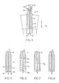
- Figure 2 is a cross sectional view of one type of sample metering valve of the invention with its piston extended.
- Figure 3 is a cross sectional view of the sample metering valve of Figure 2 with the piston retracted so as to isolate the sample.
- Figure 4 is a cross sectional view of another type of sample metering valve for handling slurries or other samples with gas bubbles therein which must be compressed.
- Figures 5 through 8 are views of the sample metering valve of Figure 4 in various states of its operation of drawing sample liquid, compressing any entrained gas, and determining the final, compressed volume.
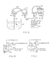
- Figure 9 is a diagram of another type of sample metering valve suitable for sampling slurries.
- Figure 10 is a symbolic diagram of a 6 way valve in a first state which may be used to replace the sample metering valve for certain types of samples.
- Figure 11 is a symbolic diagram of the 6 way valve of Figure 10 in a second state.
- Figure 12 is a diagram of an alternative embodiment of the basic invention where the collection of valves constituting the two manifolds in Figure 1 are replaced in part by multiport rotary valves.
- Referring to Figure 1 there is shown a diagram of the sample preparation system of the invention. The system includes a sample preparation chamber 10 the details of which are given in U.S. patent application "Sample Preparation Chamber With Mixer/Grinder and Sample Aliquot Isolation", serial number 942,198, filed 12/16/86 which is hereby incorporated by reference. For completeness here, a short summary of its structure and operation will be given.
- The sample preparation chamber is capable of being used to prepare many different types of samples for chemical assay, especially by liquid chromatography. The sample preparation chamber is comprised of a sloped
bottom cup 12 which is lightweight, transparent and disposable for holding the sample liquid or solid. The cup threads or otherwise attaches to a cap 14 which serves to keep liquids in by aliquid seal 16 between the cup flange and the mating cap flange. The detachability of the cup allows the cup to be removed and taken to the location of the sample so that a measured amount of sample may be placed therein for solid samples which cannot be pumped as symbolized by theweighing machine 18. Several elements pass through the cap. These elements include a fill/drain pipe 20 which extends to the lowest point 22 in thesloped bottom 24 of the cup and has a diameter which is large enough to pump viscous liquids through without excessive pressure being required. Asecond fill pipe 26 also passes through the cap, but does not extend to the bottom of the cup. In the preferred embodiment, thefill pipe 26 is adjustable such that the height of the bottom of the fill pipe from the bottom of thecup 12 may be either manually adjusted or adjusted by any known mechanism acting under the control of the control system 98. This fill pipe may have a smaller inside diameter than the fill/empty pipe 20, and may be used to pump liquid sample, solvents or diluent into the cup, especially less viscous liquid samples. - There is also a nozzle 28 which extends through the cap 14. This nozzle is used to wash down the side walls of the
cup 12. The nozzle 28 is a propeller like structure in line with the outlet of apipe 29. To use this feature, the user pumps solvent or some other liquid through thepipe 29 connected to the nozzle. The fluid flow causes the propeller or nozzle element to spin. This deflects fluid laterally out toward the side walls of thecup 12 thereby washing down the walls. - The sample container also includes a stirring/grinding
mechanism 30. This mechanism includes amotor 30 driving ashaft 32 which passes through the cap 14. Theshaft 32 is coupled to a propeller 34 or other stirring structure which may or may not be suitable for grinding solid samples. The user may change the structure of the stirrer/grinder propeller 34 to best suit the types of samples the user customarily prepares for assay. For example, high speed homogenizers or ultrasonic probes may be substituted. - A
sample metering valve 36 is also provided for allowing the user to isolate a known volume of sample from the rest of the material in the cup. In the particular embodiment shown in Figure 1, the sample volume is isolated in theportion 38 of the sample metering valve. This known volume may then be released back into thecup 12 after the rest of the sample has been pumped to waste through aneffluent line 20. Thesample metering valve 36 and the mixer/grinder 30 may both be driven either by an electrical motor or a pneumatic drive mechanism. Those skilled in the art will appreciate an adequate drive mechanism for the mixer/grinder 30. The details of the sample metering valve are given in U.S. patent application "Sample Valve For a Sample Preparation System", filed 12/16/86, serial number 942,201 which is hereby incorporated by reference. For completeness here, a short summary of the different types of sample valves will be given. - The sample metering valve is shown in the extended position in Figure 2. This valve is a device which can repeatedly and accurately isolate a known volume of sample from a larger volume of sample. The sample metering valve used in the invention includes an
open end cylinder 13 in which there is positioned apiston 11 having a T shaped sealingend plug 15. Thepiston 11 slides back and forth in thecylinder 13 within the confines of 17, 29 and 27 between an extended position and a retracted position. The T shaped sealingend plug 15 is sized so as to form a sealing plug in theopen end 19 of the cylinder. Acylindrical recess 21 is formed in thepiston 11 up from the sealingplug end 15 and is placed on thepiston 11 such that therecess 21 is exposed to the surrounding medium when thepiston 11 is in the extended position. This causes therecess 21 to fill up with the material of the surrounding medium when thepiston 11 is extended. When thepiston 11 is retracted, the material in therecess 21 is isolated. - No O ring seals are used on the
piston 11 in the valve of the invention. Instead, asoft material 29 is sandwiched at both ends 31 and 33 between two harder retaining rings 17 and 27. Aspring 31 is disposed inside the cylinder concentrically around thepiston 11. Thisspring 31 contacts thering 27 of relatively harder material at the end of the softer material farthest from the sealing plug 14 on thepiston 11. The purpose of thespring 31 is to apply a bias force along the negative y axis to the relatively harder ring to exert pressure on the softer material of the sealingcylinder 29 to cause it to expand against the side wall of thepiston 11 thereby forming a better seal. Because there are no gaps between the relatively harder sealing rings 17 and 27 and the relativelysofter sealing cylinder 29, and because the intersections between therings piston 11 is extended, no dead volume is available to fill with unknown volumes of sample. - Typically, the
piston 11 is driven either by a pneumatic system or by stepper motors (not shown). - Another embodiment of a metering sample valve is a syringe type valve shown in Figures 4 through 8. This valve is especially useful in dealing with slurries with entrained gas bubbles or foam. These bubbles of gas take up volume in an isolated sample which can lead to inaccuracy in predicting the actual volume of liquid which has been isolated in a metering valve. The syringe tube
sample metering valve 11 utilizes acylinder 37 with apiston 41 therein and a separately movable end plug orvalve 39. The end plug 39 is moved to an open position so that the surroundingmedium 51 may enter thecylinder 38. During filling of the valve, thepiston 41 is drawn by apiston drive mechanism 47 to the pistons retracted position to create more volume inside thecylinder 37 thereby lowering the pressure inside the cylinder and causing the it to fill with sample. After the cylinder sample volume is filled, thevalve 39 is closed and thepiston 41 is separately moved down toward thevalve 39 thereby compressing any gas bubbles entrained in or otherwise trapped in the sample volume of thecylinder 37. During this downward movement of thepiston 41, the amount of movement, i.e., the distance thepiston 41 moves toward the valve during the compression stroke, is monitored by a sensor (not shown but part of the piston drive mechanism 47). When the piston has moved far enough to satisfy a user defined criteria, such as spill from thevalve 39 caused by the the compression pressure slightly exceeding the force with which thevalve 39 is held closed by thevalve drive mechanism 43, the total movement of thepiston 41 is determined. This done by direct measurement, interpolation of sensor output data from the sensor or by reading the motor step number in the case of astepper motor drive 47 for thepiston 41. The total volume of liquid in thesyringe valve 11 is calculated by subtracting the volume displaced by the movement of the piston toward thevalve 39 during the compression stroke from the total original volume of sample in the cylinder before the beginning of movement of the piston during the compression stroke. - The sample may then be released by causing the
valve 39 to unseal the cylinder and either letting the sample flow out of thecylinder 37 or by pushing it out by further movement of thepiston 41. With liquid samples, especially very viscous samples, the syringe type embodiment has the added advantage that the process of filling the cylinder sample volume with sample may be speeded up by using the piston to draw up the sample into the cylinder by moving it away from the sealing plug from a position adjacent to the sealing plug at the time the plug is opened. - The preferred embodiment of the sample metering valve for use in slurry and other sample situations where the volume consumed by gas bubbles exists is comprised of three, three way valves coupled to a sample metering pump and a source of pressurization (gas in this example) as shown in Figure 9. A first three way valve A (basically a Y valve) has its
common port 3 coupled to afill pipe 20 in asample chamber 54. The number 1 port of valve A is coupled to the number 1 port of another three way valve B. This connection forms asample chamber 64 between the valve mechanisms of the first and second valves, A and B respectively. Thenumber 2 ports of the two valves A and B are coupled together to form abypass loop 74. Thecommon port 3 of thenumber 2 valve is coupled to thecommon port 3 of a third three way valve C which has one of its ports,port 2, coupled to the sample pump 70 and the other port,port 3, coupled to the source ofpressurized gas 76. - The valves A, B and C are operated to couple the sampling pump 70 to the
fill tube 20 in the chamber. The sample pump is driven so as to suck sample up through thefill tube 20 into the first valve A and out through thesample chamber 64 until enough sample is drawn to completely fill thesample chamber 64 and excess sample is drawn through the valve B intopipe 66 which excess sample is sufficient in volume to compensate for the effects of compression. The first valve A number 1 port is then closed by turning its valve plate 50 to isolate the sample in thesample chamber 64, and the third valve C is operated to couple the pressurized gas atsource pipe 76 into thesample chamber 64 through the B valve so as to compress the gas bubbles in the sample trapped there to a small volume. The second valve B is then operated to trap the compressed sample between the first andsecond valving mechanisms 50 and 51 in valves A and B respectively. This trapped volume may be a known volume or an unknown volume of high reproducibility depending on the application. The sample pump 70 is then operated in the direction so as to empty the rest of thesample 56 not so trapped through thelines container 54 and rinse excess sample away. The solvent is then pumped to waste. Alternatively, the pump 70 may substitute for the compressedgas source 76, or a pressurized sealed head space 22 may substitute as the sample drive mechanism for the pump 70 in the withdrawal ofsample 56 fromvessel 54 either throughloops sample chamber 64 and to pump a known quantity of solvent through the lines and to push the trapped sample into the sample chamber in preparation for the next desired sample preparation step. - Referring again to Figure 1, the rest of the sample preparation system will be described. A key element in the system is the
liquid pump 84. This pump is reversible such that it may pump liquid in either direction though thepipes pump 84 must be capable of delivering repeatedly, very accurate volumes of liquid since it will be used to pump in precise volumes of diluent to dilute the known volume of sample released from the sample metering valve. Typically pumps with inlet and outlet check valve structures are not reproducible enough in the deliveries of known volumes because of the dead volume of liquid which inevitably results from the check valve operation. Any type of pump with an unpredictable or not reproducible dead volume associated with its output valve structure will not be satisfactory. Dead volume is the unknown, variable volume of liquid trapped by the output valve mechanism which will be released the next time the valve opens to thereby destroy the accuracy of the volume delivered by the pump. Any type of pump and valve/flow meter combination which can accurately deliver a user defined volume of diluent will be satisfactory. A positive displacement pump which is accurate to within 1% volumetric accuracy and 1% relative standard deviation in dispensement precision will be adequate. One type of pump which works well is a "swash" pump. This type, as is known by those skilled in the art, uses a tilted rotating shaft inside a cylinder. The walls of the cylinder have input and output ports located on opposite sides at different levels such that the rotation of the shaft opens and closes the ports sequentially. The axial displacement of the shaft within the cylinder causes liquid to be drawn in from one port and pumped out the other port. The direction of pumping may be changed by reversing the direction of rotation of the pumping plate. The rotation of the plate is controlled by a stepper motor or other mechanism which can precisely control the position of the plate to maintain the output port closed when pumping is not occurring. Such pumps are a manufactured by Fluid Metering Inc. and are patented in U.S. patents 3,168,872 and 3,257,953 both of which are hereby incorporated by reference. Other types of pumps such as syringe pumps will also suffice to practice the invention, but in high volume applications, these syringe pumps may not be commercially practicable. - Another important criteria regarding the selection of the pump is that the sealing mechanism be reliable for a large number of cycles without failure.
- The
pump 84 is coupled by acontrol bus 85 to a control circuit/user interface 98 which provides control signals to cause thepump 84 to pump an amount of liquid defined by the control signal in the direction defined by the control signal. The pump drive mechanism may be any type of mechanism such as pneumatic, or stepper motor which can provide the necessary precision of rotor position and accuracy in delivery volume. The details of the control circuit/user interface are not critical to the invention, and those skilled in the art will appreciate that many different type of control mechanisms may be used to control the pumps and valves in the system to do a plurality of different functions and to prepare a plurality of different types of samples for analysis. For example, a programmed digital computer driving stepper motor interface circuits and interface circuits for solenoid operated valves may be used. Further, the control circuit may be dedicated logic, a state machine or a mechanical or analog electronic computer. The interface to the pump and valves may also be via electrically driven pneumatic or hydraulic valves which send pneumatic or hydraulic signals to the pump and valves in the system to cause them to perform the desired functions in the proper sequence. Further, the control circuit 98 may not be a circuit at all in some embodiments, but instead may be a human operator who does all the calculations and operates the valves in accordance with the sequence of steps necessary to process a particular type of sample. - The
pipes valves manifolds pump 84, are coupled by control signals to a control circuit/user interface 98. The control signals are not shown in full detail since to do so would unduly complicate the drawing. All valves may be solenoid operated valves, or they may be pneumatically operated or driven by stepper motors. The manner of driving the valves is not critical to the invention. Regardless of the type of drive mechanism, all valves should be such that they may be opened and closed upon receipt of the proper control signal from whatever control mechanism is being used to control the system. For example, these control signals arrive oncontrol buses 100 and 102 forvalves - The
manifolds valve 102 couples apressure source 104 to themanifold 94. The other valves and facilities in the system are:valve 106 couples thevacuum source 108 to the manifold 94; valve 110 coupleswater supply 112 to the manifold 94;valve 114 couples the manifold to a 6 way injection valve and to thefill pipe 26;valve 118 couples the manifold 94 to the nozzle 28; valve 120 couples manifold 94 to an isolation chamber (not shown) in the processstream sample valve 122; valve 124 couples the manifold 96 to afilter 126 and ananalyzer 128;valve 130 couples manifold 96 to an input port 132 for a first solvent; valve 134 couples the manifold 96 to aninput port 136 for a second type of solvent; valve 138 couples the manifold 96 to aninput part 140 for a third type of solvent; valve 142 couples the manifold 96 to aneffluent pipe 144 which is coupled to the fill/empty pipe 20 through a threeway valve 146. The threeway valve 146 has aninput port 148 which is coupled through afilter 150 to the isolation chamber of the processstream sample valve 122. The threeway valve 146 also has two output ports one of which is the fill/empty pipe 20 and the other of which is theeffluent line 144. A control signal on thecontrol bus 150 controls which of the output ports of thevalve 146 at any particular time is coupled to theinput port 148. Each of the valves coupled to themanifolds - The system described above is capable of preparing in different ways many different types of samples from several different sources for analysis by the
analyzer 128. For example, the system provides the facility to convert solid samples to diluted liquids at a known concentration. This process involves the following steps. For tablet or granular samples or viscous liquids which do not readily flow, thecup 12 is removed from the cap 14 and taken to the location of the sample. A user determined quantity of the sample is placed in the cup. This may be done by using the weighingmachine 18 to weigh the cup before and after placing the sample therein to determine the mass of the sample which has been placed in the cup. The weighingmachine 18 can be used to transmit the weight data directly to the control circuit 98 via thebus 152. The control circuit 98 may then use this information to perform calculations to adjust the dilution factors appropriately, or simply retransmit such information to another device. - The cup is then placed back on the cap 14. If the sample is a tablet, the control circuit 98 turns on the mixer/
grinder 30 to grind the tablet into smaller pieces to speed up the process of dissolving it in diluent. For granulated or viscous samples, this step may be eliminated. - Next, the sample must be dissolved to form a solution of the proper viscosity, composition, and concentration for pumping through the
LC column 128 or other analyzer. Because the control apparatus 98 knows the weight of the sample in the cup from previous steps and has the desired concentration from the user, a calculation may be performed by the control apparatus or by the human operator (hereafter an automated control apparatus will be assumed, although the processes may be performed manually under the control of a human operator who either physically controls the valves and switches driving force to the pump for times calculated by the operator) to determine how much solvent or diluent to pump into thecup 12 to get the desired concentration. The control/user interface system 98 (hereafter the control system) then sends the proper control signals to switch the proper valves to the proper states to pump the selected solvent or solvents into the cup and sends the proper control signals to turn on thepump 84 and cause it to pump in the proper direction to deliver the calculated amount of solvent into thecup 12. For example, if solvent number 1 is to be used, control signals would be generated to openvalve 130 and to open eithervalve 118 orvalve 114 depending upon whether the walls were to washed down or not. The proper control signals to activate thepump 84 would then be generated to cause the pump to pump solvent from the port 132, through the manifold 96 and thepipe 88 through thepump 84 and thepipe 86, through the manifold 94 and out into thecup 12 through either the nozzle 28 or thefill pipe 26. These control signals to the pump are such as to cause the necessary volume of solvent to achieve the desired concentration to be pumped into thecup 12. - After the solvent is pumped in, the mixer/
grinder 30 may be turned on to mix the solvent and the powder or solid chunks to dissolve the solids. Of course with granulated or powder samples the above noted step of turn ing on the mixer/grinder before pumping in the solvent may be eliminated. In such embodiments, the solvent may be pumped in as soon as the cup is attached to the lid, and then the mixer/grinder 30 may be turned on to dissolve the sample. - Once the sample is dissolved, if the proper concentration of solvent is present and the solution is homogeneous, the control system forces a predetermined volume of the diluted sample to be pumped to the LC system. To do this the control system 98
causes valves valve 145 in the effluent line to be closed. Thevalve 146 is caused to couple theportion 160 of the effluent line to theportion 144 of same andpipe 148 is closed off by thevalve 146. The result of all these valve operations is than pressurized gas from thepressure source 104 pressurizes the sample preparation chamber defined by thecup 12 and the cap 14 via themanifold 94 and thefill pipe 26. Theseals 16 prevent the pressurized gas from leaking away. The pressure forces the liquified sample in the chamber to enter theportion 160 of the effluent line and pass through thevalve 146 to theportion 144 of the effluent line. Because thevalve 145 is closed, the sample enters thepipe 162 and passes through the manifold 96 where it passes through the valve 124,pipe 164 andfilter 126 and is forced through theliquid chromatography analyzer 128. - The problem with this approach is that it is not known how much liquid has been pumped. Generally, it is desirable to pump between 4 to 6 times the volume of the connecting tubings (as a minimum) through the system to flush out the lines and to fill the "loop" in the valve in the
LC system 128. It is preferred because of timing considerations to know exactly when the sample loop is filled up so that the timing of examination of the output may be established. - If the proper concentration for the sample was not present after the solvent was pumped in, the sample metering valve may be operated as described above by the control system to take a known volume of sample and isolate it. Then the control system causes the three
way valve 146 tocouple pipe 160 topipe 144 andvalve 145 to open. Then, thevalves effluent line 160 to waste by the pressurized gas. Next, if desired, the walls may be washed down by opening one ofvalves 130, 134 or 138 and thevalves grinder 30, which may a variable speed motor in the preferred embodiment, may be turned on at a high speed during or after the sprinkling process to create turbulence to more thoroughly clean the walls. After the excess sample and solvent are cleaned off the walls, the waste solvent and sample in thecup 12 may be driven to waste by use of thepressurized gas source 104 as defined above. Thereafter, the control system operates the sample metering valve to release the isolated sample back into thecup 12, and operates thepump 84 to pump a calculated amount of solvent into the cup to achieve the user defined concentration for the diluted sample. The manner of doing these operations is as defined above. - Once the desired sample concentration is reached, and the liquid in the cup is homogeneous, the system is ready to have the diluted sample pumped through the LC system. To do this, the pressurized gas method defined above can be used, but the preferred embodiment of getting the liquid sample out of the sample chamber, regardless of whether it was originally two phase liquid/solid, two phase liquid/liquid, solid or extremely viscous is to pump the diluted sample out using the
pump 84. The reason this pumped method is preferred is that the system is less complicated from a timing standpoint. With a known volume system, it is known how many pump strokes are necessary to move liquid from thesample cup 12 to theLC system 128. Thus the time to get the sample to the LC system is known, and the control system can control the LC system based upon this known time. If the pressurized gas method is used, the time it takes the liquid sample to get from the sample cup to the LC system is not known because of the the unknowns of the viscosity of the diluted sample changing from one sample to the next, and any tubing or fitting changes may also alter the timing. To control such a system, there would have to be an interrupt generated to the control processor or control system when theLC system 128 received the required amount of sample and is ready to go. A polled system would also work. These timing considerations, although not terribly complicated, are additional functions the control system must perform. - To pump the sample to the
LC system 128 using thepump 84, thevalves fill pipe 26,manifold 94,pipe 86,pipe 88 andmanifold 96 andpipe 164 as the pathway. This provides better control of the volume of sample delivery to the LC system so that the control of theLC analysis system 128 needs no interrupt or polling to indicate when the sample has arrived. To perform the above steps however requires that the amount of solvent/diluent pumped into the sample preparation chamber be such as to bring the liquid level of the diluted sample at the final concentration to a level above the end of thefill pipe 26. To avoid such complications, it is preferred to put the end 166 of thefill pipe 26 close to thebottom 168 of the sample preparation chamber. This eliminates the need for tradeoffs regarding the volume of the isolation chamber and the volumes of solvent/diluent to pump in to make sure that at all volumes of samples, the final liquid level after dilution will be above the level of the end 166 of thefill pipe 26. In the preferred embodiment, the level of the bottom 166 of thefill pipe 26 may be manually or automatically adjusted to account for such variations. This provides the extra facility of being able to keep the bottom 166 of the fill pipe off the bottom for samples which have sediment or solid material therein which could plug thefill pipe 26 if they were sucked up into the fill pipe. - The sample preparation process where clean, homogeneous samples are to be analyzed, there is no need for the step of homogenization. In such a situation, a 6 way valve may be used to introduce the sample to the
cup 12. This valve may be used to isolate a known volume of sample in a loop betweenvalve ports port 180 is connected to the sample vat and is also connected toport 182.Port 182 is always coupled toport 184 by an internal or external passageway regardless of the state of the valve. It is this passageway which will be used as the isolation chamber in place of the sample isolation chamber in the sample metering valve. Theport 186 is coupled to theport 184 in this first state, and is also coupled to the manifold 94 through thevalve 114. While the 6 way valve is in the state shown in Figure 10, the control system 98 opens thevalves port 186. This draws sample up from the sample vat and fills the loop betweenports ports ports Port 186 could then be simply connected to any waste receptacle. - The control system then switches the 6 way valve to the state shown in Figure 11. In this state, the
ports ports port 190 is coupled to the manifold 94 by an additional solenoid or pneumatically operatedvalve 192, and theport 188 is coupled to thecup 12 via thefill pipe 26. When the 6 way valve is operated by the control system to put it in the state shown in Figure 11, the sample that filled the passageway between theports valves solvent valves 130 or 134 or 138 and operates thepump 84 to pump a known volume of solvent into thecup 12. The known volume of solvent is computed based upon the known volume of the passageway between theports grinder 30. Thereafter, the diluted sample may be transferred to theanalyzer 128 in any of the manners described above. In alternative embodiments, theports ports ports fill pipe 26 and to the manifold 94, and thevalve 192 is not needed. - The system according to the teachings of the invention is capable of isolating known volumes of samples from a process stream and preparing same for the analyzer. The
valve 122 in Figure 1 is used for this purpose. Control system 98 implements the process by causing thevalve 122 to extract and isolate a known volume of sample flowing inprocess stream 192. Thevalve 122 is preferably an ISOLOKT valve series M$ manufactured by Bristol Engineering of Yorkville, Illinois or equivalent. This valve is similar in operation to the valve shown in Figures 2 and 3 except that the there are additional ports in the cylinder of the valve coupled to thepipes chamber 21 in Figures 2 and 3 is in a position such that pressurized gas or liquid in thepipe 194 will sweep the isolation chamber clear of sample and drive it intopipe 196 or vice versa. - To sample a process stream then, the
valve 122 is operated by the control system 98 to isolate an aliquot of sample from theprocess stream 192. Then, thevalves valve 145 is closed, and the threeway valve 146 is operated to couple thepipe 148 to thepipe 160. Thepump 84 is then operated to draw a calculated amount of solvent from the solvent source and drive it through thepipe 194, theISOLOK valve 122 and thepipe 196 to sweep the isolated sample out of the isolation chamber and into thecup 12 through thevalve 146 and theeffluent line 160. The amount of solvent drawn by thepump 84 is calculated from the desired final concentration and the known volume from the ISOLOK valve. Although the exact volume from the ISOLOK valve will not be known to the same precision as would the volume in the isolation chamber of the sample metering valve because of unknown dead volumes in the sealing rings, the precision is good enough for most applications. - Next, the mixer/
grinder 30 is activated to homogenize the sample, and the liquid is then driven to theanalyzer 128 for analysis in the manner described above. - Slurry and other types of samples sometimes have gas bubbles entrained in the liquids. Gas bubbles may be at least partially drawn off before sample aliquot isolation in the system of Figure 1 by the application of vacuum to the sample preparation chamber before operating the sample metering valve. The lower than atmospheric pressure causes outgassing of the gas entrained in the slurry or in foam bubbles on top of the liquid. Application of the vacuum is performed by the control system 98 by opening the
valves cup 12 in any of the processes described above. After the gases are drawn completely or substantially off, thesample metering valve 36 is operated to draw in an aliquot of slurry and to compress it as described above. After compression, a known volume of the compressed slurry is isolated, and the remaining slurry is transferred to waste as described above. The walls of the sample preparation chamber may also be washed down as described above if desired. Finally, thesample metering valve 36 is operated to release the isolated sample aliquot, and a known volume of solvent is pumped in as described earlier to arrive at the final concentration (serial dilution is possible in this process as it is in any of the processes described herein). The mixer/grinder 30 is then turned on by the control system 98, and the required amount of the diluted sample is transferred to theanalyzer 128 as described above. - The
water supply 112 may be used to flush out all the pipes in the system by properly operating the valves, but its principal use is in flushing out the sample preparation chamber. - Referring to Figure 12 there is shown a diagram of another embodiment of the sample preparation system of the invention. In this embodiment, the sample valve is comprised of the three way valves V1, V2 and V3 which operate in the manner described with respect to Figure 9. Further, the
manifolds rotary valves 1 and 2. All the valves are controlled by a control system (not shown) which causes the valves to operated in the proper sequence as described below. To take a sample in the system of Figure 12, thecup 12 is filled with sample, and valves V1, V2 and V3 are operated to gate thedrain line 200 to wasteline 202 through the sample loop and the dead volume. The sample is driven to waste by pressurizing the cup via proper operation of V7 to pressurize thegas reservoir 204 with gas and then to use the gas reservoir pressure to pressurize the cup through the valves V7, V6 and thepressure regulator 206. - After the sample loop has been filled, valves V1 and V2 are operated to isolate the sample loop, and V7, V4 and rotary valve 1 are operated to pressurize
lines drain line 200 to thewaste line 202 and the cup is again pressurized using thegas reservoir 204, valves V7 and V6,pressure regulator 206 and thelines 214 and 216. This forces all the sample out of the cup. - The cup is then rinsed by operating
rotary valves 1 and 2 and valves V4 and V5 and pump 220 to pump solvent fromreservoir 222 into thesprayer reservoir 224. The sprayer reservoir is then pressurized by operating valves V7, V4, and V5 and rotary valve 1 so that pressurized gas is directed fromgas reservoir 204 into the sprayer reservoir. The cup is then washed by operating valve V5 so as to direct the solvent in thesprayer reservoir 224 through therotary sprayers 226 vialine 228. The rotary sprayer directs the pressurized solvent stream around inside the cup to wash down all the internal structures by solvent impact. The cup is then emptied of solvent by pressurizing the cup in the manner described above and operating valves V!, V2 and V3 so that the solvent is directed throughpipe 230 and the dead volume out through thewaste pipe 202. - The fixed volume of sample trapped in the sample loop is then driven back into the cup by operating the
pump 220 androtary valves 1 and 2 to suck a desired diluent/solvent from a reservoir 222 (or other solvents in other reservoirs coupled torotary valve 2 could be used) and pump it throughpipe 232, valve V4,pipes drain pipe 200. Thepump 220 is driven to pump a known volume of the selected solvent into the cup thereby pushing the known volume of sample in front of the pumped solvent into the cup along with a known amount of solvent.Pulse dampeners - Having reduced the sample aliquot to the proper concentration, the system is now ready to be pumped through the chromatography system. This is done by operating valves V1, V2, V3 and V4 and
rotary valves 1 and 2 such that a path is established from thedrain pipe 200 through thepump 220 and outpipe 244 to the chromatography system for assay. If it is desired to sample from a higher layer, thepipe 246 may be used by properly operating the valves in the system to usepipe 246 as the input path to thepump 220. The pipes in the system which still have sample in them and the cup may be purged with solvent in a manner which will be apparent to those skilled in the art from the above discussion. - Another manner of using the system of Figure 12 is to put a liquid sample containing a chemical of interest in solution in the cup. The pump and valves may then be operated to pump a known volume of the sample through the liquid chromatography column to concentrate the chemical of interest on the active agent which coats the packing material of the column.
- Although the invention has been described in terms of the preferred and alternative embodiments detailed herein, other alternative embodiments may be apparent to those skilled in the art. All such alternative embodiments which appropriate the spirit of the invention are intended to be included within the scope of the claims appended hereto.
Claims (12)
placing a non-homogeneous two phase sample in a sample preparation chamber (12);
homogenizing the sample with a stirrer (30,34);
isolating a known volume of the sample from the balance of the sample in said sample preparation chamber;
flushing the non-isolated volume of sample to waste;
releasing the isolated sample volume back into said sample preparation chamber;
placing a user defined amount of a user defined diluent in said sample preparation chamber;
homogenizing the sample;
repeating the above steps as required until a user defined sample concentration has been reached; and
delivering a predetermined volume of said diluted sample to said assay device.
automatically rendering the sample suitable for dilution in a solvent;
diluting the sample to a user defined concentration; and
homogenizing the sample;
delivering the diluted sample to a chemical assay system.
placing a known amount of solid sample in a sample preparation chamber (12) having a grinding and stirring mechanism (30,34) therein;
grinding the sample until it is in pieces small enough to be dissolved in a user defined solvent;
placing a known quantity of solvent in the sample preparation chamber (12);
mixing the sample with the solvent until the mixture is homogeneous;
repeating the above steps if necessary until a user defined concentration for the sample is reached;
delivering the diluted sample to said assay system.
placing an aliquot of said sample in a sealed sample preparation chamber (12);
applying subatmospheric pressure to said sample preparation chamber to draw off the gas bubbles;
isolating a known volume of the sample;
removing the rest of the sample in the sample preparation chamber;
adding a user defined amount of diluent to the sample preparation chamber and releasing the isolated volume of sample into the sample preparation chamber;
homogenizing the sample and diluent;
repeating the above steps until a user defined concentration is reached;
delivering the diluted sample to an assay system.
placing said sample in a sample preparation chamber;
drawing some of said sample into a sample metering valve and isolating the portion so drawn from the balance of the sample in the sample preparation chamber;
compressing the portion of said sample drawn into said sample metering valve;
isolating a known volume of the compressed sample drawn into said sample metering valve;
removing the rest of the sample from the system;
releasing the isolated sample and adding a user defined amount of diluent to said sample in said sample preparation chamber;
homogenizing the sample and diluent;
repeating the above steps as necessary until a user defined sample concentration is reached;
delivering the diluted sample to an assay system.
placing an aliquot of sample in a sample preparation chamber;
isolating a known volume of said sample;
flushing the non-isolated volume of sample to waste;
spraying a user defined solvent against the walls of said sample preparation chamber;
flushing the solvent so sprayed to waste;
releasing the isolated volume of sample back into said sample preparation chamber and adding a user defined amount of diluent;
homogenizing the mixture of sample and diluent;
repeating the above defined steps until a user defined concentration is reached; and
delivering the diluted sample to the assay system.
operating a sampling valve so as to extract a known volume of sample from a process stream and isolate it from the process steam;
driving the isolated sample aliquot out of the sampling valve and into a sample preparation chamber;
placing a user defined amount of diluent in said sample preparation chamber;
homogenizing the sample and diluent in said sample preparation chamber; and
delivering the diluted sample to said assay system.
filling a passageway of a known volume in a 6 way valve where said passageway is common to at least two switching states of said six way valve, said filling occurring while said 6 way valve is in one said two states;
switching said 6 way valve to the other of the two states;
driving the sample so trapped in said common passageway into a sample preparation chamber;
placing a user defined amount of diluent in said sample preparation chamber;
homogenizing said sample and diluent;
delivering the diluted sample to an assay system if a user defined concentration level has been reached;
if a user defined concentration has not been reached, isolating a known volume of the diluted sample and flushing the rest of the sample to waste;
adding a user defined amount of diluent to said sample preparation chamber and homogenizing sample and diluent;
repeating the above steps as necessary until a user defined concentration is reached;
delivering the diluted sample to said assay system.
Applications Claiming Priority (4)
| Application Number | Priority Date | Filing Date | Title |
|---|---|---|---|
| CH3455/86 | 1986-08-28 | ||
| CH345586 | 1986-08-28 | ||
| US06/942,353 US4859605A (en) | 1986-12-16 | 1986-12-16 | Process for preparation of samples for analysis |
| US942353 | 1986-12-16 |
Publications (2)
| Publication Number | Publication Date |
|---|---|
| EP0259257A2 true EP0259257A2 (en) | 1988-03-09 |
| EP0259257A3 EP0259257A3 (en) | 1989-02-15 |
Family
ID=25693045
Family Applications (1)
| Application Number | Title | Priority Date | Filing Date |
|---|---|---|---|
| EP87810473A Withdrawn EP0259257A3 (en) | 1986-08-28 | 1987-08-24 | Process for preparation of samples for analysis |
Country Status (1)
| Country | Link |
|---|---|
| EP (1) | EP0259257A3 (en) |
Cited By (4)
| Publication number | Priority date | Publication date | Assignee | Title |
|---|---|---|---|---|
| EP0259259A2 (en) * | 1986-08-28 | 1988-03-09 | Ciba-Geigy Ag | System for preparation of samples for analysis |
| EP0433462A1 (en) * | 1989-06-16 | 1991-06-26 | MITSUI TOATSU CHEMICALS, Inc. | Automatic analyzing method and device |
| CN102692519A (en) * | 2011-03-24 | 2012-09-26 | 江苏江分电分析仪器有限公司 | Multipath liquid sampler |
| US11774415B2 (en) | 2020-03-26 | 2023-10-03 | Waters Technologies Corporation | Metering pump for liquid chromatography |
Citations (4)
| Publication number | Priority date | Publication date | Assignee | Title |
|---|---|---|---|---|
| US3223485A (en) * | 1962-09-07 | 1965-12-14 | Technicon Instr | Apparatus for treatment of solids for analysis |
| EP0089937A1 (en) * | 1982-03-22 | 1983-09-28 | Erik Öhlin | Apparatus and method for serial dilution of liquid samples |
| FR2579749A1 (en) * | 1985-03-28 | 1986-10-03 | Serg Gts | Automatic device for diluting by continuous sampling of liquid samples to be diluted and by batch dilution |
| EP0259258A2 (en) * | 1986-08-28 | 1988-03-09 | Ciba-Geigy Ag | Sample preparation chamber with mixer/grinder and sample aliquot isolation |
-
1987
- 1987-08-24 EP EP87810473A patent/EP0259257A3/en not_active Withdrawn
Patent Citations (4)
| Publication number | Priority date | Publication date | Assignee | Title |
|---|---|---|---|---|
| US3223485A (en) * | 1962-09-07 | 1965-12-14 | Technicon Instr | Apparatus for treatment of solids for analysis |
| EP0089937A1 (en) * | 1982-03-22 | 1983-09-28 | Erik Öhlin | Apparatus and method for serial dilution of liquid samples |
| FR2579749A1 (en) * | 1985-03-28 | 1986-10-03 | Serg Gts | Automatic device for diluting by continuous sampling of liquid samples to be diluted and by batch dilution |
| EP0259258A2 (en) * | 1986-08-28 | 1988-03-09 | Ciba-Geigy Ag | Sample preparation chamber with mixer/grinder and sample aliquot isolation |
Cited By (8)
| Publication number | Priority date | Publication date | Assignee | Title |
|---|---|---|---|---|
| EP0259259A2 (en) * | 1986-08-28 | 1988-03-09 | Ciba-Geigy Ag | System for preparation of samples for analysis |
| EP0259259A3 (en) * | 1986-08-28 | 1989-05-17 | Ciba-Geigy Ag | System for preparation of samples for analysis |
| EP0433462A1 (en) * | 1989-06-16 | 1991-06-26 | MITSUI TOATSU CHEMICALS, Inc. | Automatic analyzing method and device |
| EP0433462A4 (en) * | 1989-06-16 | 1992-05-06 | Mitsui Toatsu Chemicals, Inc. | Automatic analyzing method and device |
| US5186895A (en) * | 1989-06-16 | 1993-02-16 | Mitsui Toatsu Chemicals, Incorporated | Method and apparatus for automatic analysis of fluid composition involving a time-dependent variation thereof |
| CN102692519A (en) * | 2011-03-24 | 2012-09-26 | 江苏江分电分析仪器有限公司 | Multipath liquid sampler |
| CN102692519B (en) * | 2011-03-24 | 2015-04-15 | 江苏江分电分析仪器有限公司 | Multipath liquid sampler |
| US11774415B2 (en) | 2020-03-26 | 2023-10-03 | Waters Technologies Corporation | Metering pump for liquid chromatography |
Also Published As
| Publication number | Publication date |
|---|---|
| EP0259257A3 (en) | 1989-02-15 |
Similar Documents
| Publication | Publication Date | Title |
|---|---|---|
| US4980130A (en) | System for preparation of samples for analysis | |
| KR101322543B1 (en) | High Speed Sample Supply Device | |
| USRE26055E (en) | Automatic sample handling apparatus | |
| US4900683A (en) | Process for preparation of samples for analysis | |
| JP5213269B2 (en) | Device for aspirating and dispensing liquids in automated analyzers | |
| US7939017B2 (en) | Automated fluid handling system and method | |
| US6382035B1 (en) | Multi-valving sample injection apparatus | |
| US4859605A (en) | Process for preparation of samples for analysis | |
| US4729876A (en) | Blood analysis system | |
| US3012863A (en) | Apparatus for the preparation of laboratory test samples | |
| US4470316A (en) | Apparatus and method for withdrawing fluid from a source of fluid such as a pipeline | |
| EP0259259A2 (en) | System for preparation of samples for analysis | |
| EP0259257A2 (en) | Process for preparation of samples for analysis | |
| US4894345A (en) | Process for preparation of samples for analysis | |
| US3401591A (en) | Analytical cuvette and supply system wherein the cuvette inlet and outlet are located on the bottom of the cuvette | |
| US3193148A (en) | Sample handling apparatus | |
| US4792434A (en) | Sample preparation chamber with mixer/grinder and sample aliquot isolation | |
| US4925628A (en) | Sample preparation chamber with mixer/grinder and sample aliquot isolation | |
| US3496970A (en) | Apparatus for the preparation of liquid mixtures | |
| JPS6367543A (en) | Preparation of sample for analysis | |
| EP0259258A2 (en) | Sample preparation chamber with mixer/grinder and sample aliquot isolation | |
| US20020051406A1 (en) | Method and apparatus for preparing slurry from starting materials | |
| JP3069599B2 (en) | Preparation method of multi-component compound solution | |
| JPH03170046A (en) | Method for stirring specimen liquid for chemical analysis | |
| GB2088332A (en) | Fluid sampling apparatus |
Legal Events
| Date | Code | Title | Description |
|---|---|---|---|
| PUAI | Public reference made under article 153(3) epc to a published international application that has entered the european phase |
Free format text: ORIGINAL CODE: 0009012 |
|
| AK | Designated contracting states |
Kind code of ref document: A2 Designated state(s): BE CH DE FR GB LI NL |
|
| PUAL | Search report despatched |
Free format text: ORIGINAL CODE: 0009013 |
|
| 17P | Request for examination filed |
Effective date: 19870826 |
|
| AK | Designated contracting states |
Kind code of ref document: A3 Designated state(s): BE CH DE FR GB LI NL |
|
| STAA | Information on the status of an ep patent application or granted ep patent |
Free format text: STATUS: THE APPLICATION IS DEEMED TO BE WITHDRAWN |
|
| 18D | Application deemed to be withdrawn |
Effective date: 19890816 |
|
| RIN1 | Information on inventor provided before grant (corrected) |
Inventor name: METZGER, ANDRE, DR. Inventor name: NOHL, ANDRE J. Inventor name: GRIMM, PETER, DR. Inventor name: NAU, VANCE J. |