EP0259131B1 - A castor - Google Patents
A castor Download PDFInfo
- Publication number
- EP0259131B1 EP0259131B1 EP87307682A EP87307682A EP0259131B1 EP 0259131 B1 EP0259131 B1 EP 0259131B1 EP 87307682 A EP87307682 A EP 87307682A EP 87307682 A EP87307682 A EP 87307682A EP 0259131 B1 EP0259131 B1 EP 0259131B1
- Authority
- EP
- European Patent Office
- Prior art keywords
- leaf spring
- fork
- pedal
- abutment
- wheel
- Prior art date
- Legal status (The legal status is an assumption and is not a legal conclusion. Google has not performed a legal analysis and makes no representation as to the accuracy of the status listed.)
- Expired
Links
- 235000004443 Ricinus communis Nutrition 0.000 title claims abstract description 33
- 230000009471 action Effects 0.000 claims description 10
- 230000000994 depressogenic effect Effects 0.000 claims description 4
- 210000002105 tongue Anatomy 0.000 description 8
- 230000004048 modification Effects 0.000 description 3
- 238000012986 modification Methods 0.000 description 3
- 230000000295 complement effect Effects 0.000 description 2
- 239000002184 metal Substances 0.000 description 2
- 240000000528 Ricinus communis Species 0.000 description 1
- 229910000639 Spring steel Inorganic materials 0.000 description 1
- 230000003993 interaction Effects 0.000 description 1
- 230000007246 mechanism Effects 0.000 description 1
- 238000005096 rolling process Methods 0.000 description 1
Images


Classifications
-
- B—PERFORMING OPERATIONS; TRANSPORTING
- B60—VEHICLES IN GENERAL
- B60B—VEHICLE WHEELS; CASTORS; AXLES FOR WHEELS OR CASTORS; INCREASING WHEEL ADHESION
- B60B33/00—Castors in general; Anti-clogging castors
- B60B33/02—Castors in general; Anti-clogging castors with disengageable swivel action, i.e. comprising a swivel locking mechanism
- B60B33/021—Castors in general; Anti-clogging castors with disengageable swivel action, i.e. comprising a swivel locking mechanism combined with braking of castor wheel
Definitions
- This invention relates to a castor comprising a wheel which is journalled on an axle in a fork which is arranged for swivelling movement about an axis which is normal to the axis of the axle and which is provided with a pedal operable brake for the wheel, the pedal operable brake being carried by the fork and being operable to put a braking element into braking engagement with the circumferential periphery of the wheel when it is applied.
- GB-A-1231381 and DE-A-1918357 disclose examples of such castors provided with a releasable latching arrangement operable to latch the brake applied to the wheel, the latching arrangement comprising a leaf spring which is stressed by movement of the pedal to apply the brake and which urges the pedal to release the brake, the leaf spring extending above the wheel substantially parallel to the path the wheel traces as it rolls and being releasably held by interengagement of a strut portion carried by the leaf spring with an abutment carried by the fork until released by dislodgement of the strut portion to free the pedal and release the brake.
- the releasable latching arrangement is vulnerable to accidental release as the abutment surface engaged by the end of the strut element when the brake is applied is part of a flat surface.
- An object of this invention is to provide a castor with improved releasable latching means.
- a castor comprising a wheel which is journalled on an axle in a fork which is arranged for swivelling movement about an axis which is normal to the axis of the axle, the fork carrying a pedal operable brake for the wheel which is operable to put a braking element into braking engagement with the circumferential periphery of the wheel when it is applied,
- the pedal operable brake comprising a pedal and including a releasable latching arrangement comprising a leaf spring which extends above the wheel substantially parallel to the path the wheel traces as it rolls, which interacts with the pedal and the fork so that it is flexed from its natural flat relaxed condition when the pedal is depressed to apply the brake, and which is releasably held so flexed by interengagement of a strut portion carried by the leaf spring with an abutment carried by the fork to hold the leaf spring flexed from its natural relaxed condition and the brake applied until the strut portion is dislodged
- the braking element is a sprag formed by a respective tongue which is integral with the leaf spring and which depends from the leaf spring towards the wheel.
- the sprag may be one of an opposed pair of such sprags which converge towards the wheel for braking rotation of the wheel in either direction.
- the leaf spring has a protuberance which is adapted to engage an aligned one of a circumferential array of corresponding recesses formed in a hub assembly upon which the fork is journalled for swivelling movement about the axis which is normal to the axis of the wheel axle, the protuberance being spaced from the recesses in the hub assembly when the leaf spring is in its natural flat relaxed condition and being urged in a direction which is substantially parallel to the axis of the hub assembly into engagement with the aligned one of the recesses in the hub assembly by the action of deforming the leaf spring to apply the brake, so that the fork is locked against swivelling movement about the axis that is normal to the axis of the wheel axle when the brake is applied.
- the leaf spring may be forked at an end remote from the pedal, the forked end forming two spaced integral prong portions which engage the fork.
- the protuberance may be formed in an integral projecting portion of the leaf spring which projects between the two prongs.
- the leaf spring may react against the fork at an end remote from the pedal, the protuberance being formed in the leaf spring between said end and the pedal.
- the protuberance is one of a pair of such protuberances which are formed in the leaf spring symmetrically on either side of the longitudinal axis of the leaf spring.
- the part of the leaf spring that reacts against the fork at said end and the two protuberances may be circumferentially spaced around an annular portion of the leaf spring through which the axis of the hub assembly passes.
- the abutment is formed in a release lever which is pivotally mounted on the fork and which is urged into abutment with the fork by the action of the stressed leaf spring acting through the strut element that is engaged with the abutment, the arrangement being such that the release level can be pivoted relative to the fork to dislodge the strut element from engagement with the abutment and thereby to release the stressed leaf spring for return movement to its natural flat condition.
- the release level is a secondary pedal.
- the release lever is pivotally mounted on a pivot carried by a side portion of the fork and is urged into abutment with a surface on the bridge piece of the fork by the action of the stressed leaf spring acting through the strut element that is engaged with the abutment, the pivot being engaged within a corresponding recess which is formed in the release lever so that it is open on one side, the arrangement being such that the pivot is disengaged from the corresponding recess by pivotal movement of the release lever about said surface of the fork whereby to allow the strut element to be displaced from engagement with the abutment and thereby to release the stressed leaf spring for return movement to its natural flat relaxed condition, the release lever being resorted to its normal position in abutment with said surface and with the pivot engaged within the corresponding open sided recess due to the action of the leaf spring as it returns to its normal flat relaxed condition.
- the release lever is hinged to the bridge piece of the fork by the engagement of hinge elements which project from the release lever through
- Figures 1 to 8 of the drawings show a castor comprising a wheel 10 which is journalled on an axle 11 in a fork 12.
- the fork 12 is an inverted U comprising two triangular side portions depending from either side of a connecting body piece.
- the latter which is referred to from now on as the bridge, is formed with an aperture which receives a hub assembly 13.
- the hub assembly 13 includes a double rolling bearing (see Figure 2) by which the fork 12 is arranged for swivelling movement about the axis of the hub assembly 13 which is normal to but laterally offset from the axis of the axle 11.
- the underside of the hub assembly 13 is formed with a circumferential array of recesses 14 (see Figure 3).
- a leaf spring 15 extends between the wheel 10 and the underside of the bridge of the fork 12 in a direction which is substantially parallel to the path the wheel 10 traces as it rolls. A major part of the leaf spring 15 is flat in its normal relaxed condition.
- Two legs 16 depend from the leaf spring 15, one on either side. Each leg 16 is journalled on a respective pivot peg 17 which projects from the inner face of a respective one of the side portions of the fork 12 towards the other side portion of the fork 12 (see Figure 5).
- Figure 3 shows that the end of the leaf spring 15 that is nearer to the hub assembly 13 is forked to form two spaced prongs 18, one on either side of the lower portion of the hub assembly 13 that projects below the bridge of the fork 12.
- Each prong 18 has an upstanding angled end piece (see Figure 2) which engages the underside of the bridge of the fork 12.
- the leaf spring 15 also has an integral central portion 19 which projects between the two prongs 18.
- the central portion 19 is cranked to form a dog leg, the toe end of which is below the prongs 18.
- Two upwardly-projecting protuberances 20 are formed in the central portion 19 at substantially the same radial distance from the axis of the hub assembly 13 as the circumferential array of recesses 14, and are spaced apart angularly by substantially the same arc as two of the recesses 14 which are separated, conveniently by five other of the recesses 14.
- Each protuberance 20 is sized and shaped to seat neatly in a respective one of the recesses 14.
- Two tongues 22 and 23, which are integral with the leaf spring 15, are formed by cut outs in the leaf spring 15, between the legs 16 and the flange 21.
- the tongues 22 and 23 depend from the remainder of the leaf spring 15, converge towards one another, each being in the form of a dog leg, and serve as sprag brakes which are operable to be urged into engagement with the circumferential periphery of the wheel 10 whereby to retard rotation of the wheel 10 in either direction.
- a sheet metal pedal 24 comprises a flat main portion 25 and an integral flange 26 which depends from the sides and one end of the main portion 25 to form a U in plan as seen in Figure 3.
- An adjustment screw 27 is captive in the portion of the flange 26 at the end of the main portion 25, and has its threaded stem extending through an aperture in the flange 21 into engagement with a nut 28 which is clipped to the flange 21.
- the main portion 25 extends over the leaf spring 15 to a location between the legs 16 and the tongues 22 and 23.
- the width of the main portion 25 exceeds the width of the leaf spring 15 and of the tread of the wheel 10 so that the portions of the flange 26 that depend from the sides of the main portion 25 extend on either side of both of the leaf spring 15 and part of the wheel 10 (see Figures 2 and 6).
- a sheet metal release lever 29 which, like the fork 12, has an inverted U-shape (see Figure 7), extends over the pedal 24 at the end of the latter that is nearer to the hub assembly 13, the side portions of the lever 29 extending one on either side of the pedal 24 and towards the axis of the hub assembly 13 below the latter.
- Each side portion of the lever 29 has a T-shaped recess 31 formed in it, the two arms of the T-shaped recess 31 being at the bottom of the recess 31 and having arcuate ends.
- the arcuate end of the arm of each T-shaped recess 31 that is nearer to the hub assembly 13 receives the pivot pin 17 that the respective leg 16 of the leaf spring 15 is journalled upon.
- the medial portion of the release lever 29 rests on top of the pedal 24. It has a lateral fold 32 between its ends, the fold 32 forming an upstanding ridge in its upper surface and a complementary trough in its underside, the ridge and trough extending from side to side of the medial portion.
- the part of the medial portion between the fold 32 and the hub assembly 13 has a top hat section, the raised central portion 33 being in abutment with the adjacent edge of the bridge of the fork 12.
- the spaced lower flat side portions 34 of the top hat section portion project into the gap between the wheel 10 and the bridge of the fork 12 with a clearance between them and the bridge (see Figure 8).
- the edge of the main portion 25 of the pedal 24 at the end which is not flanged is caused to slide along the underside of the two side portions 34 of the release lever 29, away from the fork 12, until it is snapped into the trough formed by the underside of the fold 32, as shown in Figure 8.
- the flat main portion 25 of the pedal 24 serves as a strut so that, when engaged with the spaced abutments formed by the portions of the fold 34 that flank the raised central portion 33, it holds the leaf spring 15 bowed, as shown in Figure 6.
- the operator puts his foot on the end of the release lever 29 that is further from the fork 12 so that the release lever 29 is pivotted about the end surface of the fork bridge with which it is in abutment.
- the pivot pins 17 are disengaged from the respective arcuate ends of the arms of the T-shaped recesses 31 with which they were engaged as shown in Figures 2 and 6.
- Engagement of the edge of the trough remote from the top hat section portion of the release lever 29 with the flat main portion 25 of the pedal 24 displaces the pedal 24 from the trough.
- the leaf spring 15 is released to return to its normal flat condition as shown in Figure 2 to which it is urged in reaction to the engagement of the prongs 18 against the underside of the bridge.
- the relative positioning of the pedal 24 and the release lever 29 can be adjusted by operation of the adjustment nut and screw mechanism 27 and 28.
- Figures 9 to 11 show a modified form of the castor shown in Figures 1 to 8.
- Parts of the castor shown in Figures 9 to 11, which are similar to corresponding parts of the castor shown in Figures 1 to 8, are identified by the same reference numeral as is used in Figures 1 to 8.
- the modifications are to the part of the leaf spring 35 that is in the region of the hub assembly 13, to the release lever 39 and to the pivoted association of the release lever 39 with the bridge of the fork 42.
- Figure 10 shows the part of the leaf spring 35 that is in the region of the hub assembly 13 is annular, having a central aperture through which the axis of the hub assembly 13 passes.
- the annular portion of the leaf spring 35 is symmetrical about the longitudinal axis of the leaf spring 35 which intersects the axis of the hub assembly 13. It replaces the two spaced prongs 18 and the integral central portion 19 of the leaf spring 15 shown in Figures 1 - 8.
- the annular portion of the leaf spring 35 is deformed by pressing at three circumferentially spaced locations to form three upwardly projecting protuberances 38, 40A and 40B.
- the protuberance 38 is located centrally at the end of the leaf spring 35 remote from the pedal 24. It extends below and projects radially outwardly beyond the adjacent rim portion of the bridge of the fork 42 which it engages, thereby serving the same functions as the upstanding angled end pieces of the prongs 18 of the castor shown in Figures 1 - 8.
- the protuberances 40A and 40B which are on diametrically opposite sides of the annular portion of the leaf springs 35, are intended to cooperate with the circumferential array of recesses 14 in basically the same way as do the protuberances 20 of the castor shown in Figures 1 - 8.
- Figures 9 and 11 shows the release lever 39 is hinged to the bridge of the fork 42 instead of being interengaged with the pivot pins 17 and pivoted about the adjacent edge of that bridge as in the castor shown in Figures 1 - 8.
- the release lever 39 which, like the release lever 29, has an inverted U-shape and extends over the pedal 24, has two integral hinge elements 44 which project from it at its end adjacent the fork 42.
- Each hinge element 44 is stepped, comprising a root portion 44A which extends from the medial portion of the major U-shaped portion of the release lever 39 below the adjacent rim portion of the bridge of the fork 42, an intermediate portion 44B which extends with clearance up through a respective aperture 45 in the bridge of the fork 42, and an end portion 44C which extends towards the hub assembly 13 above the bridge of the fork 42.
- the depth of each aperture 45 is sufficiently less than the height of the respective intermediate hinge element portion 44B to allow a limited amount of angular movement of the release lever 29 relative to the fork 42 about the hinge between them.
- the medial portion of the release lever 39 has a lateral fold 46 between its ends, the fold 46 forming an upstanding ridge in its upper surface and a complementary trough in its underside, the ridge and the trough extending from side to side of the medial portion.
- the leaf spring 35 In the brake released condition shown in Figure 9, the leaf spring 35 is in its flat relaxed state, the sprag brake tongues 22 and 23 are displaced from the wheel rim and the protuberances 40A and 40B are displaced from the aligned recesses 14 formed in the hub assembly 13.
- the leaf spring 35 reacts against the rim portion 43 of the bridge of the fork 42 to hold the pedal 24 in its brake released location.
- the release lever 39 rests on the pedal 24 at the end of the latter that is adjacent to the hub assembly 13, the medial portion of the release lever 39 and the flat main portion 25 of the pedal 24 diverging away from that end and forming a tapered space between them.
- the angle between the end portion 44C and the intermediate portion 44B of each of the hinge elements 44 rests on the step formed by the top of the bridge of the fork 42 and the inner surface of the respective aperture 45.
- the medial portion of the lever 39 is at an angle to the bridge of the fork 42 sloping upwardly from the root portions 44A of the hinge elements 44 to pass close to, or touch the edge of the bridge of the fork 42.
- edge of the main portion 25 of the pedal 24 at the end which is not flanged is caused to slide along the underside of the medial portion of the release lever 39, away from the fork 42, until it is snapped into the trough formed by the underside of the fold 46, in substantially the same way as is shown in Figure 6 for engagement of the pedal in the fold 42 of the release lever 29.
- pivot pins 17 are difficult and costly to make. It has been proposed that split, hardened spring steel tubes might be used as such pivot pins 17, each tube being spigotted into a respective aperture in the respective side portion of the fork 12 or 42 and being held in that location by a suitable locking washer.
- the pivot pins may be formed integrally with the legs of the spring as outwardly directed spigots each of which is urged by the resilience of the respective leg of the spring into a corresponding hole which is formed in the respective side portion of the fork. As can be understood from Figures 3 and 4, the holes would be formed in the parts of the side portions of the fork that are spaced from one another by the smallest distance and that are parallel to one another.
- the spring may be presented to the fork with its legs between the curved parts of the side portions. The spring would then be moved to bring the legs into the gap between the parallel parts of the side portions. During that movement the legs would be deflected towards one another by the interaction between the spigot projections and the inner surfaces of the fork which function as opposed, convergent ramps. The spring would be guided to align each spigot projection with the respective hole so ⁇ hat each of them is sprung into its hole.
Landscapes
- Engineering & Computer Science (AREA)
- Mechanical Engineering (AREA)
- Braking Arrangements (AREA)
- Medicines Containing Material From Animals Or Micro-Organisms (AREA)
- Steering Controls (AREA)
- Braking Elements And Transmission Devices (AREA)
Abstract
Description
- This invention relates to a castor comprising a wheel which is journalled on an axle in a fork which is arranged for swivelling movement about an axis which is normal to the axis of the axle and which is provided with a pedal operable brake for the wheel, the pedal operable brake being carried by the fork and being operable to put a braking element into braking engagement with the circumferential periphery of the wheel when it is applied.
- GB-A-1231381 and DE-A-1918357 (corresponding to the preamble of claim 1) disclose examples of such castors provided with a releasable latching arrangement operable to latch the brake applied to the wheel, the latching arrangement comprising a leaf spring which is stressed by movement of the pedal to apply the brake and which urges the pedal to release the brake, the leaf spring extending above the wheel substantially parallel to the path the wheel traces as it rolls and being releasably held by interengagement of a strut portion carried by the leaf spring with an abutment carried by the fork until released by dislodgement of the strut portion to free the pedal and release the brake. In the arrangements disclosed in both these references, the releasable latching arrangement is vulnerable to accidental release as the abutment surface engaged by the end of the strut element when the brake is applied is part of a flat surface.
- An object of this invention is to provide a castor with improved releasable latching means.
- According to this invention there is provided a castor comprising a wheel which is journalled on an axle in a fork which is arranged for swivelling movement about an axis which is normal to the axis of the axle, the fork carrying a pedal operable brake for the wheel which is operable to put a braking element into braking engagement with the circumferential periphery of the wheel when it is applied, the pedal operable brake comprising a pedal and including a releasable latching arrangement comprising a leaf spring which extends above the wheel substantially parallel to the path the wheel traces as it rolls, which interacts with the pedal and the fork so that it is flexed from its natural flat relaxed condition when the pedal is depressed to apply the brake, and which is releasably held so flexed by interengagement of a strut portion carried by the leaf spring with an abutment carried by the fork to hold the leaf spring flexed from its natural relaxed condition and the brake applied until the strut portion is dislodged from engagement with the abutment to free the pedal and release the brake by the action of the return of the leaf spring to its natural flat relaxed condition, wherein the abutment is formed in a recess in a surface along which an edge of the strut portion remote from the leaf spring is caused to slide as the pedal is depressed, the edge of the strut portion being snapped into the recess and thus into engagement with the abutment at the end of the brake applying movement of the pedal whereby the edge of the strut portion is positively located in engagement with the abutment by the recess.
- Conveniently the braking element is a sprag formed by a respective tongue which is integral with the leaf spring and which depends from the leaf spring towards the wheel. The sprag may be one of an opposed pair of such sprags which converge towards the wheel for braking rotation of the wheel in either direction.
- Preferably the leaf spring has a protuberance which is adapted to engage an aligned one of a circumferential array of corresponding recesses formed in a hub assembly upon which the fork is journalled for swivelling movement about the axis which is normal to the axis of the wheel axle, the protuberance being spaced from the recesses in the hub assembly when the leaf spring is in its natural flat relaxed condition and being urged in a direction which is substantially parallel to the axis of the hub assembly into engagement with the aligned one of the recesses in the hub assembly by the action of deforming the leaf spring to apply the brake, so that the fork is locked against swivelling movement about the axis that is normal to the axis of the wheel axle when the brake is applied.
- The leaf spring may be forked at an end remote from the pedal, the forked end forming two spaced integral prong portions which engage the fork. The protuberance may be formed in an integral projecting portion of the leaf spring which projects between the two prongs. Alternatively the leaf spring may react against the fork at an end remote from the pedal, the protuberance being formed in the leaf spring between said end and the pedal. Conveniently the protuberance is one of a pair of such protuberances which are formed in the leaf spring symmetrically on either side of the longitudinal axis of the leaf spring. In such an alternative arrangement, the part of the leaf spring that reacts against the fork at said end and the two protuberances may be circumferentially spaced around an annular portion of the leaf spring through which the axis of the hub assembly passes.
- Preferably the abutment is formed in a release lever which is pivotally mounted on the fork and which is urged into abutment with the fork by the action of the stressed leaf spring acting through the strut element that is engaged with the abutment, the arrangement being such that the release level can be pivoted relative to the fork to dislodge the strut element from engagement with the abutment and thereby to release the stressed leaf spring for return movement to its natural flat condition. Conveniently the release level is a secondary pedal.
- In one arrangement the release lever is pivotally mounted on a pivot carried by a side portion of the fork and is urged into abutment with a surface on the bridge piece of the fork by the action of the stressed leaf spring acting through the strut element that is engaged with the abutment, the pivot being engaged within a corresponding recess which is formed in the release lever so that it is open on one side, the arrangement being such that the pivot is disengaged from the corresponding recess by pivotal movement of the release lever about said surface of the fork whereby to allow the strut element to be displaced from engagement with the abutment and thereby to release the stressed leaf spring for return movement to its natural flat relaxed condition, the release lever being resorted to its normal position in abutment with said surface and with the pivot engaged within the corresponding open sided recess due to the action of the leaf spring as it returns to its normal flat relaxed condition. In an alternative arrangement the release lever is hinged to the bridge piece of the fork by the engagement of hinge elements which project from the release lever through corresponding apertures formed in the bridge piece.
- One form of castor having a pedal brake and in which this invention is embodied, and a modification of that castor are described now by way of example with reference to the accompanying drawings, of which:-
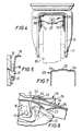
- Figure 1 is a plan view of the castor;
- Figure 2 is a partly sectioned side elevation of the castor, the section being on the line II-II in Figure 1, the castor being shown with the brake released;
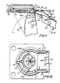
- Figure 3 is a view of the castor, from below as seen in Figure 2, with the wheel and its axle removed to show hidden detail;
- Figure 4 is an end elevation of the castor as seen from the right in Figure 2;
- Figure 5 is a sectioned detail of Figure 4 drawn to a larger scale;
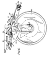
- Figure 6 is a view smaller to Figure 2 but showing the pedal brake applied;
- Figure 7 is a section on the line VII-VII in Figure 1 of the release level;
- Figure 8 is a detail of Figure 6 drawn to a larger scale and sectioned on the line VIII-VIII in Figure 1;
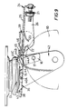
- Figure 9 is a partly-sectioned side elevation, similar to Figure 2, but with the hub assembly in elevation and showing a modified form of the leaf spring and of the release lever;
- Figure 10 is a fragmentary view similar to that of the corresponding part of Figure 3 showing the modification to the leaf spring illustrated in Figure 9; and
- Figure 11 is a fragmentary view, similar to the corresponding part of Figure 6, showing the modified leaf spring and release lever shown in Figure 9, when the brake is applied.
- Figures 1 to 8 of the drawings show a castor comprising a
wheel 10 which is journalled on anaxle 11 in afork 12. Thefork 12 is an inverted U comprising two triangular side portions depending from either side of a connecting body piece. The latter, which is referred to from now on as the bridge, is formed with an aperture which receives ahub assembly 13. Thehub assembly 13 includes a double rolling bearing (see Figure 2) by which thefork 12 is arranged for swivelling movement about the axis of thehub assembly 13 which is normal to but laterally offset from the axis of theaxle 11. - The underside of the
hub assembly 13 is formed with a circumferential array of recesses 14 (see Figure 3). - A
leaf spring 15 extends between thewheel 10 and the underside of the bridge of thefork 12 in a direction which is substantially parallel to the path thewheel 10 traces as it rolls. A major part of theleaf spring 15 is flat in its normal relaxed condition. Twolegs 16 depend from theleaf spring 15, one on either side. Eachleg 16 is journalled on arespective pivot peg 17 which projects from the inner face of a respective one of the side portions of thefork 12 towards the other side portion of the fork 12 (see Figure 5). Figure 3 shows that the end of theleaf spring 15 that is nearer to thehub assembly 13 is forked to form two spacedprongs 18, one on either side of the lower portion of thehub assembly 13 that projects below the bridge of thefork 12. Eachprong 18 has an upstanding angled end piece (see Figure 2) which engages the underside of the bridge of thefork 12. Theleaf spring 15 also has an integralcentral portion 19 which projects between the twoprongs 18. Thecentral portion 19 is cranked to form a dog leg, the toe end of which is below theprongs 18. Two upwardly-projectingprotuberances 20 are formed in thecentral portion 19 at substantially the same radial distance from the axis of thehub assembly 13 as the circumferential array ofrecesses 14, and are spaced apart angularly by substantially the same arc as two of therecesses 14 which are separated, conveniently by five other of therecesses 14. Eachprotuberance 20 is sized and shaped to seat neatly in a respective one of therecesses 14. There is a dependingflange 21 at the end of theleaf spring 15 remote from theprongs 18. - Two
tongues leaf spring 15, are formed by cut outs in theleaf spring 15, between thelegs 16 and theflange 21. Thetongues leaf spring 15, converge towards one another, each being in the form of a dog leg, and serve as sprag brakes which are operable to be urged into engagement with the circumferential periphery of thewheel 10 whereby to retard rotation of thewheel 10 in either direction. - A
sheet metal pedal 24 comprises a flatmain portion 25 and anintegral flange 26 which depends from the sides and one end of themain portion 25 to form a U in plan as seen in Figure 3. Anadjustment screw 27 is captive in the portion of theflange 26 at the end of themain portion 25, and has its threaded stem extending through an aperture in theflange 21 into engagement with anut 28 which is clipped to theflange 21. Themain portion 25 extends over theleaf spring 15 to a location between thelegs 16 and thetongues main portion 25 exceeds the width of theleaf spring 15 and of the tread of thewheel 10 so that the portions of theflange 26 that depend from the sides of themain portion 25 extend on either side of both of theleaf spring 15 and part of the wheel 10 (see Figures 2 and 6). - A sheet metal release lever 29 which, like the
fork 12, has an inverted U-shape (see Figure 7), extends over thepedal 24 at the end of the latter that is nearer to thehub assembly 13, the side portions of thelever 29 extending one on either side of thepedal 24 and towards the axis of thehub assembly 13 below the latter. Each side portion of thelever 29 has a T-shaped recess 31 formed in it, the two arms of the T-shaped recess 31 being at the bottom of therecess 31 and having arcuate ends. In the conditions shown in Figures 2 and 6, the arcuate end of the arm of each T-shaped recess 31 that is nearer to thehub assembly 13 receives thepivot pin 17 that therespective leg 16 of theleaf spring 15 is journalled upon. The medial portion of the release lever 29 rests on top of thepedal 24. It has alateral fold 32 between its ends, thefold 32 forming an upstanding ridge in its upper surface and a complementary trough in its underside, the ridge and trough extending from side to side of the medial portion. The part of the medial portion between thefold 32 and thehub assembly 13 has a top hat section, the raisedcentral portion 33 being in abutment with the adjacent edge of the bridge of thefork 12. The spaced lowerflat side portions 34 of the top hat section portion project into the gap between thewheel 10 and the bridge of thefork 12 with a clearance between them and the bridge (see Figure 8). - In the brake released condition shown in Figure 2, the
leaf spring 15 is in its flat relaxed state, thesprag brake tongues protuberances 20 at the end of the leaf springcentral portion 19 are displaced from the alignedrecesses 14 formed in thehub assembly 13. - To apply the brake, an operator puts his foot on the end of the
pedal 24 remote from thehub assembly 13. Theleaf spring 15 is bowed as shown in Figure 6, theprongs 18 reacting against the underside of the connecting body piece, and theprotuberances 20 are urged into engagement each with an aligned one of therecesses 14 whereby thefork 12 is locked against swivelling movement relative to thehub assembly 13. At the same time thesprag brake tongues wheel 10 so that thewheel 10 is held against rotation in either direction. Also the edge of themain portion 25 of thepedal 24 at the end which is not flanged is caused to slide along the underside of the twoside portions 34 of therelease lever 29, away from thefork 12, until it is snapped into the trough formed by the underside of thefold 32, as shown in Figure 8. The flatmain portion 25 of thepedal 24 serves as a strut so that, when engaged with the spaced abutments formed by the portions of thefold 34 that flank the raisedcentral portion 33, it holds theleaf spring 15 bowed, as shown in Figure 6. - To release the brake, the operator puts his foot on the end of the
release lever 29 that is further from thefork 12 so that therelease lever 29 is pivotted about the end surface of the fork bridge with which it is in abutment. The pivot pins 17 are disengaged from the respective arcuate ends of the arms of the T-shapedrecesses 31 with which they were engaged as shown in Figures 2 and 6. Engagement of the edge of the trough remote from the top hat section portion of therelease lever 29 with the flatmain portion 25 of thepedal 24 displaces the pedal 24 from the trough. Hence theleaf spring 15 is released to return to its normal flat condition as shown in Figure 2 to which it is urged in reaction to the engagement of theprongs 18 against the underside of the bridge. - The relative positioning of the
pedal 24 and therelease lever 29 can be adjusted by operation of the adjustment nut andscrew mechanism - Figures 9 to 11 show a modified form of the castor shown in Figures 1 to 8. Parts of the castor shown in Figures 9 to 11, which are similar to corresponding parts of the castor shown in Figures 1 to 8, are identified by the same reference numeral as is used in Figures 1 to 8. The modifications are to the part of the
leaf spring 35 that is in the region of thehub assembly 13, to therelease lever 39 and to the pivoted association of therelease lever 39 with the bridge of thefork 42. - Figure 10 shows the part of the
leaf spring 35 that is in the region of thehub assembly 13 is annular, having a central aperture through which the axis of thehub assembly 13 passes. The annular portion of theleaf spring 35 is symmetrical about the longitudinal axis of theleaf spring 35 which intersects the axis of thehub assembly 13. It replaces the two spacedprongs 18 and the integralcentral portion 19 of theleaf spring 15 shown in Figures 1 - 8. - The annular portion of the
leaf spring 35 is deformed by pressing at three circumferentially spaced locations to form three upwardly projectingprotuberances - The
protuberance 38 is located centrally at the end of theleaf spring 35 remote from thepedal 24. It extends below and projects radially outwardly beyond the adjacent rim portion of the bridge of thefork 42 which it engages, thereby serving the same functions as the upstanding angled end pieces of theprongs 18 of the castor shown in Figures 1 - 8. - The
protuberances leaf springs 35, are intended to cooperate with the circumferential array ofrecesses 14 in basically the same way as do theprotuberances 20 of the castor shown in Figures 1 - 8. - Figures 9 and 11 shows the
release lever 39 is hinged to the bridge of thefork 42 instead of being interengaged with the pivot pins 17 and pivoted about the adjacent edge of that bridge as in the castor shown in Figures 1 - 8. Therelease lever 39, which, like therelease lever 29, has an inverted U-shape and extends over thepedal 24, has twointegral hinge elements 44 which project from it at its end adjacent thefork 42. - Each
hinge element 44 is stepped, comprising aroot portion 44A which extends from the medial portion of the major U-shaped portion of therelease lever 39 below the adjacent rim portion of the bridge of thefork 42, anintermediate portion 44B which extends with clearance up through arespective aperture 45 in the bridge of thefork 42, and anend portion 44C which extends towards thehub assembly 13 above the bridge of thefork 42. The depth of eachaperture 45 is sufficiently less than the height of the respective intermediatehinge element portion 44B to allow a limited amount of angular movement of therelease lever 29 relative to thefork 42 about the hinge between them. The medial portion of therelease lever 39 has alateral fold 46 between its ends, thefold 46 forming an upstanding ridge in its upper surface and a complementary trough in its underside, the ridge and the trough extending from side to side of the medial portion. - In the brake released condition shown in Figure 9, the
leaf spring 35 is in its flat relaxed state, thesprag brake tongues protuberances hub assembly 13. Theleaf spring 35 reacts against therim portion 43 of the bridge of thefork 42 to hold the pedal 24 in its brake released location. Therelease lever 39 rests on the pedal 24 at the end of the latter that is adjacent to thehub assembly 13, the medial portion of therelease lever 39 and the flatmain portion 25 of the pedal 24 diverging away from that end and forming a tapered space between them. The angle between theend portion 44C and theintermediate portion 44B of each of thehinge elements 44 rests on the step formed by the top of the bridge of thefork 42 and the inner surface of therespective aperture 45. The medial portion of thelever 39 is at an angle to the bridge of thefork 42 sloping upwardly from theroot portions 44A of thehinge elements 44 to pass close to, or touch the edge of the bridge of thefork 42. - To apply the brake, an operator puts his foot on the end of the pedal 24 remote from the
assembly 13. Theleaf spring 35 is bowed in much the same way as is shown in Figure 6 for theleaf spring 15, theprotuberance 38 reacting against therim portion 43 of the fork bridge, and theprotuberances fork 42 is locked against swivelling movement relative to thehub assembly 13. At the same time thesprag brake tongues main portion 25 of the pedal 24 at the end which is not flanged is caused to slide along the underside of the medial portion of therelease lever 39, away from thefork 42, until it is snapped into the trough formed by the underside of thefold 46, in substantially the same way as is shown in Figure 6 for engagement of the pedal in thefold 42 of therelease lever 29. - To release the brake, the operator puts his foot on the end of the
release lever 39 that is further from thefork 42 so that therelease lever 39 is pivotted about the inner edges of theapertures 45. Engagement of the edge of the trough remote from thehub assembly 13 with the flatmain portion 25 of thepedal 24 displaces the pedal 24 from the trough. Hence theleaf spring 35 is released to return to its normal flat condition as shown in Figure 9 to which it is urged in reaction to the engagement of theprotrusion 38 with the bridgepiece rim portion 43. - The pivot pegs 17 are difficult and costly to make. It has been proposed that split, hardened spring steel tubes might be used as such pivot pins 17, each tube being spigotted into a respective aperture in the respective side portion of the
fork
Claims (13)
- A castor comprising a wheel (10) which is journalled on an axle (11) in a fork (12, 42) which is arranged for swivelling movement about an axis which is normal to the axis of the axle (11), the fork carrying a pedal operable brake for the wheel which is operable to put a braking element (22, 23) into braking engagement with the circumferential periphery of the wheel (10) when it is applied, the pedal operable brake comprising a pedal (24) and including a releasable latching arrangement comprising a leaf spring (15, 35) which extends above the wheel (10) substantially parallel to the path the wheel (10) traces as it rolls, which interacts with the pedal (24) and the fork (12, 42) so that it is flexed from its natural flat relaxed condition when the pedal (24) is depressed to apply the brake, and which is releasably held so flexed by interengagement of a strut portion (25) carried by the leaf spring (15, 35) with an abutment carried by the fork (12, 42) to hold the leaf spring (15, 35) flexed from its natural relaxed condition and the brake applied until the strut portion (25) is dislodged from engagement with the abutment to free the pedal (24) and release the brake by the action of the return of the leaf spring (15, 35) to its natural flat relaxed condition, characterised in that the abutment is formed in a recess in a surface along which an edge of the strut portion (25) remote from the leaf spring (15, 35) is caused to slide as the pedal (24) is depressed, the edge of the strut portion (25) being snapped into the recess and thus into engagement with the abutment at the end of the brake applying movement of the pedal (24) whereby the edge of the strut portion (25) is positively located in engagement with the abutment by the recess.
- A castor according to claim 1, wherein the braking element is a sprag (22, 23) formed by a respective tongue which is integral with the leaf spring (15, 35) and which depends from the leaf spring (15, 35) towards the wheel (10).
- A castor according to claim 2, wherein the sprag is one of an opposed pair of such sprags (22, 23) which converge towards the wheel (10) for braking rotation of the wheel (10) in either direction.
- A castor according to any one of claims 1 to 3, wherein the leaf spring (15, 35) has a protuberance (20, 40A, 40B) which is adapted to engage an aligned one of a circumferential array of corresponding recesses (14) formed in a hub assembly (13) upon which the fork (12, 42) is journalled for swivelling movement about the axis which is normal to the axis of the wheel axle (11), the protuberance (20, 40A, 40B) being spaced from the recesses (14) in the hub assembly when the leaf spring (15, 35) is in its natural flat relaxed condition and being urged in a direction which is substantially parallel to the axis of the hub assembly (13) into engagement with the aligned one of the recesses (14) in the hub assembly (13) by the action of deforming the leaf spring (15, 35) to apply the brake, so that the fork (12, 42) is locked against swivelling movement about the axis that is normal to the axis of the wheel axle (11) when the brake is applied.
- A castor according to claim 4, wherein the leaf spring (15) is forked at an end remote from the pedal (24), the forked end forming two spaced integral prong portions (18) which engage the fork (12).
- A castor according to claim 5, wherein the protuberance (20) is formed in an integral projecting portion (19) of the leaf spring (15) which projects between the two prong portions (18).
- A castor according to claim 4, wherein the leaf spring (35) reacts against the fork (42) at an end remote from the pedal (24) and the protuberance (40A, 40B) is formed in the leaf spring (35) between said end and the pedal (24).
- A castor according to claim 7, wherein the protuberance is one of a pair of such protuberances (40A and 40B) which are formed in the leaf spring (35) symmetrically on either side of the longitudinal axis of the leaf spring (35).
- A castor according to claim 8, wherein the part of the leaf spring (35) that reacts against the fork (42) at said end and the two protuberances (40A and 40B) are circumferentially spaced around an annular portion of the leaf spring (35), the annular portion having a central aperture through which the axis of the hub assembly (13) passes.
- A castor according to any one of claims 1 to 9, wherein the abutment is formed in a release lever (29, 39) which is pivotally mounted in the fork (12, 42) and which is urged into abutment with the fork (12, 42) by the action of the stressed leaf spring (15, 35) acting through the strut element (25) that is engaged with the abutment, the arrangement being such that the release lever (29, 39) can be pivoted relative to the fork (12, 42) to dislodge the strut element (25) from engagement with the abutment and thereby to release the stressed leaf spring (15, 35) for return movement to its natural flat relaxed position.
- A castor according to claim 10, wherein the release lever (29, 39) is a secondary pedal.
- A castor according to claim 10 or claim 11, wherein the release lever (29) is pivotally mounted on a pivot (17) carried by a side portion of the fork (12) and is urged into abutment with a surface on the bridge piece of the fork (12) by the action of the stressed leaf spring (15) acting through the strut element (25) that is engaged with the abutment, the pivot (17) being engaged within a corresponding recess (31) which is formed in the release lever (29) so that it is open on one side, the arrangement being such that the pivot (17) is disengaged from the corresponding recess (31) by pivotal movement of the release lever (29) about said surface of the fork (12) whereby to allow the strut element to be displaced from engagement with the abutment and thereby to release the stressed release spring (15) for return movement to its natural flat relaxed condition, the release lever (29) being restored to its normal position in abutment with said surface and with the pivot (17) engaged within the corresponding open sided recess (31) due to the action of the leaf spring (15) as it returns to its normal flat relaxed condition.
- A castor according to claim 10 or claim 11, wherein the release lever (39) is hinged to the bridge piece of the fork (42) by the engagement of hinge elements (44) which project from the release lever (39) through corresponding apertures (45) formed in the bridge piece.
Priority Applications (1)
| Application Number | Priority Date | Filing Date | Title |
|---|---|---|---|
| AT87307682T ATE69409T1 (en) | 1986-08-29 | 1987-08-28 | CASTER. |
Applications Claiming Priority (2)
| Application Number | Priority Date | Filing Date | Title |
|---|---|---|---|
| GB8620924 | 1986-08-29 | ||
| GB868620924A GB8620924D0 (en) | 1986-08-29 | 1986-08-29 | Castor |
Publications (3)
| Publication Number | Publication Date |
|---|---|
| EP0259131A2 EP0259131A2 (en) | 1988-03-09 |
| EP0259131A3 EP0259131A3 (en) | 1988-12-07 |
| EP0259131B1 true EP0259131B1 (en) | 1991-11-13 |
Family
ID=10603397
Family Applications (1)
| Application Number | Title | Priority Date | Filing Date |
|---|---|---|---|
| EP87307682A Expired EP0259131B1 (en) | 1986-08-29 | 1987-08-28 | A castor |
Country Status (6)
| Country | Link |
|---|---|
| EP (1) | EP0259131B1 (en) |
| AT (1) | ATE69409T1 (en) |
| AU (1) | AU601475B2 (en) |
| CA (1) | CA1303307C (en) |
| DE (1) | DE3774512D1 (en) |
| GB (1) | GB8620924D0 (en) |
Cited By (1)
| Publication number | Priority date | Publication date | Assignee | Title |
|---|---|---|---|---|
| US20130227817A1 (en) * | 2010-11-15 | 2013-09-05 | Tente Gmbh & Co. Kg | Roller |
Families Citing this family (8)
| Publication number | Priority date | Publication date | Assignee | Title |
|---|---|---|---|---|
| DE3717896A1 (en) * | 1987-05-27 | 1988-12-15 | Schulte Soehne Gmbh Co A | STEERING WHEEL WITH A LOCKING DEVICE |
| DE4035195A1 (en) * | 1990-11-06 | 1992-05-07 | Schulte Soehne Gmbh Co A | Method of concealing locking mechanism for castor |
| FR2703300B1 (en) * | 1993-03-30 | 1995-06-30 | Guitel Etienne Mobilor | PIVOTING CASTER WITH DIRECTIONAL LOCK. |
| FR2747615B1 (en) * | 1996-04-22 | 1998-06-12 | Soc D Expl De La Manufacture P | ROULETTE DESTINED, ESPECIALLY FOR TROLLEYS, BINS OR THE LIKE |
| GB9618632D0 (en) * | 1996-09-06 | 1996-10-16 | Twil Handling & Display Ltd | Brake mechanism |
| DE19836454C2 (en) * | 1998-08-12 | 2000-06-08 | Steinco Paul Vom Stein Gmbh | Braked castor for apparatus, devices, furniture or the like |
| ITMI20010421U1 (en) * | 2001-07-24 | 2003-01-24 | Ogtm Officine Meccaniche Srl | STRUCTURE OF SWIVEL WHEEL |
| CN107336564B (en) * | 2017-07-28 | 2023-06-30 | 中山威卡脚轮有限公司 | Movable castor with light braking device |
Family Cites Families (2)
| Publication number | Priority date | Publication date | Assignee | Title |
|---|---|---|---|---|
| DE1918357A1 (en) * | 1969-04-11 | 1970-11-12 | Hufa Rollen Kg | Swivel castor |
| AU416849B2 (en) * | 1970-04-03 | 1971-08-31 | To Flexello Castors & Wheels Limited | Control mechanism particularly for braking devices |
-
1986
- 1986-08-29 GB GB868620924A patent/GB8620924D0/en active Pending
-
1987
- 1987-08-27 CA CA000545581A patent/CA1303307C/en not_active Expired - Lifetime
- 1987-08-27 AU AU77499/87A patent/AU601475B2/en not_active Ceased
- 1987-08-28 AT AT87307682T patent/ATE69409T1/en not_active IP Right Cessation
- 1987-08-28 EP EP87307682A patent/EP0259131B1/en not_active Expired
- 1987-08-28 DE DE8787307682T patent/DE3774512D1/en not_active Expired - Fee Related
Cited By (2)
| Publication number | Priority date | Publication date | Assignee | Title |
|---|---|---|---|---|
| US20130227817A1 (en) * | 2010-11-15 | 2013-09-05 | Tente Gmbh & Co. Kg | Roller |
| US9481206B2 (en) * | 2010-11-15 | 2016-11-01 | Tente Gmbh & Co. Kg | Roller |
Also Published As
| Publication number | Publication date |
|---|---|
| AU7749987A (en) | 1988-03-03 |
| DE3774512D1 (en) | 1991-12-19 |
| EP0259131A3 (en) | 1988-12-07 |
| EP0259131A2 (en) | 1988-03-09 |
| ATE69409T1 (en) | 1991-11-15 |
| CA1303307C (en) | 1992-06-16 |
| GB8620924D0 (en) | 1986-10-08 |
| AU601475B2 (en) | 1990-09-13 |
Similar Documents
| Publication | Publication Date | Title |
|---|---|---|
| EP0259131B1 (en) | A castor | |
| US3493085A (en) | Positive locking caster brake | |
| US20090276977A1 (en) | Selectively lockable caster | |
| US6298950B1 (en) | Steering roller | |
| CA1232720A (en) | Brake for twin wheel casters | |
| GB2205035A (en) | Castor wheel provided with a locking device | |
| CA1309216C (en) | Twin wheel caster with integral brake assembly | |
| CZ285469B6 (en) | Turning wheel | |
| US4664231A (en) | Braked castors | |
| US4363520A (en) | Wheel cover retention | |
| EP0038197A1 (en) | Dual wheel caster assembly | |
| US5875572A (en) | Toolless shoe spike | |
| CA2920974A1 (en) | Brake pad of a disk brake, and disk brake | |
| GB2148109A (en) | Castors | |
| CA1091726A (en) | Retainer for wheel trim | |
| CA1098060A (en) | Friction clutch apparatus | |
| GB2155321A (en) | Improvements in and relating to castors | |
| EP0352380B2 (en) | Castor | |
| GB2075438A (en) | Wheel cover with retention means | |
| CN101861248B (en) | Device and method for preventing wheel component rotation of truckle | |
| US5943735A (en) | Shopping trolley, a castor for a shopping trolley and a kit of parts for fitting to such a castor | |
| US4843677A (en) | Tilted axle caster with brake | |
| JPH068005U (en) | Caster brake | |
| GB2204485A (en) | Locking device for castor wheels | |
| JP2607715Y2 (en) | Casters with braking device |
Legal Events
| Date | Code | Title | Description |
|---|---|---|---|
| PUAI | Public reference made under article 153(3) epc to a published international application that has entered the european phase |
Free format text: ORIGINAL CODE: 0009012 |
|
| AK | Designated contracting states |
Kind code of ref document: A2 Designated state(s): AT BE DE FR GB IT NL SE |
|
| PUAL | Search report despatched |
Free format text: ORIGINAL CODE: 0009013 |
|
| AK | Designated contracting states |
Kind code of ref document: A3 Designated state(s): AT BE DE FR GB IT NL SE |
|
| 17P | Request for examination filed |
Effective date: 19890510 |
|
| 17Q | First examination report despatched |
Effective date: 19900102 |
|
| GRAA | (expected) grant |
Free format text: ORIGINAL CODE: 0009210 |
|
| AK | Designated contracting states |
Kind code of ref document: B1 Designated state(s): AT BE DE FR GB IT NL SE |
|
| REF | Corresponds to: |
Ref document number: 69409 Country of ref document: AT Date of ref document: 19911115 Kind code of ref document: T |
|
| ITF | It: translation for a ep patent filed | ||
| REF | Corresponds to: |
Ref document number: 3774512 Country of ref document: DE Date of ref document: 19911219 |
|
| ET | Fr: translation filed | ||
| PG25 | Lapsed in a contracting state [announced via postgrant information from national office to epo] |
Ref country code: GB Effective date: 19920828 Ref country code: AT Effective date: 19920828 |
|
| PG25 | Lapsed in a contracting state [announced via postgrant information from national office to epo] |
Ref country code: SE Effective date: 19920829 |
|
| PG25 | Lapsed in a contracting state [announced via postgrant information from national office to epo] |
Ref country code: BE Effective date: 19920831 |
|
| PLBE | No opposition filed within time limit |
Free format text: ORIGINAL CODE: 0009261 |
|
| STAA | Information on the status of an ep patent application or granted ep patent |
Free format text: STATUS: NO OPPOSITION FILED WITHIN TIME LIMIT |
|
| 26N | No opposition filed | ||
| BERE | Be: lapsed |
Owner name: FLEXELLO CASTORS & WHEELS P.L.C. Effective date: 19920831 |
|
| PG25 | Lapsed in a contracting state [announced via postgrant information from national office to epo] |
Ref country code: NL Effective date: 19930301 |
|
| NLV4 | Nl: lapsed or anulled due to non-payment of the annual fee | ||
| GBPC | Gb: european patent ceased through non-payment of renewal fee |
Effective date: 19920828 |
|
| PG25 | Lapsed in a contracting state [announced via postgrant information from national office to epo] |
Ref country code: FR Effective date: 19930430 |
|
| PG25 | Lapsed in a contracting state [announced via postgrant information from national office to epo] |
Ref country code: DE Effective date: 19930501 |
|
| REG | Reference to a national code |
Ref country code: FR Ref legal event code: ST |
|
| EUG | Se: european patent has lapsed |
Ref document number: 87307682.2 Effective date: 19930307 |
|
| PG25 | Lapsed in a contracting state [announced via postgrant information from national office to epo] |
Ref country code: IT Free format text: LAPSE BECAUSE OF NON-PAYMENT OF DUE FEES;WARNING: LAPSES OF ITALIAN PATENTS WITH EFFECTIVE DATE BEFORE 2007 MAY HAVE OCCURRED AT ANY TIME BEFORE 2007. THE CORRECT EFFECTIVE DATE MAY BE DIFFERENT FROM THE ONE RECORDED. Effective date: 20050828 |