EP0259019A1 - Single cylinder type switching valve for mixing hot and cold water - Google Patents
Single cylinder type switching valve for mixing hot and cold water Download PDFInfo
- Publication number
- EP0259019A1 EP0259019A1 EP19870306984 EP87306984A EP0259019A1 EP 0259019 A1 EP0259019 A1 EP 0259019A1 EP 19870306984 EP19870306984 EP 19870306984 EP 87306984 A EP87306984 A EP 87306984A EP 0259019 A1 EP0259019 A1 EP 0259019A1
- Authority
- EP
- European Patent Office
- Prior art keywords
- switching valve
- hot
- inlets
- sliding surface
- cold water
- Prior art date
- Legal status (The legal status is an assumption and is not a legal conclusion. Google has not performed a legal analysis and makes no representation as to the accuracy of the status listed.)
- Granted
Links
Images


Classifications
-
- F—MECHANICAL ENGINEERING; LIGHTING; HEATING; WEAPONS; BLASTING
- F16—ENGINEERING ELEMENTS AND UNITS; GENERAL MEASURES FOR PRODUCING AND MAINTAINING EFFECTIVE FUNCTIONING OF MACHINES OR INSTALLATIONS; THERMAL INSULATION IN GENERAL
- F16K—VALVES; TAPS; COCKS; ACTUATING-FLOATS; DEVICES FOR VENTING OR AERATING
- F16K11/00—Multiple-way valves, e.g. mixing valves; Pipe fittings incorporating such valves
- F16K11/10—Multiple-way valves, e.g. mixing valves; Pipe fittings incorporating such valves with two or more closure members not moving as a unit
- F16K11/14—Multiple-way valves, e.g. mixing valves; Pipe fittings incorporating such valves with two or more closure members not moving as a unit operated by one actuating member, e.g. a handle
-
- F—MECHANICAL ENGINEERING; LIGHTING; HEATING; WEAPONS; BLASTING
- F16—ENGINEERING ELEMENTS AND UNITS; GENERAL MEASURES FOR PRODUCING AND MAINTAINING EFFECTIVE FUNCTIONING OF MACHINES OR INSTALLATIONS; THERMAL INSULATION IN GENERAL
- F16K—VALVES; TAPS; COCKS; ACTUATING-FLOATS; DEVICES FOR VENTING OR AERATING
- F16K11/00—Multiple-way valves, e.g. mixing valves; Pipe fittings incorporating such valves
- F16K11/02—Multiple-way valves, e.g. mixing valves; Pipe fittings incorporating such valves with all movable sealing faces moving as one unit
- F16K11/06—Multiple-way valves, e.g. mixing valves; Pipe fittings incorporating such valves with all movable sealing faces moving as one unit comprising only sliding valves, i.e. sliding closure elements
- F16K11/078—Multiple-way valves, e.g. mixing valves; Pipe fittings incorporating such valves with all movable sealing faces moving as one unit comprising only sliding valves, i.e. sliding closure elements with pivoted and linearly movable closure members
-
- G—PHYSICS
- G05—CONTROLLING; REGULATING
- G05D—SYSTEMS FOR CONTROLLING OR REGULATING NON-ELECTRIC VARIABLES
- G05D23/00—Control of temperature
- G05D23/01—Control of temperature without auxiliary power
- G05D23/13—Control of temperature without auxiliary power by varying the mixing ratio of two fluids having different temperatures
- G05D23/1393—Control of temperature without auxiliary power by varying the mixing ratio of two fluids having different temperatures characterised by the use of electric means
Landscapes
- Engineering & Computer Science (AREA)
- General Engineering & Computer Science (AREA)
- Mechanical Engineering (AREA)
- Physics & Mathematics (AREA)
- General Physics & Mathematics (AREA)
- Automation & Control Theory (AREA)
- Multiple-Way Valves (AREA)
Abstract
Description
- The present invention relates to a single cylinder type switching valve to be ordinarily used for a mixture cock for mixing hot and cold waters for exhausting, stopping or mixing the hot and cold waters.
- A conventional single cylinder type switching valve of this type is composed in a cylindrical shape to open or close inlets for hot and cold waters and to adjust the mixture amount of the hot and cold waters in the same valve body, and operates to open or close the inlets for the hot and cold waters by axially moving the cylindrical valve body and to reversibly adjust the openings of the inlets for the hot and cold waters by turning the valve body to adjust the mixture amount of the hot and cold waters.
- The cylindrical valve body of the conventional switching valve is sealed only by sealing means of O-rings made of rubber or synthetic resin provided at the cylinder side. The O-rings are vigorously worn or damaged by foreign materials such as sand, gravel, rust pieces of pipes mixed in the hot and cold waters to be supplied, and thus has disadvantages that the O-rings early leak the waters.
- Calcium, iron, cake and/or a sterilizer such as a chlorine contained in the water to be supplied are adhered to the O-rings to early deteriorate the O-rings, to increase the sliding resistance of the O-rings with the valve body, and the switching valve thus has disadvantages that much greater strength than that at the initial time is required to operate the switching valve.
- Even if the sliding surface of the valve body of the switching valve is coated with a lubricant to reduce the sliding resistance of the O-rings with the valve body, the cylindrical valve body is axially moved to open or close the inlets for the hot and cold waters and is rotatably adjusted in the openings of the inlets for the hot and cold waters. Thus, the sliding surface of the valve body contacted with the hot and cold waters is extended in a wide range, and the lubricant coated on the sliding surface is immediately flushed away so that it is very difficult to maintain the initial sliding state on the sliding surface.
- A conventional switching valve, wherein a cylindrical valve body and a cylinder are formed of a stainless steel or a ceramic material having less chemical change, less wear and high hardness to enhance the strengths of the valve body and the cylinder has been proposed, but it is difficult to precisely finish the cylindrical shape with the high hardness material. Even if the cylindrical valve body and the cylinder are formed of the high hardness materials, the sealing with the O-rings is still indispensable.
- In view of the foregoing, one object of the present invention is to eliminate the disadvantages of the conventional switching valve and to provide a single cylinder type switching valve for mixing hot and cold waters, wherein inlets for hot and cold waters are planely sealed by smooth surfaces of smooth guide sliding surface formed inside a cylinder and smooth sliding surface of the switching valve to eliminate the use of O-rings to be readily damaged to improve the enduring lifetime.
- Another object of the present invention is to provide a single cylinder type switching valve for mixing hot and cold waters, wherein inlets for hot and cold waters are planely sealed by smooth surfaces of smooth guide sliding surface formed inside a cylinder and smooth sliding surface of the switching valve so that the smooth sliding surface of the switching valve and the smooth guide sliding surface formed inside the cylinder are readily formed of a material having less chemical change, less wear, inorganic high hardness such as, for example, special steel, stainless steel, ceramic, or new ceramic to be easily finished to provide excellent sealing effect in the switching valve and to improve the enduring lifetime.
- Yet another object of the present invention is to provide a single cylinder type switching valve for mixing hot and cold waters, wherein a switching valve for opening or closing inlets for the hot and cold waters and a mixture valve for adjusting the inlets for the hot and cold waters in the opening are separately formed to operate to feed or stop the inlets for the hot and cold waters in a very small range of reciprocating along the axial direction of the cylinder to thereby reduce the flushing amount of lubricant coated on the sliding surface of the switching valve, to thus maintain the sliding resistance reducing state with the coated lubricant, thereby suppressing the wear on the sliding surface for a long period or time.
- Still another object of the present invention is to provide a single cylinder type switching valve for mixing hot and cold waters, wherein a mixture valve for adjusting the inlets for the hot and cold waters in the opening is contained in the switching valve to have a simple structure that does not need a sufficient sealing mechanism in the mixture valve.
- These and other objects as may become apparent hereinafter have been attained by a single cylinder type switching valve for mixing hot and cold waters comprising a cylinder opened with inlets for hot and cold waters and an outlet for hot and cold mixture water, a smooth guide sliding surface including the openings in the inlets for the hot and cold waters inside the cylinder and formed along the axial direction of the cylinder, a smooth sliding surface opposed to the smooth guide sliding surface formed inside the cylinder, a switching valve opened with switching inlets for the hot and cold waters corresponding to the inlets for the hot and cold waters in the cylinder and slidably provided to the axial direction of the cylinder on the sliding surfaces, and a mixture valve for opening or closing the switching inlets for the hot and cold waters inside the switching valve.
- For a better understanding of the invention as well as other objects and further features thereof, preferred embodiments of the invention will be explained with reference to the accompanying drawings in which:
- FIG. 1 is an exploded perspective view of an essential portion of a single cylinder type switching valve for mixing hot and cold waters according to the present invention;
- FIG. 2 is a longitudinal sectional side view showing the closed state of inlets for hot and cold waters of the switching valve;
- FIG. 3 is a longitudinal sectional side view showing the opened state of inlets for hot and cold waters of the switching valve;
- FIGS. 4 to 8 are longitudinal sectional front views of essential portions of the opening adjusting state of the switching inlets for the hot and cold waters of a mixture valve;
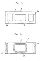
- FIGS. 9 to 12 are views exemplifying a watertight structure in the peripheral watertight areas of the inlets for the hot and cold waters of the cylinder, wherein FIG. 9 is a longitudinal side view, FIG. 10 is a longitudinal sectional front view, FIG. 11 is a front view of a smooth guide sliding surface side of a guide plate, and FIG. 12 is a back view of the guide plate; and
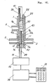
- FIGS. 13 to 18 are views showing an embodiment of the case that the switching valve is divided into hot and cold water side switching valves, wherein FIG. 13 is an exploded perspective view of the essential portion, FIGS. 14 to 16 are longitudinal sectional side views showing the switching states of the inlets for the hot and cold waters, FIG. 14 is the state that the inlets for the hot and cold waters are closed, FIG. 15 is the state that the inlets for the hot and cold waters are opened, FIG. 16 is the state that the openings of the inlets for the hot and cold waters are adjusted, FIG. 17 is a longitudinal sectional side view showing another embodiment, and FIG. 18 is a longitudinal sectional side view of still another embodiment.
- In FIGS. 1 to 3, a
cylinder 1 is formed in a cylindrical shape disposed in a mixture cock body and made of metal such as brass or synthetic resin material such as nylon or vinyl chloride. Thecylindrical cylinder 1 may be integrally molded, but may be split, molded, and combined. Aninlet 2 for supplying hot water is opened at the peripheral edge of one side of thecylinder 1. Aninlet 3 for supplying cold water is opened at the peripheral edge of thecylinder 1 radially oppositely to theinlet 2 opened at the peripheral edge of thecylinder 1. The opening positions of theinlets guide sliding surface 4 is formed along the axial direction of thecylinder 1 to include the opening of theinlet cylinder 1, and formed throughguide plates guide plates cylinder 1, or may be molded separately from theguide plate 5, and theguide plate 5 may be secured by means such as brazing to the inner surface of thecylinder 1. The smoothguide sliding surface 4 for forming its surface is preferably made of a material having less chemical change and less wear such as inorganic high hardness material, for example, special steel, stainless steel, ceramic, or new ceramic material, and it is further effective to mirror-finish the surface to cause a linking phenomenon when the smooth surfaces are superposed. Anoutlet 6 for hot and cold mixture water is opened at the position opposite axially to theinlets cylindrical cylinder 1 for exhausting the hot, cold water supplied into thecylinder 1 or their mixture water. A fixingengaging groove 7 integrally fixes thecylinder 1 to aholder 8 to engage an inner projection with the groove formed on theholder 8 and to engage an O-ring. Aswitching valve 9 opens or closes theinlets cylinder 1, and is formed in a cylinder having smooth slidingsurfaces guide sliding surfaces cylinder 1. Switchinginlets inlets cylinder 1 for the hot and cold waters are opened at the smoothsliding surfaces valve retainer 14 formed at the end of avalve shaft 13 slidably supported to theholder 8, and is held by acollar 15 formed at the intermediate portion of thevalve shaft 13 and aspring 16 formed at the inner bottom of theswitching valve 9. When the smooth slidingsurfaces switching valve 9 move axially of thevalve shaft 13 to slide along the smoothguide sliding surfaces cylinder 1 to open or close theinlets cylinder 1 in such a manner that theinlet 2 and theswitching inlet 11 coincide or displaces from each other and theinlet 3 and theswitching inlet 12 coincide or displaces from each other in response to the sliding position. The smooth slidingsurfaces switching valve 9 are preferably formed of a material having less chemical change and less wear such as inorganic high hardness material, for example, special steel, stainless steel, ceramic, or new ceramic material, and it is further effective to mirror-finish the surface to cause a linking phenomenon when the smoothguide sliding surfaces guide sliding surfaces opposed cylinder 1. When the smoothguide sliding surfaces surfaces entire guide plate 5 or switchingvalve 4 having theguide sliding surfaces 4 and the slidingsurface 10 are formed of the high hardness material. Amixture valve 17 is provided to reversibly adjust the openings of theswitching inlets switching valve 9 to adjust the hot and cold water mixture amount. Themixture valve 17 is composed as a cylindrical valve having a large opening at the side and is disposed in theswitching valve 9. Themixture valve 17 is held to thevalve shaft 13 by aspring 15 similarly to theswitching valve 9, and is integrally turned together with thevalve shaft 13 by akey 18 inserted into thevalve shaft 13. Since the mounting of theswitching valve 9 and themixture valve 17 on thevalve shaft 13 by thespring 16 eliminates the momentary simultaneous closing of both thevalves valves 9 and/or 17 are abruptly closed, but thevalves valve shaft 13 against thespring 16, and then gradually closed by the load of thespring 15, thereby preventing a water hammer phenomenon from occuring. The arrangement of themixture valve 17 is not limited to the exemplified example shown in the drawings, but may employ the mechanism known per se. Further, themixture valve 17 may employ means such as a method of using a thermostat element or a method of using a thermistor sensor. - The operation of the single cylinder type switching valve of the present invention will be described. The state that the
inlets cylinder 1 are closed by theswitching valve 9 is first shown in FIG. 2. - In the state shown in FIG. 2, when a
handle 19 provided at one end of thevalve shaft 13 is pulled rightward of FIG. 3, theswitching valve 9 moves rightward through thevalve shaft 13 so that theinlets 2 of thecylinder 1 and theswitching inlet 11 of theswitching valve 9 coincide, and theinlet 3 of thecylinder 1 and theswitching inlet 12 of theswitching valve 9 coincide to open theinlets switching valve 9. - When the
handle 19 is then rotated to turn themixture valve 17 through thevalve shaft 13, the openings of theinlets valves 9 alter as shown in FIGS. 4 to 8. More specifically, in the state of FIG. 4, theinlet 11 is closed, and only theinlet 12 is opened to supply only the cold water. In the state of FIG. 5, theinlet 11 is slightly opened, and theinlet 12 is slightly closed to supply and mix small amount of hot water and large amount of cold water. In the state of FIG. 6, theinlets inlet 11 is slightly closed and theinlet 12 is slightly opened to supply and mix large amount of hot water and small amount of cold water. Further, in the state of FIG. 8, only theinlet 11 is opened, and theinlet 12 is closed to supply only the hot water. The outlet water is exhausted in all the above cases from theoutlet 6. - Then, an example of a watertight structure of the watertight areas of the inlets for the hot and cold waters of the cylinder will be described with reference to FIGS. 9 to 12. In FIGS. 9 to 12, a
watertight area 20 for openinginlets cylinder 1 is split into apacking member 21 made of an elastic material such as rubber or flexible synthetic resin and aguide plate 5 made of a high hardness material such as special steel, stainless steel, ceramic or new ceramic material having a smoothguide sliding surface 4, and is composed by superposing thepacking member 21 and theguide plate 5 to be formed as a part of thecylinder 1. Thepacking member 21 has an outer peripheral surface bent similarly to thecylinder 1 and a watertight ring projected in a semicircular shape to surround theinlets core material 22 made of a metal plate. Thispacking member 21 is provided for absorbing the external pressure applied to thewatertight area 20. The smoothguide sliding surface 4 of theguide plate 5 is mirror-polished. Anengaging projecting strip 23 is provided on the superposing surfaces of theguide plate 5 on thepacking member 21, and is provided to surround theinlets guide plate 5 with thepacking member 21. Arecess 24 is formed on the smoothguide sliding surface 4 of theguide plate 5 contacted with thesliding surface 10 of theswitching valve 9 except a portion necessary for holding the watertightness, such as a peripheral edges of theinlets cylinder 1. The depth of therecess 24 is of the degree not losing the strength of theguide plate 5, in which range the recess may be formed in a through hole. Therecess 24 reduces the contacting area of the smooth slidingsurface 4 of theguide plate 5 with the slidingsurface 10 of theswitching valve 9 to thereby decrease the frictional resistance of the slide contacting surfaces thereof. Therecess 24 may be also utilized to contain lubricant such as silicone grease. The lubricant is supplied to the slide contacting surface with theswitching valve 9 to readily slide theswitching valve 9, and it is effective to utilize therecess 24 disposed at the position not contacted with the hot and cold waters even when theswitching valve 9 reciprocates as a lubricant containing chamber. - Another embodiment of the invention in which a switching valve is split into a hot water side switching valve and a cold water side switching valve will be described with reference to FIGS. 13 to 18.
- In FIGS. 13 to 18, a hot water
side switching valve 9a is provided to open or close aninlet 2 for hot water provided in acylinder 1, is provided to have a smooth slidingsurface 10a opposed to a smooth guide surface of a hot waterside guide plate 5a provided inside thecylinder 1, and a switchinginlet 11 for hot water corresponding to theinlet 2 provided in thecylinder 1 is opened at the smooth slidingsurface 10a. The the smooth sliding surface of the hot waterside switching valve 9a slides along the smooth guide surface of the hot waterside guide plate 5a provided in thecylinder 1 to open or close theinlet 2 of thecylinder 1 in such a manner that the theinlet 2 and the switchinginlets 11 coincide or displaces from each other, thereby adjusting the opening. A cold waterside switching valve 9b is provided to open or close aninlet 3 provided in thecylinder 1, is provided to have a smooth slidingsurface 10b opposed to the smooth guide surface of the colt waterside guide plate 5b provided in thecylinder 1 to open the switchinginlet 12 corresponding to theinlet 3 provided in thecylinder 1. The smooth slidingsurface 10b of the cold waterside switching valve 9b slides along the smooth guide surface of the cold waterside guide plate 5b provided in thecylinder 1 to open or close theinlet 3 of thecylinder 1 in such a manner that theinlet 3 and the switchinginlet 12 coincide or displaces from each other according to the sliding position to adjust the opening. The smooth slidingsurfaces side switching valves guide plates cylinder 1, and are mirror-polished to cause a linking phenomenon when the smooth guide surfaces of theguide plates - Since the opening or closing operation and opening adjusting operation of the
inlet 2 by the hot waterside switching valve 9a and the opening or closing operation and opening adjusting operation of theinlet 3 by the cold waterside switching valve 9b are carried out by the planely linear movement of the hot and cold waterside switching valves surfaces guide plates side switching valves valves surfaces side switching valve - It is general to separately operate the hot and cold water
side switching valves inlet 3 may be so set as to be decreased by the switchingvalve 9b when the opening of theinlet 2 is increased by the switchingvalve 9a and may be so set as to be increased by the switchingvalve 9b when the opening of theinlet 2 is decreased by the switchingvalve 9b, i.e., the switchingvalves inlets valves valves valves - In the embodiment exemplified in the drawings, the switching valve has the rack and the pinion. More particularly, in FIGS. 14 to 17, a
rack 25 is provided inside a hot waterside switching valve 9a, and arack 26 is provided inside a cold waterside switching valve 9b. Theracks pinion 27. Theracks pinion 27 are arranged at right and left sides, and may also be arranged only at the center. Apinion holder 28 rotatably supports thepinion 27. An opening or closingoperating lever 29 is contacted with thepinion holder 28 or athermostat element 20 supported to thepinion holder 28. When thelever 29 moves upward or downward,pinion 27 moves upward or downward to move upward or downward theswitching valves racks pinion 27 to open or close both theinlets inlets valves valves lever 29 rises to fully open theinlets lever 31 is contacted with the switchingvalve 9a to move upward or downward the switchingvalve 9b by the upward or downward movement thereof. When the mixinglever 31 is operated to move upward as shown in FIG. 16 to rise theswitching valve 9b, therack 26 provided in the switchingvalve 9b rotates thepinion 27 to move downward therack 25 and hence the switchingvalve 9a. Accordingly, theinlets inlets driver 32 has a driving mechanism for the operatinglever 29 and the mixinglever 31 to be controlled by amicrocomputer 34 operated on anoperation panel 33. - The embodiment in FIG. 17 shows the case that the switching
valves valve shaft 35 is slidably installed in aholder 8 through astopper 36. Though apinion holder 28 is supported to thevalve shaft 35, it is clamped by ascrew 27 to rotate thevalve shaft 35. Therefore, when thevalve shaft 35 is pulled or pushed by ahandle 38, thepinion holder 28 coupled to thevalve shaft 35 moves together to move the switchingvalves racks pinion 27 installed in the pinion holder to open or closes both theinlets cam 29 is formed as an oblique surface on the end of the switchingvalve 9b, and is contacted with a cam clutch 40 slidably provided by a spline with thevalve shaft 35. Aspring 41 is provided between thecam clutch 40 and thestopper 35 provided on thevalve shaft 39 to support the cam clutch 40 in contact. When thehandle 38 is rotated to rotate together with the cam clutch 40 to move upward the contacting surface along the oblique surface of thecam 39, thecam 39 and hence the switchingvalve 9b is moved down to reduce the opening (area) of theinlet 3, while therack 26 provided in the movingswitching valve 9b rotates thepinion 27 to move therack 35 and hence the switchingvalve 9b reversely to the switchingvalve 9b against thespring 43 provided between thethermostat element 30 and thespring retainer 42 of the switchingvalve 9a to increase the opening of theinlet 2, thereby increasing the mixture ratio of the hot water to the hot and cold water mixture. When thehandle 38 is rotated reversely to the above-mentioned case to rotate the cam clutch 40 together to move the contacting surface to move down along the oblique surface of thecam 39, the switchingvalves racks pinion 27 by the recoiling actions of thespring 41 provided on the back of thecam clutch 40 and thespring 43 compressed between thethermostat element 30 supported to thepinion holder 28 and theend spring retainer 42 of the switchingvalve 9a to increase the opening of theinlet 3 and to reduce the opening of theinlet 2, thereby reducing the mixture ratio of the hot water in the hot and cold water mixture. - The
thermostat element 30 shown in the embodiment described above is provided to correspond to the temperature change of the hot and cold water mixture during use. In other words, when the water temperature rises during use or the pressure of the water supply side decreases so that the temperature of the mixture water rises higher than a set temperature, was in theelement 30 is expanded to elongate the element to compress thespring 43 to move the switchingvalve 9a in a direction for closing theinlet 3, to rotates thepinion 27 by the rack of the switchingvalve 9a to thereby move therack 26 and hence the switchingvalve 9a to open theinlet 3 by the rotation to abruptly lower the temperature of the mixture water, thereby returning the temperature of the mixture water to the initial set temperature. - In FIG. 18, opening or closing operating levers 29, 29 are provided in the switching
valves valves drivers 32 to open or close theinlets - The single cylinder type switching valve for mixing hot and cold waters according to the present invention is constructed to planely seal the smooth surfaces of the smooth guide surfaces in the cylinder and the smooth sliding surfaces of the switching valves in the inlets for the hot and cold waters. Therefore, O-rings to be readily damaged are eliminated to improve the enduring lifetime of the switching valve.
- The single cylinder type switching valve for mixing hot and cold waters according to the present invention further provides advantages that the inlets for hot and cold waters are planely sealed by smooth surfaces of smooth guide sliding surfaces formed inside the cylinder and smooth sliding surface of the switching valve so that the smooth sliding surface of the switching valve and the smooth guide sliding surface formed inside the cylinder are readily formed of a material having less chemical change, less wear, inorganic high hardness such as, for example, special steel, stainless steel, ceramic, or new ceramic to be easily finished to provide excellent sealing effect in the switching valve and to improve the enduring lifetime.
- The single cylinder type switching valve for mixing hot and cold waters according to the present invention provides advantages that the switching valve for opening or closing inlets for the hot and cold waters and the mixture valve for adjusting the inlets for the hot and cold waters in the opening are separately formed to operate to feed or stop the inlets for the hot and cold waters in a very small range of reciprocating along the axial direction of the cylinder to thereby reduce the flushing amount of lubricant coated on the sliding surface of the switching valve, to thus maintain the sliding resistance reducing state with the coated lubricant, thereby suppressing the wear on the sliding surface for a long period or time.
- The single cylinder type switching valve for mixing hot and cold waters according to the invention provides advantages that the mixture valve for adjusting the inlets for the hot and cold waters in the opening is contained in the switching valve to have a simple structure that does not need a sufficient sealing mechanism in the mixture valve.
- The single cylinder type switching valve for mixing hot and cold waters according to the invention further provides advantages that the watertight area for opening the inlets for the hot and cold waters in the cylinder for forming the valve body is split to the packing member made of the elastic material and the guide plate made of the high hardness material having the smooth guide sliding surface to be superposed, the smooth guide sliding surface of the guide plate is opposed to the smooth sliding surface of the switching valve to be slidably supported to absorb the external pressure applied to the watertight area to the packing member and to disperse the pressure through the support of the packing to the entire cylinder of the valve body to eliminate the transmission of the unnecessary external force to the guide plate side to prevent the contacting pressure of the guide sliding surface of the guide plate with the sliding surface of the switching valve from increasing, thereby readily sliding the switching valve.
- The single cylinder type switching valve for mixing hot and cold waters according to the invention further provides advantages that the recesses are formed on the smoothing guide sliding surface of the guide plate contacted with the smooth sliding surface of the switching valve except the portion necessary for holding the watertightness, further a portion necessary to slide the switching valve, thereby remarkably reducing the slide contacting area of the guide sliding surface of the guide plate with the sliding surface of the switching valve to decrease the frictional resistance of the slide contacting surface to readily slide the switching valve.
- As mentioned above, the single cylinder type switching valve for mixing hot and cold waters according to the invention further provides advantages that the recess is formed on the smooth guide sliding surface of the guide plate contacted with the smooth sliding surface of the switching valve as a lubricant containing chamber to contain the lubricant, thereby supplying the lubricant sequentially to the slide contacting surface by the reciprocation of the switching valve to readily slide the switching valve.
- As described above, the single cylinder type switching valve for mixing cold and hot waters according to the invention further provides advantages that the hot and cold side switching valves are separately provided to feed, stop the hot and cold waters in the inlets by the switching valves and to freely regulate the opening of the inlets for the hot and cold waters.
Claims (9)
Applications Claiming Priority (6)
| Application Number | Priority Date | Filing Date | Title |
|---|---|---|---|
| JP18473186A JPH0830540B2 (en) | 1986-08-06 | 1986-08-06 | Single cylinder-type open / close valve for mixing hot water |
| JP184731/86 | 1986-08-06 | ||
| JP18755786A JPH0830541B2 (en) | 1986-08-09 | 1986-08-09 | Single cylinder-type open / close valve for mixing hot water |
| JP187557/86 | 1986-08-09 | ||
| JP192786/87 | 1987-08-01 | ||
| JP19278687A JPS6440766A (en) | 1987-08-01 | 1987-08-01 | Water-tight structure for shut-off valve of single cylinder type for mixing hot water and cold water |
Publications (2)
| Publication Number | Publication Date |
|---|---|
| EP0259019A1 true EP0259019A1 (en) | 1988-03-09 |
| EP0259019B1 EP0259019B1 (en) | 1990-12-27 |
Family
ID=27325466
Family Applications (1)
| Application Number | Title | Priority Date | Filing Date |
|---|---|---|---|
| EP19870306984 Expired EP0259019B1 (en) | 1986-08-06 | 1987-08-06 | Single cylinder type switching valve for mixing hot and cold water |
Country Status (2)
| Country | Link |
|---|---|
| EP (1) | EP0259019B1 (en) |
| DE (1) | DE3767090D1 (en) |
Citations (6)
| Publication number | Priority date | Publication date | Assignee | Title |
|---|---|---|---|---|
| DE967938C (en) * | 1954-02-13 | 1957-12-27 | Alexander Samuel Volpin | Self-sealing gate valve |
| DE1916071A1 (en) * | 1968-03-26 | 1969-10-02 | Metalli Pressati Bonomi S A S | Mixer tap for water taps |
| DE2532369A1 (en) * | 1975-07-19 | 1977-01-20 | Grohe Armaturen Friedrich | Proportioning and shut off valve for battery water mixing - has axially movable rotary spindle with eccentric extension and port sealing sleeve |
| DE2544256A1 (en) * | 1975-10-03 | 1977-04-14 | Manfred Groesche | Hot and cold water mixing valve - uses rotary slide valve bolt connected to articulated lever and pressure compensation chamber |
| CH654089A5 (en) * | 1980-06-19 | 1986-01-31 | Stanadyne Inc | MIXING VALVE FOR A MIXING BATTERY. |
| DE3530811A1 (en) * | 1985-08-29 | 1987-03-05 | Grohe Armaturen Friedrich | Single-handle mixing valve |
-
1987
- 1987-08-06 EP EP19870306984 patent/EP0259019B1/en not_active Expired
- 1987-08-06 DE DE8787306984T patent/DE3767090D1/en not_active Expired - Lifetime
Patent Citations (6)
| Publication number | Priority date | Publication date | Assignee | Title |
|---|---|---|---|---|
| DE967938C (en) * | 1954-02-13 | 1957-12-27 | Alexander Samuel Volpin | Self-sealing gate valve |
| DE1916071A1 (en) * | 1968-03-26 | 1969-10-02 | Metalli Pressati Bonomi S A S | Mixer tap for water taps |
| DE2532369A1 (en) * | 1975-07-19 | 1977-01-20 | Grohe Armaturen Friedrich | Proportioning and shut off valve for battery water mixing - has axially movable rotary spindle with eccentric extension and port sealing sleeve |
| DE2544256A1 (en) * | 1975-10-03 | 1977-04-14 | Manfred Groesche | Hot and cold water mixing valve - uses rotary slide valve bolt connected to articulated lever and pressure compensation chamber |
| CH654089A5 (en) * | 1980-06-19 | 1986-01-31 | Stanadyne Inc | MIXING VALVE FOR A MIXING BATTERY. |
| DE3530811A1 (en) * | 1985-08-29 | 1987-03-05 | Grohe Armaturen Friedrich | Single-handle mixing valve |
Also Published As
| Publication number | Publication date |
|---|---|
| EP0259019B1 (en) | 1990-12-27 |
| DE3767090D1 (en) | 1991-02-07 |
Similar Documents
| Publication | Publication Date | Title |
|---|---|---|
| EP0647807A2 (en) | Single control cartridge valve | |
| KR0173361B1 (en) | Single handle mixing valve with hammer knock prevention flow control | |
| EP0319566B1 (en) | Metallic covering for faucet mixing valve plates | |
| KR200186336Y1 (en) | Diverter valve cartridge | |
| US4854348A (en) | Single cylinder type switching valve for mixing hot and cold waters | |
| US3680592A (en) | Single handle faucet valve | |
| EP0713012A2 (en) | Rotary actuator | |
| DK647287A (en) | COMPACT INSERT INTO A ENGREBS VALVE VALVE | |
| US7861742B2 (en) | Cartridge of water supply valve | |
| GB2365473A (en) | Apparatus for remote control of wellbore fluid flow | |
| HU223929B1 (en) | Disc mixer operated by spherical surface | |
| EP0259019B1 (en) | Single cylinder type switching valve for mixing hot and cold water | |
| EP0124135A2 (en) | Automatic and manual actuator | |
| EP1412664A1 (en) | Cartridge for a mixing valve and process for its instrumental assembly | |
| US2633872A (en) | Valve actuating mechanism and assemblage | |
| EP1710480A3 (en) | Mixer tap | |
| JPH0830541B2 (en) | Single cylinder-type open / close valve for mixing hot water | |
| HU9802521D0 (en) | Mixture valve with faceplate working by tangent spring | |
| ES1043664Y (en) | MIXING VALVE. | |
| EP1337774A1 (en) | A valving and mixing unit | |
| EP0828959A1 (en) | Diaphragm valve | |
| CN211738109U (en) | Temperature-adjustable push-button switch valve core | |
| EP0396350A2 (en) | Switching valve for mixing hot and cold waters using lubricant tank | |
| US20220099207A1 (en) | Pressing-controlled valve | |
| JPH0429302Y2 (en) |
Legal Events
| Date | Code | Title | Description |
|---|---|---|---|
| PUAI | Public reference made under article 153(3) epc to a published international application that has entered the european phase |
Free format text: ORIGINAL CODE: 0009012 |
|
| AK | Designated contracting states |
Kind code of ref document: A1 Designated state(s): DE FR GB IT |
|
| 17P | Request for examination filed |
Effective date: 19880906 |
|
| 17Q | First examination report despatched |
Effective date: 19890728 |
|
| GRAA | (expected) grant |
Free format text: ORIGINAL CODE: 0009210 |
|
| AK | Designated contracting states |
Kind code of ref document: B1 Designated state(s): DE FR GB IT |
|
| ITF | It: translation for a ep patent filed |
Owner name: JACOBACCI & PERANI S.P.A. |
|
| REF | Corresponds to: |
Ref document number: 3767090 Country of ref document: DE Date of ref document: 19910207 |
|
| ET | Fr: translation filed | ||
| PLBE | No opposition filed within time limit |
Free format text: ORIGINAL CODE: 0009261 |
|
| STAA | Information on the status of an ep patent application or granted ep patent |
Free format text: STATUS: NO OPPOSITION FILED WITHIN TIME LIMIT |
|
| 26N | No opposition filed | ||
| ITTA | It: last paid annual fee | ||
| PGFP | Annual fee paid to national office [announced via postgrant information from national office to epo] |
Ref country code: GB Payment date: 19940721 Year of fee payment: 8 |
|
| PGFP | Annual fee paid to national office [announced via postgrant information from national office to epo] |
Ref country code: FR Payment date: 19940727 Year of fee payment: 8 |
|
| PGFP | Annual fee paid to national office [announced via postgrant information from national office to epo] |
Ref country code: DE Payment date: 19941010 Year of fee payment: 8 |
|
| PG25 | Lapsed in a contracting state [announced via postgrant information from national office to epo] |
Ref country code: GB Effective date: 19950806 |
|
| GBPC | Gb: european patent ceased through non-payment of renewal fee |
Effective date: 19950806 |
|
| PG25 | Lapsed in a contracting state [announced via postgrant information from national office to epo] |
Ref country code: FR Effective date: 19960430 |
|
| PG25 | Lapsed in a contracting state [announced via postgrant information from national office to epo] |
Ref country code: DE Effective date: 19960501 |
|
| REG | Reference to a national code |
Ref country code: FR Ref legal event code: ST |
|
| PG25 | Lapsed in a contracting state [announced via postgrant information from national office to epo] |
Ref country code: IT Free format text: LAPSE BECAUSE OF NON-PAYMENT OF DUE FEES;WARNING: LAPSES OF ITALIAN PATENTS WITH EFFECTIVE DATE BEFORE 2007 MAY HAVE OCCURRED AT ANY TIME BEFORE 2007. THE CORRECT EFFECTIVE DATE MAY BE DIFFERENT FROM THE ONE RECORDED. Effective date: 20050806 |