EP0258946A2 - Two-piece mounting brackets and method for applying them to cathode ray tubes - Google Patents
Two-piece mounting brackets and method for applying them to cathode ray tubes Download PDFInfo
- Publication number
- EP0258946A2 EP0258946A2 EP87201646A EP87201646A EP0258946A2 EP 0258946 A2 EP0258946 A2 EP 0258946A2 EP 87201646 A EP87201646 A EP 87201646A EP 87201646 A EP87201646 A EP 87201646A EP 0258946 A2 EP0258946 A2 EP 0258946A2
- Authority
- EP
- European Patent Office
- Prior art keywords
- band
- basal
- attached
- crt
- flange
- Prior art date
- Legal status (The legal status is an assumption and is not a legal conclusion. Google has not performed a legal analysis and makes no representation as to the accuracy of the status listed.)
- Withdrawn
Links
Images


Classifications
-
- H—ELECTRICITY
- H01—ELECTRIC ELEMENTS
- H01J—ELECTRIC DISCHARGE TUBES OR DISCHARGE LAMPS
- H01J29/00—Details of cathode-ray tubes or of electron-beam tubes of the types covered by group H01J31/00
- H01J29/02—Electrodes; Screens; Mounting, supporting, spacing or insulating thereof
-
- H—ELECTRICITY
- H04—ELECTRIC COMMUNICATION TECHNIQUE
- H04N—PICTORIAL COMMUNICATION, e.g. TELEVISION
- H04N5/00—Details of television systems
- H04N5/64—Constructional details of receivers, e.g. cabinets or dust covers
- H04N5/65—Holding-devices for protective discs or for picture masks
-
- H—ELECTRICITY
- H01—ELECTRIC ELEMENTS
- H01J—ELECTRIC DISCHARGE TUBES OR DISCHARGE LAMPS
- H01J29/00—Details of cathode-ray tubes or of electron-beam tubes of the types covered by group H01J31/00
- H01J29/86—Vessels; Containers; Vacuum locks
- H01J29/87—Arrangements for preventing or limiting effects of implosion of vessels or containers
Definitions
- This invention relates to a method for applying tube mounting brackets to cathode ray tubes (CRTs), and more particularly relates to a method for attachment of these mounting brackets to the implosion bands of such tubes.
- CRTs cathode ray tubes
- Color CRTs for color television and allied display applications basically comprise an evacuated glass envelope including a face panel portion and a funnel portion, a phosphor screen on the interior surface of the face panel, and an electron gun in the neck of the funnel portion, for generating electron beams to excite the phosphor elements on the screen.
- implosion bands A particular type of implosion band is the so-called tension band, which is applied by wrapping it around the panel skirt, overlapping the ends and fastening these overlapped ends with a tension device.
- shrink band A new type of implosion band which is coming into increasing use is the shrink band.
- This is a steel band which is joined end-to-end and preformed prior to placement on the CRT panel. The formed band is then heated to cause thermal expansion sufficient to allow placement of the band around the panel skirt, and then allowed to cool and "shrink" onto the panel, thereby placing the band in tension and the panel in compression.
- Implosion bands often perform an added function of supporting tube mounting brackets, used to mount the tubes in a display cabinet.
- the brackets may be placed under the band and thereby held in place by compression against the glass surface, or may be welded to the outer surface of the band. In either case, accurate placement of the brackets is difficult to achieve, due to uncontrollable variations in panel size and shape, and final band location on the panel.
- bracket slippage during and after band placement is a problem.
- brackets are welded to the outer surface of the band, the slippage problem is avoided, but welding must be carried out prior to attachment of the band to the panel, in order to avoid the risk of panel breakage during welding.
- accurate placement of the brackets is difficult to achieve, due to the inability to compensate for the random variations among panels and bands, as well as the position of the bands on the panels after assembly.
- ears mounting brackets
- the positioning brackets are oversized to allow band movement during heating, tube placement, and shrink fit. This method results in X, Y positioning of the ears to an accuracy of only plus or minus 78 thousandths of an inch.
- a two-piece mounting bracket for CRTs comprising a basal flange and an apertured top plate, as well as a method for attaching the mounting bracket to the implosion band of a CRT, the method comprising the steps of: attaching the basal flange to the implosion band; attaching the implosion band to the CRT face panel; positioning the banded CRT accurately with respect to X, Y and Z reference axes; positioning the top plate accurately on the basal flanges with respect to desired x, y, z locations; and attaching the top plate to the basal flange.
- basal flanges with a raised lip on one edge of each flange are attached to shrink bands prior to shrink fit.
- the bands are then expanded by heating and positioned for shrink fit by locating means which engage the raised lips of the basal flanges.
- the top plates of the brackets are attached as described above.
- the top plates may be omitted where the TV set manufacturer employs tube mounting means other than brackets.
- Fig. 1 there is shown in perspective an implosion-banded cathode ray tube 10 oriented in space with reference to X, Y, and Z axes.
- the glass face panel 11, including face 11a and sidewall or skirt 11b, is joined to funnel 12, having a neck portion 13, by a frit seal 11c, located to the rear of implosion band 14.
- Band 14 is a shrink band, so-called because it is pre-formed, and then expanded by heating to fit around the panel skirt, and finally allowed to cool, thereby shrinking around the skirt to place the panel in mechanical compression.
- the band is formed by first cutting a length of steel strip from a roll, straightening end portions of the strip and then butt welding the straightened ends together to form an egg-shaped hoop. This hoop is then passed between rollers which form a shallow longitudinal bend in the hoop. This bend effectively raises the central portion 80 of the band 14 slightly above the glass surface, to provide clearance for the mold match line 81 on skirt 11b, as shown in Fig.8. Bend angle alpha ( ⁇ ) is typically about 5°.
- the hoop After bending, the hoop is stretched into a rectangular shape corresponding to the outline of the face panel, and the forward edge of the corner portions are rolled over slightly to provide a snug fit with the corners of the face panel.
- This rolled edge, 82 in Fig.8, is sometimes referred to as an "eyebrow".
- fishplate 15 an elongated metal plate, is welded onto the band 14 across the butt weld 16 for added strength, as shown in Fig.1.
- four basal flanges three of which, 18a, 18b, and 18c, are shown) are welded to the corner portions of band 14.
- coarse locator blocks 40a, 40b, 40c and 40d shown in Fig.4, which position the band with sufficient accuracy to allow engagement of raised lips 20a, 20b, 20c and 20d of basal flanges 18a, 18a, 18b, 18c and 18d by fine locators 41a, 41b, 41c and 41d.
- coarse locators 40 swing out of the way, about pivot points indicated as 50 for locator 40d in Fig.5, to allow the band to drop onto the fine locators, which then position the band accurately in the X-Y plane for subsequent heating.
- the fine locator feed mechanisms are disengaged to allow these locators to float during heating, band expansion, and application.
- the tube is inserted into the band.
- the band is then allowed to shrink into place on the panel skirt.
- ear 30 is welded onto basal flange at a location where the center of aperture 31 corresponds to point x1, y1, z1.
- ear may be mounted with an accuracy on the order of plus or minus 10 thousandths of an inch.
- the ears may be omitted in cases in which other mounting arrangements are contemplated.
- bracket mounting apertures leads to other advantages, including: greater flexibility in cabinet design due to large permissible variation in Z axis placement of top plates on basal flanges: ability to use the same parts interchangeably on different tube sizes and shapes, leading to reduced inventory; increased allowable tolerances on parts and glass leading to lower tooling and material costs; and ability to inexpensively roughen (e.g., by coining) one or both sides of the top plate, thus avoiding the need for separate lock washers.
- basal flanges are shown in Figs. 6 and 7.
- Fig. 6 shows basal flange 60 having no raised lip.
- Such an embodiment is suitable for use with conventional tension bands, which bands do not require engagement with separate locating means.
- Such bands are stretched around the face panel and affixed by a mechanical tensioning or strapping tool.
- the basal flange serves only as an attachment surface, not as a holder for band location.
- Fig. 7 shows a U-shaped basal flange 70 attached to band 71. Such an embodiment may be useful where large variations in specifications for location in the Z axis direction are anticipated.
- Figs. 9 through 11 show other embodiments of two-piece mounting brackets of the invention.
- basal flange 90 has two projections from the rear edge of the flange, 90a and 90b, which projections are resistance welded to top plate 91. These projections are advantageous in that in some cases X, Y location is more critical than Z location.
- basal flange 99 includes upstanding portion 100 having a central saddle 100a. This saddle enables placement of the aperture 101a of top plate 101 closer to the face panel than would otherwise be possible. Attachment, such as by resistance welding, is at locations 102 and 103, surrounding coincident spring mounting apertures 104 and 105 in both the basal flange and top plate.
- upstanding portion 110 of basal flange 111 is located between spring mounting apertures 112 and 113.
- Basal flange 111 is attached to top plate 114 by resistance welds 115 and 116.
- Fig. 12 is a block diagram of the basic steps of the described process.
Landscapes
- Engineering & Computer Science (AREA)
- Multimedia (AREA)
- Signal Processing (AREA)
- Vessels, Lead-In Wires, Accessory Apparatuses For Cathode-Ray Tubes (AREA)
- Manufacture Of Electron Tubes, Discharge Lamp Vessels, Lead-In Wires, And The Like (AREA)
Abstract
Description
- This invention relates to a method for applying tube mounting brackets to cathode ray tubes (CRTs), and more particularly relates to a method for attachment of these mounting brackets to the implosion bands of such tubes.
- Color CRTs for color television and allied display applications basically comprise an evacuated glass envelope including a face panel portion and a funnel portion, a phosphor screen on the interior surface of the face panel, and an electron gun in the neck of the funnel portion, for generating electron beams to excite the phosphor elements on the screen.
- It is customary to place the face panel in mechanical compression by strapping a steel band around the side wall or skirt of the panel, so that in the unlikely event of an implosion, the glass fragments will tend to be contained within the tube area or only a short distance away from it. Such bands are known as implosion bands. A particular type of implosion band is the so-called tension band, which is applied by wrapping it around the panel skirt, overlapping the ends and fastening these overlapped ends with a tension device.
- A new type of implosion band which is coming into increasing use is the shrink band. This is a steel band which is joined end-to-end and preformed prior to placement on the CRT panel. The formed band is then heated to cause thermal expansion sufficient to allow placement of the band around the panel skirt, and then allowed to cool and "shrink" onto the panel, thereby placing the band in tension and the panel in compression.
- Implosion bands often perform an added function of supporting tube mounting brackets, used to mount the tubes in a display cabinet. The brackets may be placed under the band and thereby held in place by compression against the glass surface, or may be welded to the outer surface of the band. In either case, accurate placement of the brackets is difficult to achieve, due to uncontrollable variations in panel size and shape, and final band location on the panel.
- In the case where the bracket is placed in the desired location on the panel skirt under the band, bracket slippage during and after band placement is a problem. In the case where the brackets are welded to the outer surface of the band, the slippage problem is avoided, but welding must be carried out prior to attachment of the band to the panel, in order to avoid the risk of panel breakage during welding. Thus, accurate placement of the brackets is difficult to achieve, due to the inability to compensate for the random variations among panels and bands, as well as the position of the bands on the panels after assembly.
- In the case of shrink bands, present practice is to attach the mounting brackets (called "ears") to the bands prior to shrink fitting the bands into the tubes, and then to use the attached ears for mechanical support of the bands during shrink fit, by resting the ears on the seats of positioning brackets. The positioning brackets are oversized to allow band movement during heating, tube placement, and shrink fit. This method results in X, Y positioning of the ears to an accuracy of only plus or minus 78 thousandths of an inch.
- Accordingly, it is an object of the invention to provide a method for attaching mounting brackets to CRT panels which allows for accurate placement regardless of the variations among panels and bands, and band/panel assembly.
- It is another object of the invention to provide a method for accurately attaching mounting brackets to implosion bands after the bands have already been attached to CRT panels.
- It is another object of the invention to provide a method for attaching shrink bands without mounting brackets to CRT panels.
- In accordance with the invention, there is provided a two-piece mounting bracket for CRTs comprising a basal flange and an apertured top plate, as well as a method for attaching the mounting bracket to the implosion band of a CRT, the method comprising the steps of: attaching the basal flange to the implosion band; attaching the implosion band to the CRT face panel; positioning the banded CRT accurately with respect to X, Y and Z reference axes; positioning the top plate accurately on the basal flanges with respect to desired x, y, z locations; and attaching the top plate to the basal flange.
- In accordance with a preferred embodiment of the invention, basal flanges with a raised lip on one edge of each flange are attached to shrink bands prior to shrink fit. The bands are then expanded by heating and positioned for shrink fit by locating means which engage the raised lips of the basal flanges. After shrink fit has been accomplished by allowing the expanded bands to cool and shrink onto the CRT face panel sidewalls, the top plates of the brackets are attached as described above. Optionally, the top plates may be omitted where the TV set manufacturer employs tube mounting means other than brackets.
-
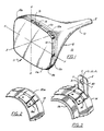
- Fig. 1 is a perspective view of an implosion-banded cathode ray tube having four basal flanges attached to the band and being oriented with reference to X, Y and Z axes;
- Fig. 2 is a close-up perspective view of a corner portion of the band shown in Fig. 1, including the attached basal flange;
- Fig. 3 is a view similar to that of Fig. 2, in which an apertured top plate has been attached to the basal flange at a location to center the aperture at point x₁, y₁, z₁;
- Fig. 4 is a plan view of a shrink band with four basal flanges attached, shown oriented with respect to X and Y axes by coarse and fine locators;
- Fig. 5 is a side view along section A-A of the band of Fig.4, showing one of the basal flanges in association with a set of coarse and fine locators;
- Figs. 6 and 7 are views similar to that of Fig.2 showing two other embodiments of basal flanges;
- Fig. 8 is a section view of a portion of a CRT face plate and associated implosion band;
- Fig. 9 is a perspective view of one embodiment of a two-piece mounting bracket of the invention;
- Fig. 10 is a front elevation view of another embodiment of a two-piece mounting bracket of the invention;
- Fig. 11 is a front elevation view of still another embodiment of a two-piece mounting bracket of the invention; and
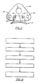
- Fig. 12 is a block flow diagram of one embodiment of the method of the invention.
- Referring now to Fig. 1, there is shown in perspective an implosion-banded
cathode ray tube 10 oriented in space with reference to X, Y, and Z axes. The glass face panel 11, including face 11a and sidewall or skirt 11b, is joined tofunnel 12, having aneck portion 13, by a frit seal 11c, located to the rear ofimplosion band 14.Band 14 is a shrink band, so-called because it is pre-formed, and then expanded by heating to fit around the panel skirt, and finally allowed to cool, thereby shrinking around the skirt to place the panel in mechanical compression. - The band is formed by first cutting a length of steel strip from a roll, straightening end portions of the strip and then butt welding the straightened ends together to form an egg-shaped hoop. This hoop is then passed between rollers which form a shallow longitudinal bend in the hoop. This bend effectively raises the
central portion 80 of theband 14 slightly above the glass surface, to provide clearance for themold match line 81 on skirt 11b, as shown in Fig.8. Bend angle alpha (α) is typically about 5°. - After bending, the hoop is stretched into a rectangular shape corresponding to the outline of the face panel, and the forward edge of the corner portions are rolled over slightly to provide a snug fit with the corners of the face panel. This rolled edge, 82 in Fig.8, is sometimes referred to as an "eyebrow".
- Following stretching,
fishplate 15, an elongated metal plate, is welded onto theband 14 across thebutt weld 16 for added strength, as shown in Fig.1. Next, four basal flanges (three of which, 18a, 18b, and 18c, are shown) are welded to the corner portions ofband 14. - Next, and 14 is dropped onto a set of four
coarse locator blocks lips basal flanges fine locators 41a, 41b, 41c and 41d. Following such engagement, shown by partial section view A-A in Fig. 5, coarse locators 40 swing out of the way, about pivot points indicated as 50 forlocator 40d in Fig.5, to allow the band to drop onto the fine locators, which then position the band accurately in the X-Y plane for subsequent heating. After positioning, the fine locator feed mechanisms are disengaged to allow these locators to float during heating, band expansion, and application. - Following band expansion, the tube is inserted into the band. The band is then allowed to shrink into place on the panel skirt.
- Due to an accumulation of errors from various sources, use of the above-described banding process results in locating the basal flanges on the tube to an accuracy of only about plus or
minus 30 to 70 thousandths of an inch. However, attachment of the basal flanges prior to banding is necessary in order to avoid cracking of the glass under the band during welding of the top plates. - Referring now to Fig.3, after the band has shrunk onto skirt 11b, the tube is oriented in space with reference to X, Y, and Z axes, and top plate or "ear" 30 is welded onto basal flange at a location where the center of
aperture 31 corresponds to point x₁, y₁, z₁. By such a technique, ear may be mounted with an accuracy on the order of plus or minus 10 thousandths of an inch. Alternatively, the ears may be omitted in cases in which other mounting arrangements are contemplated. - The ability to accurately place bracket mounting apertures leads to other advantages, including: greater flexibility in cabinet design due to large permissible variation in Z axis placement of top plates on basal flanges: ability to use the same parts interchangeably on different tube sizes and shapes, leading to reduced inventory; increased allowable tolerances on parts and glass leading to lower tooling and material costs; and ability to inexpensively roughen (e.g., by coining) one or both sides of the top plate, thus avoiding the need for separate lock washers.
- Other embodiments of basal flanges are shown in Figs. 6 and 7. Fig. 6 shows
basal flange 60 having no raised lip. Such an embodiment is suitable for use with conventional tension bands, which bands do not require engagement with separate locating means. Such bands are stretched around the face panel and affixed by a mechanical tensioning or strapping tool. Thus, the basal flange serves only as an attachment surface, not as a holder for band location. - Fig. 7 shows a U-shaped
basal flange 70 attached toband 71. Such an embodiment may be useful where large variations in specifications for location in the Z axis direction are anticipated. - Figs. 9 through 11 show other embodiments of two-piece mounting brackets of the invention. In Fig. 9,
basal flange 90 has two projections from the rear edge of the flange, 90a and 90b, which projections are resistance welded totop plate 91. These projections are advantageous in that in some cases X, Y location is more critical than Z location. - In Fig. 10,
basal flange 99 includesupstanding portion 100 having acentral saddle 100a. This saddle enables placement of the aperture 101a oftop plate 101 closer to the face panel than would otherwise be possible. Attachment, such as by resistance welding, is atlocations spring mounting apertures - In Fig. 11,
upstanding portion 110 of basal flange 111 is located betweenspring mounting apertures top plate 114 byresistance welds - Fig. 12 is a block diagram of the basic steps of the described process.
Claims (12)
Applications Claiming Priority (2)
| Application Number | Priority Date | Filing Date | Title |
|---|---|---|---|
| US902822 | 1986-09-02 | ||
| US06/902,822 US4668993A (en) | 1986-09-02 | 1986-09-02 | Two-piece mounting brackets and method for applying them to cathode ray tubes |
Publications (2)
| Publication Number | Publication Date |
|---|---|
| EP0258946A2 true EP0258946A2 (en) | 1988-03-09 |
| EP0258946A3 EP0258946A3 (en) | 1989-06-14 |
Family
ID=25416451
Family Applications (1)
| Application Number | Title | Priority Date | Filing Date |
|---|---|---|---|
| EP87201646A Withdrawn EP0258946A3 (en) | 1986-09-02 | 1987-08-31 | Two-piece mounting brackets and method for applying them to cathode ray tubes |
Country Status (4)
| Country | Link |
|---|---|
| US (1) | US4668993A (en) |
| EP (1) | EP0258946A3 (en) |
| JP (1) | JPS6369129A (en) |
| KR (1) | KR950011705B1 (en) |
Cited By (1)
| Publication number | Priority date | Publication date | Assignee | Title |
|---|---|---|---|---|
| GB2249866A (en) * | 1990-09-28 | 1992-05-20 | Videocolor Spa | Cathode-ray tube having implosion protection band |
Families Citing this family (5)
| Publication number | Priority date | Publication date | Assignee | Title |
|---|---|---|---|---|
| ATE124572T1 (en) * | 1989-10-02 | 1995-07-15 | Philips Electronics Nv | STRUCTURE OF IMPLOSION PROTECTION TAPES, IMPLOSION PROTECTION TAPE FOR SUCH A STRUCTURE AND IMAGE PLAYBACK TUBE HAVING SUCH AN IMPLOSION PROTECTION TAPE. |
| US5036577A (en) * | 1989-11-30 | 1991-08-06 | Thomson Consumer Electronics, Inc. | Method of forming a shrink fit implosion protection band |
| US5233432A (en) * | 1991-11-04 | 1993-08-03 | Thomson Consumer Electronics | Cathode-ray tube having implosion protection means with a structure and method to facilitate attachment of tube mounting means |
| JP3196273B2 (en) * | 1991-12-26 | 2001-08-06 | ソニー株式会社 | Explosion-proof band and cathode ray tube |
| DE69403095T2 (en) * | 1993-02-03 | 1997-11-13 | Philips Electronics Nv | Anti-implosion band for an electron beam tube |
Family Cites Families (3)
| Publication number | Priority date | Publication date | Assignee | Title |
|---|---|---|---|---|
| US3271516A (en) * | 1962-10-22 | 1966-09-06 | Owens Illinois Inc | Implosion resistant cathode ray tube with integral mounting elements to facilitate installation |
| US3651257A (en) * | 1970-10-19 | 1972-03-21 | Motorola Inc | Mounting bracket for television picture tube |
| US4360837A (en) * | 1980-07-11 | 1982-11-23 | North American Philips Consumer Electronics Corp. | Cathode ray tube support system |
-
1986
- 1986-09-02 US US06/902,822 patent/US4668993A/en not_active Expired - Fee Related
-
1987
- 1987-08-31 EP EP87201646A patent/EP0258946A3/en not_active Withdrawn
- 1987-08-31 KR KR1019870009554A patent/KR950011705B1/en not_active Expired - Lifetime
- 1987-08-31 JP JP62215531A patent/JPS6369129A/en active Pending
Cited By (3)
| Publication number | Priority date | Publication date | Assignee | Title |
|---|---|---|---|---|
| GB2249866A (en) * | 1990-09-28 | 1992-05-20 | Videocolor Spa | Cathode-ray tube having implosion protection band |
| US5241393A (en) * | 1990-09-28 | 1993-08-31 | Videocolor S.P.A. | Cathode-ray tube having implosion protection band |
| GB2249866B (en) * | 1990-09-28 | 1994-08-17 | Videocolor Spa | Cathode-ray tube having implosion protection band |
Also Published As
| Publication number | Publication date |
|---|---|
| US4668993A (en) | 1987-05-26 |
| EP0258946A3 (en) | 1989-06-14 |
| JPS6369129A (en) | 1988-03-29 |
| KR880004535A (en) | 1988-06-07 |
| KR950011705B1 (en) | 1995-10-07 |
Similar Documents
| Publication | Publication Date | Title |
|---|---|---|
| US4668993A (en) | Two-piece mounting brackets and method for applying them to cathode ray tubes | |
| US5057929A (en) | Cathode ray tube having implosion band with raised tabs and method | |
| US5443410A (en) | Getter fixing device for a cathode ray tube | |
| JPH01274343A (en) | Crt tension mask and its reference and support system | |
| US5347367A (en) | Cathode-ray tube having implosion protection means with openings | |
| CA2042789C (en) | Crt with implosion protection means having mounting lug base-accommodating concavities therein | |
| US5036577A (en) | Method of forming a shrink fit implosion protection band | |
| EP0878821A2 (en) | Cathode ray tube with support members for the shadow mask frame | |
| US5064394A (en) | Method of forming a shrinkfit implosion protection band having a concavity therein | |
| US5348506A (en) | Method of assembling a shadow mask and an apparatus for carrying out the same | |
| US6089937A (en) | Cathode-ray tube dividing apparatus and cathode-ray tube dividing method | |
| US5416378A (en) | Color picture tube with iron-nickel alloy shadow mask | |
| JP3433147B2 (en) | Method for welding shadow mask for flat cathode ray tube | |
| US4206534A (en) | Implosion-resistant cathode ray tube and fabricating process | |
| KR0137093Y1 (en) | Strength band structure for cathode ray tube | |
| CN1023041C (en) | Color picture tube having improved shadow mask-frame assembly support | |
| US6573646B2 (en) | Structure for supporting shadow mask in color cathode ray tube | |
| JP3368813B2 (en) | Color picture tube | |
| GB2319887A (en) | Cathode ray tubes | |
| JPH0623148U (en) | Explosion-proof CRT | |
| JP3269744B2 (en) | Color cathode ray tube | |
| JPS6035953Y2 (en) | Explosion-proof cathode ray tube | |
| JP2724531B2 (en) | How to attach a filament shield for fluorescent lamps | |
| EP0881661B1 (en) | Image display apparatus and method of manufacturing the same | |
| KR100189413B1 (en) | A method and a device of coupling frame with mask in crt |
Legal Events
| Date | Code | Title | Description |
|---|---|---|---|
| PUAI | Public reference made under article 153(3) epc to a published international application that has entered the european phase |
Free format text: ORIGINAL CODE: 0009012 |
|
| AK | Designated contracting states |
Kind code of ref document: A2 Designated state(s): DE FR GB IT |
|
| PUAL | Search report despatched |
Free format text: ORIGINAL CODE: 0009013 |
|
| AK | Designated contracting states |
Kind code of ref document: A3 Designated state(s): DE FR GB IT |
|
| 17P | Request for examination filed |
Effective date: 19891204 |
|
| RAP1 | Party data changed (applicant data changed or rights of an application transferred) |
Owner name: NORTH AMERICAN PHILIPS CORPORATION |
|
| 17Q | First examination report despatched |
Effective date: 19900626 |
|
| STAA | Information on the status of an ep patent application or granted ep patent |
Free format text: STATUS: THE APPLICATION IS DEEMED TO BE WITHDRAWN |
|
| 18D | Application deemed to be withdrawn |
Effective date: 19930120 |
|
| RIN1 | Information on inventor provided before grant (corrected) |
Inventor name: HERMANN, KENNETH WILLIAM |