EP0258150B1 - System for measurement of traveling webs - Google Patents
System for measurement of traveling webs Download PDFInfo
- Publication number
- EP0258150B1 EP0258150B1 EP87401942A EP87401942A EP0258150B1 EP 0258150 B1 EP0258150 B1 EP 0258150B1 EP 87401942 A EP87401942 A EP 87401942A EP 87401942 A EP87401942 A EP 87401942A EP 0258150 B1 EP0258150 B1 EP 0258150B1
- Authority
- EP
- European Patent Office
- Prior art keywords
- light
- web
- wavelengths
- ducts
- sheet
- Prior art date
- Legal status (The legal status is an assumption and is not a legal conclusion. Google has not performed a legal analysis and makes no representation as to the accuracy of the status listed.)
- Expired - Lifetime
Links
Images


Classifications
-
- G—PHYSICS
- G01—MEASURING; TESTING
- G01N—INVESTIGATING OR ANALYSING MATERIALS BY DETERMINING THEIR CHEMICAL OR PHYSICAL PROPERTIES
- G01N21/00—Investigating or analysing materials by the use of optical means, i.e. using sub-millimetre waves, infrared, visible or ultraviolet light
- G01N21/17—Systems in which incident light is modified in accordance with the properties of the material investigated
-
- G—PHYSICS
- G01—MEASURING; TESTING
- G01N—INVESTIGATING OR ANALYSING MATERIALS BY DETERMINING THEIR CHEMICAL OR PHYSICAL PROPERTIES
- G01N21/00—Investigating or analysing materials by the use of optical means, i.e. using sub-millimetre waves, infrared, visible or ultraviolet light
- G01N21/84—Systems specially adapted for particular applications
- G01N21/86—Investigating moving sheets
-
- G—PHYSICS
- G01—MEASURING; TESTING
- G01N—INVESTIGATING OR ANALYSING MATERIALS BY DETERMINING THEIR CHEMICAL OR PHYSICAL PROPERTIES
- G01N21/00—Investigating or analysing materials by the use of optical means, i.e. using sub-millimetre waves, infrared, visible or ultraviolet light
- G01N21/01—Arrangements or apparatus for facilitating the optical investigation
- G01N21/15—Preventing contamination of the components of the optical system or obstruction of the light path
- G01N2021/151—Gas blown
-
- G—PHYSICS
- G01—MEASURING; TESTING
- G01N—INVESTIGATING OR ANALYSING MATERIALS BY DETERMINING THEIR CHEMICAL OR PHYSICAL PROPERTIES
- G01N21/00—Investigating or analysing materials by the use of optical means, i.e. using sub-millimetre waves, infrared, visible or ultraviolet light
- G01N21/84—Systems specially adapted for particular applications
- G01N21/86—Investigating moving sheets
- G01N2021/8645—Investigating moving sheets using multidetectors, detector array
-
- G—PHYSICS
- G01—MEASURING; TESTING
- G01N—INVESTIGATING OR ANALYSING MATERIALS BY DETERMINING THEIR CHEMICAL OR PHYSICAL PROPERTIES
- G01N21/00—Investigating or analysing materials by the use of optical means, i.e. using sub-millimetre waves, infrared, visible or ultraviolet light
- G01N21/84—Systems specially adapted for particular applications
- G01N21/86—Investigating moving sheets
- G01N2021/8663—Paper, e.g. gloss, moisture content
Definitions
- the present invention generally relates to a system for measuring properties of traveling webs of fibrous sheet material during manufacture and, more particularly, to a system for providing measurements such as dry basis weight, basis weight, and moisture content of fibrous sheet materials.
- Basis weight is normally defined as the weight per unit area of sheet material and is usually stated in units of grams per square meter.
- Dry basis weight a related measure that is particulary useful during the manufacture of fibrous sheet materials such as paper and cardboard, refers to weight per unit area of sheet material excluding moisture.
- dry basis weight is equivalent to the weight of dry material, primarily fibers, comprising a given area of a paper sheet.
- Moisture content refers to the amount of moisture per unit area of a sheet.
- the amount of absorbed radiation at a particular wave length is a function of the composition of the sheet material; for example, the cellulose content of paper sheet material is indicated by the absorption of infrared light having a wavelength of about 1.5 microns.
- parametric measurements may include basis weight, dry basis weight, moisture content, thickness, and transmissivity.
- on-line parametric measurements are difficult to make accurately.
- on-line measurements in paper-making processes are often problematical because of severe environmental conditions; for example, the environment around a paper-making machine may include a high concentration of wet pulp and a humid atmosphere that contains water droplets and air-borne particles of acids or alkalies. Regardless of such conditions, however, practical on-line measuring devices on sheet-making machines must operate continuously for extended periods and their repair and maintenance must be accomplished without causing substantial down-time to the sheet-making machines.
- scanning gauges in sheet-making operations, such gauges have limitations.
- the moving parts in scanning gauges can cause repair and maintenance problems.
- scanning gauges that require relatively long periods to make successive measurements are not optimal for control purposes that require a relatively large number of measurements over relatively short periods.
- conventional scanning gauges for detecting the basis weight and moisture content of fibrous sheet materials normally require about thirty seconds to obtain a series of measurements over a traveling sheet in the cross direction. (A series of such measurements in the cross-direction are said to provide a "profile" of the sheet.)
- U.S. Patent 3,806,730 suggests a measuring device that includes a set of tubes mounted to distribute light onto the surface of a moving web in the cross direction.
- the tubes are rectangular aluminium pipes that have bright interior surfaces to carry light.
- a set of similar tubes is positioned to receive and detect light transmitted through the web.
- the device described in the patent is said to be useful for measuring parameters such as basis weight and moisture content of paper sheet materials.
- document GB-A-2 015 724 shows a system for detecting holes in moving webs.
- This system includes a row of individually mutually sideways displaced stepped mirror strips, in combination with a scanning device over the individual mirrors of each strip, to generate a scanning light curtain directed at the surface of the web.
- an object and advantage of the present invention is to provide an improved system to detect properties of traveling webs of sheet material for use with a supervisory control system for a paper-making machine.
- an object of the present invention is to provide an improved system for providing parametric measurements of properties, such as dry basis weight and moisture content, across profiles of traveling webs of sheet material without scanning the webs.
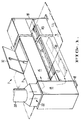
- Figure 1 is a pictorial view of the exterior of a housing of a machine that operates according to the present invention. In this drawing some internal components of the machine are generally indicated by dashed lines.
- FIGURE 2 is a generally schematic diagram of a machine that operates according to the present invention. This diagram is generally oriented as a vertical cross-section taken lengthwise through the machine of FIGURE 1.
- FIGURE 3 is a pictorial view, drawn to an expanded scale for purposes of illustration, of certain components of the machine of FIGURE 1.
- FIGURE 4 is a pictorial view of one embodiment of an array of mirrors for use in the machine of FIGURE 1.
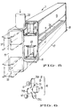
- FIGURE 5 is a pictorial view, partially cutaway, showing certain internal components of the machine of FIGURE 1. In this drawing, components that are in displaced positions are shown by dashed lines.
- FIGURE 6 is an exploded pictorial view of components comprising a light source assembly for use in the machine of FIGURE 1.
- FIGURE 7 is a detailed view, drawn to an enlarged scale for purposes of explanation, of a light detection assembly for use in the machine of FIGURE 1.
- FIGURE 8 is a functional diagram of an electronic system for processing signals obtained by the machine of FIGURE 1.
- FIGURE 1 shows a machine, generally indicated by the numeral 7, for providing parametric measurements of a web 9 of sheet material traveling horizontally through the machine in the direction indicated by the arrow.
- a particular feature of machine 7 is that measurements of parameters of web 9 such as basis weight, dry basis weight and moisture content can be made for a full profile of web 9 without scanning the web.
- Machine 7 generally includes a housing that protectively isolates measurement instruments and components in ducts 15 and 17.
- ducts 15 and 17 are supported at their opposite ends by upstanding stanchions 18.
- ducts 15 and 17 range in length from about 100 inches to about 400 inches and are spaced apart vertically by a distance of about eight inches to allow clearance for web 9 to travel between the ducts.
- machine 7 can be installed on a paper-making machine at any convenient location between a first press section and a windup roll, the housing of the machine is particularly adapted for installation near the first press section.
- ducts 15 and 17 are connected in gas flow communication with a cross duct 19, and pressurized air is provided to the ducts via inlet duct 20.
- Thermostatic controls 21 and heaters 22, shown schematically in FIGURE 2 are provided in housing 11 to provide the heated air at temperatures sufficiently above dew point temperature (usually about 100°F) to prevent condensation from forming on the surfaces of ducts 15 and 17.
- thermostatic control 21 operates in response to outputs from a conventional thermistor 21A
- heater 22 is a conventional electric heater proportionally controlled by thermistor 21A.
- ducts 15 and 17 have transparent walls 23 and 25, respectively, that provide line-of-sight optical communication between the interiors of the ducts.
- both the lower horizontal wall 23 of duct 15 and the upper horizontal wall 25 of duct 17 are transparent so that the interior of one of the ducts can be viewed from the interior of the other duct in the absence of web 9.
- Such line-of-sight communication between the ducts is indicated schematically by the vertical arrows in FIGURE 2.
- transparent walls 23 and 25 each comprise a single pane of glass, but a series of separate windows formed of glass or other transparent materials can be utilized. In practice, transparent walls 23 and 25 are about three inches wide.
- FIGURE 3 A suitable particulate-removal device to prevent such accumulations is illustrated in FIGURE 3 in conjunction with transparent wall 25. It should be understood that a similar particulate-removal device is provided to keep transparent wall 23 free from accumulations of particles.
- the particulate-removal device in FIGURE 3 produces air flows, indicated by the curved arrows, that continuously sweep the exterior surfaces of transparent wall 25.
- the particulate removal means includes open-ended channels 29 formed at spaced-apart locations in an elongated frame member 30 that supports one side of wall 25.
- channels 29 are oriented to direct flows of pressurized air across the exterior surface of wall 25 as indicated.
- the interior open ends of channels 29 are in gas-flow communication with the interior of duct 17 to receive air flow driven by pressurized air carried by the duct.
- channels 29 are spaced along the full length of transparent walls 23 and 25, and transparent walls 23 and 25 are slightly canted from horizontal to promote water drainage from their surfaces.
- doors 32 are mounted along the length of ducts 15 to provide access to the interior of the duct.
- sliding tray-like mechanisms 33 are mounted to extend lengthwise within upper and lower ducts 15 and 17 to carry the measurement instruments and components.
- the tray-like mechanisms 33 each have a box-like configuration and include runners, or the like to guide the tray-like mechanisms within ducts 15 and 17.
- the ends of duct 15 and 17 are opened and tray-like mechanisms 33 are slidably removed as indicated by dashed lines in FIGURE 5.
- FIGURES 2, 4 and 7 The components of machine 7 for providing optical measurements of a traveling web of sheet material are best illustrated in FIGURES 2, 4 and 7.
- the optical components include a light source 41 mounted at one end of duct 17, a mirror array 43 mounted along the length of duct 17 to reflect source light through transparent wall 25 along substantially the entire cross-directional extent of web 9, and sets 45 of light detection devices mounted in duct 15 to receive light transmitted through transparent wall 23.
- light source 41 is positioned to direct at least two beams of substantially collimated light through duct 17 generally parallel to the longitudinal centerline of the duct, and mirror array 43 is stationarily mounted within duct 17 to receive and decompose the collimated beams to provide parallel rays directed upwardly through transparent wall 25 generally perpendicular to the surface of web 9 along substantially its entire width.
- the sets 45 of light detection devices are mounted in series, as partially shown in FIGURE 7, with the sets 45 spaced apart from each other about every three to six inches across substantially the entire width of web 9.
- mirror array 43 comprises slanting mirror sections 44 mounted on a generally planar base such that, in profile, the mirror sections 44 have a continuous saw-tooth-like configuration.
- the angle of each mirror section 44 is about forty-three degrees relative to the base of the array and, in assembled condition, the planar base is mounted in duct 17 at a slight angle from horizontal, usually about two degrees.
- mirror arrays 43 extend as a continuous ramp along the length of duct 17 in the path of light beams from source 41 and for the angles mentioned previously, the individual mirror sections 44 then each slant at an angle of about forty-five degrees from horizontal.
- the collimated beams of light that are generally horizontally incident on the staggered slanting sections 44 along the length of mirror array 43 are decomposed into parallel rays directed substantially vertically.
- web 9 is wider than about eighteen feet, two mirror arrays are utilized and a light source is located at each end of duct 17.
- light source 41 includes two illuminating devices 61 fixedly mounted at the end of duct 17.
- illuminating devices 61 are conventional incandescent lamps and each includes a parabolic reflector member that forms a collimated beam of generally parallel rays emitted through an appropriate lens mounted at the mouth of the reflector.
- illuminating devices 61 are incandescent lamps that emit a broad band of visible and infrared light including light within the wavelength band between 1.3 and 2.1 microns.
- FIGURE 6 further shows a mechanism for modulating, or chopping, the beams of light from illuminating devices 61.
- the modulating mechanism includes a rotor member 73 having three symmetrical vanes 75A, 75B, and 75C that radially extend at about 120° intervals from the center of rotation of the rotor member.
- rotor member 73 is rotatably driven by motor 59 so that vanes 75A, 75B and 75C simultaneously block, or unblock, light from illuminating lamps 61 depending upon the angular position of the vanes.
- a stationarilymounted position detector 81 can be provided to detect the rotational position of vanes 75A, 75B and 75C.
- Position detector 81 can, for example, be a light-emitting diode combined with a phototransistor (see FIGURE 8) mounted to detect passage of light through a small hole in one of the rotor vanes at a predetermined position. Output signals from position detector 81 are used to provide timing and synchronization as will be later explained in detail.
- each set 45 of the light detection devices includes an assembly of components for collimating, filtering and sensing light rays that have been transmitted through web 9 generally perpendicular to the web surface.
- the collimating components of the light detection devices include converging lenses 47 and 49, and aperture plates 48.
- aperture plates 48 are stationarily mounted generally at the focal points of lenses 47; the second converging lenses 49 are mounted beyond the aperture plate 48 by distances approximately equal to the focal length of lenses 49.
- Lenses 47 and 49 can be, for example, Fresnel-type lenses.
- each set 45 of light detection devices in FIGURE 1 includes components for filtering and sensing light.
- sets of those filtering and sensing components are generally indicated by bracket 50 and each individual set 50 includes four optical bandpass filters 53A-D and four photoelectric transducers 54A-D, respectively.
- Bandpass filters 53A-D differ from each other in terms of the bands of wavelengths of light that they pass. In fibrous sheet-making operations such as papermaking, for example, the infrared spectrum is usually of primary interest.
- bandpass filter 53A is selected to pass light in a narrow band of wavelengths about a mean value of 1.5 microns
- bandpass filter 53B is selected to pass light in a narrow band of wavelengths about a mean value of 1.3 microns
- bandpass filter 53C is selected to pass light in a narrow band of wavelengths about a mean value of about 1.9 microns
- bandpass filter 53D is selected to pass light in a narrow band of wavelengths about a mean value of 1.8 microns.
- the wavelengths of light passed by bandpass filters 53A and 53C will be called the “measurement” wavelengths and the wavelengths passed by bandpass filters 53B and 53D will be called the “reference” wavelengths.
- the measurement wavelengths are selected for preferential absorbtion by the sheet material of web 9 and the reference wavelengths are selected for less substantial absorbtion.
- one measurement wavelength is normally chosen for specific absorptions by cellulose fibers and one reference wavelength is chosen to be near, but outside, the resonant absorption band of cellulose.
- the photoelectric transducers 54A-D in the sets 45 of light detection devices in FIGURE 7 are substantially identical.
- the transducers can, for example, be of the type made from lead sulfide.
- transducers 54A are mounted to bandpass filters 53A such that all light reaching the transducers passes through the filters.
- transducers 54B are mounted to bandpass filters 53B such that all light reaching the transducer passes through the bandpass filters.
- the pairs of transducers and filters 53C-54C and 53D-54D are similarly associated.
- transducers 54A and 54C will receive light only at the measurement wavelength; likewise, in the case where bandpass filters 53B and 53D pass light at the reference wavelengths, transducers 54B and 54D will receive light only at the reference wavelengths.
- the pairs of bandpass filters and photoelectric transducers are shown to be mounted side by side in the cross direction in FIGURES 2 and 7; however, those pairs could be grouped in other configurations.
- diffusers 56 are mounted across apertures 58 in aperture plate 48 to provide mixing of light rays passed through apertures 58.
- diffusers 56 are usually thin sheets formed of Teflon.
- diffusing lenses can be used to mix light rays passing through apertures 58.
- FIGURE 8 a system is schematically shown for processing electrical signals produced by the groups of photoelectric transducers 54A-54D.
- the purpose of the electronic system is to provide output signals indicative of optical properties of examined profiles of traveling webs.
- the system in FIGURE 8 includes position detector 81 that provides output signals that are indicative of the rotational position of rotor 73.
- the output signals from position detector 81 are conveyed to a pulse converter 82 that converts the signals into square-wave signals to facilitate synchronization of subsequent processing steps.
- the system of FIGURE 8 further includes a photoelectric transducer 54 connected to a conventional preamplifier 83 that amplifies the electrical output signals from the transducer.
- Transducer 54 should be understood to be representative of any one of the transducers 54A-D described above.
- a demodulator 85 using the square-wave position signals from converter 82 for synchronization purposes, is connected to demodulate the output signals for preamplifier 83 and, thereby, to provide direct current signals having amplitudes proportional to the intensity of light received by photoelectric transducer 54.
- demodulated signals derived from one of the transducers 54 are multiplexed with output signals from other of the transducers 54 (not shown) by a multiplexer 87.
- the multiplexed signals are converted to digital form by a conventional analog-to-digital converter 89 for further processing.
- the electronic components i.e., pulse converter 82, preamplifier 83, demodulator 85, multiplexer 87, and analog-to-digital converter 89
- the analog signals from the sets of transducers 54A-D are substantially undisturbed by extraneous sources of light.
- the air blown into ducts 15 and 17 provides sufficient positive pressure to create air flows that sweep the surfaces of transparent walls 23 and 25, as shown in FIGURE 3, to prevent accumulation of particulates on those walls. Still further, the air keeps mirror array 43 free of dust by providing sufficient pressurization to prevent dust particles from entering ducts 15 and 17.
- rotor 73 is rotatably driven to modulate the emitted light beams from illuminating devices 61.
- the beams extend along duct 17 and are decomposed and reflected by the staggered slanting section 44 of mirror array 43.
- the decomposed beams form parallel rays that are directed upward through transparent wall 25 generally perpendicular to the surface of web 9 along the length of mirror array 43.
- one effect of directing parallel rays perpendicularly to web 9 is that optical measurements of the web's transmissive properties can be substantially independent of its vertical location between ducts 15 and 17.
- the quantity of light detected by photoelectric detectors 54 could vary depending upon the elevation of the web surface. Such variations could be caused, for example, by fluttering of the web and, if present, would complicate accurate determination of the web's optical properties.
- DBW AO + A1*1n(MES1) - A2*1n(REF1) + A3*1n(MES2) - A4*1n(REF2).
- BW B0 + B1*1n(MES1) - B2*1n(REF1) + B3*1n(MES2) - B4*1n(REF2).
- MC C0 +C1*1n(MES1) - C2*1n(REF1) + C3*1n(MES2) - C4*1n(REF2).
- Moisture 100*MC/BW.
- the signal determined when web 9 is present may be referred to as an "on-sheet” signal, and the signal determined when web 9 is not present may be referred to as an "off-sheet” signal.
- MES1 is the onsheet signal at the first measurement wavelength divided by the off-sheet signal at the same wavelength.
- REF1 is the on-sheet signal level at the first reference wavelength divided by the off-sheet signal level at the same wavelength.
- MES2 is the on-sheet signal level at the second measurement wavelength divided by the off-sheet signal level at the same wavelength.
- REF2 is the on-sheet signal level at the second reference wavelength divided by the off-sheet signal level at the same wavelength.
- the coefficients A0, A1, A2, A3 and A4 are constants relating to the dry basis weight. Normally, coefficients A1 and A2 are both positive in sign and are approximately equal in magnitude, and coefficients A3 and A4 are relatively smaller in magnitude than A1 and A2.
- the coefficients B0, B1, B2, B3 and B4 are calibration constants relating to basis weight. Coefficients B1 and B2 are usually both positive in sign and approximately equal in magnitude, and coefficients B3 and B4 are relatively smaller in magnitude than B1 and B2.
- the coefficients C0, C1, C2, C3 and C4 are calibration constants for determination of moisture content. Normally, coefficients C3 and C4 are both positive in sign and approximately equal in magnitude, while C1 and C2 are relatively smaller in magnitude than C3 and C4.
- the wavelengths for the MES1 measurements are chosen to be sensitive primarily to the dry basis weight of the paper. In practice, such wavelengths include not only a narrow band of wavelengths about a mean value of 1.5 microns, but also a narrow band of wavelengths about a mean value of 2.1 microns.
- the REF1 wavelengths are usually chosen at a narrow band of wavelengths about a mean value of 1.3 or 1.8 microns and are used to correct the basis weight measurement for other properties of the paper as well as for effects due to particulates that may fall on the optical surfaces in the system.
- the MES2 wavelengths are usually chosen at a narrow band of wavelengths about a mean value of 1.9 microns and are sensitive primarily to the water content of paper.
- the REF2 wavelengths are chosen at a narrow band of wavelengths about a mean value of 1.8 microns and are used to correct the moisture measurements for other properties of paper and for any contaminants on the exposed optical surfaces.
- the above-described system permits measurements to be taken simultaneously across the full width of web 9. This feature distinguishes the system from scanning type devices that operate to sequentially take measurement across a web.
- One result of providing non-scanning sensors is that the sequence of readouts of the entire line of detectors can be relatively more rapid than with scanning-type sensors.
- the non-scanning sensors described above can provide a full profile of sheet 9 in five seconds or less. The capability to quickly perform profile measurements allows rapid actuators to be used and provides much shorter machine control cycles. This is important during startups, grade changes and upsets, but also can reduce machine direction variations in steady-state operation and reduces sensitivity to periodic instabilities.
- dry basis weight can be expressed in terms of two detected wavelengths as follows: wherein: DBW is dry basis weight of the inspected area of sheet material; A, B and C are constants; “1n” indicates the natural logarithmic function; “REF on sheet” is the output of a reference detector when sheet material is present in the gap between ducts 15 and 17; “REF no sheet” is the output of a reference detector in the absence of sheet material in the gap between ducts 15 and 17: “MEAS on sheet” is the output of a measurement detector when sheet material is present in the gap between ducts 15 and 17; and “MEAS no sheet” is the output of a measurement detector when sheet material is absent from the gap between ducts 15 and 17.
- machine 7 may include light collimating devices, such as so-called honeycomb filters, to provide additional collimation of light passing through transparent walls 23 and 25; such filters can further minimize variations due to flutter or other elevation change of web 9 within the vertical gap between ducts 15 and 17.
- light collimating devices such as so-called honeycomb filters
- illuminating devices 61 can be mounted to direct beams of light perpendicular to the side of housing 11 with deflecting mirrors arranged to deflect the beams and direct them generally parallel to the centerline of duct 17 toward mirror arrays 43.
- modulating devices other than the illustrated rotor 73 can be employed to chop the output light from lamps 61.
- the modulating devices can include optical filters such that the modulated light is emitted sequentially at different wavelengths; for example, optical filters at the modulating device could provide light filtered at a narrow band of wavelengths about a mean value of 1.5 microns, followed by light filtered at a narrow band of wavelengths about a mean value of 1.3 microns, then at 1.9 microns and at 1.8 microns.
- the sets 45 of light detection devices could include only a single optical bandpass filter.
Landscapes
- Physics & Mathematics (AREA)
- Health & Medical Sciences (AREA)
- Life Sciences & Earth Sciences (AREA)
- Chemical & Material Sciences (AREA)
- Analytical Chemistry (AREA)
- Biochemistry (AREA)
- General Health & Medical Sciences (AREA)
- General Physics & Mathematics (AREA)
- Immunology (AREA)
- Pathology (AREA)
- Investigating Or Analysing Materials By Optical Means (AREA)
Description
- The present invention generally relates to a system for measuring properties of traveling webs of fibrous sheet material during manufacture and, more particularly, to a system for providing measurements such as dry basis weight, basis weight, and moisture content of fibrous sheet materials.
- In the manufacture of sheet materials, important parameters for process and quality control include basis weight and moisture content. Basis weight is normally defined as the weight per unit area of sheet material and is usually stated in units of grams per square meter. Dry basis weight, a related measure that is particulary useful during the manufacture of fibrous sheet materials such as paper and cardboard, refers to weight per unit area of sheet material excluding moisture. In the art of paper-making, dry basis weight is equivalent to the weight of dry material, primarily fibers, comprising a given area of a paper sheet. Moisture content refers to the amount of moisture per unit area of a sheet. These parameters are related by the fact that, for a given area of a sheet, basis weight minus moisture content equals dry basis weight.
- It is well known that dry basis weight can be determined by laboratory tests but that such tests have several inherent drawbacks. One shortcoming of laboratory tests is that substantial time is required for sample acquisition and analysis; during that time, substantial quantities of sheet material may be produced and production conditions may change sufficiently that the laboratory test results, when available, may no longer be representative of the conditions of the manufacturing process or product. Another drawback of laboratory tests is that samples obtained for testing may not completely represent sheet material that has been produced; this is because samples are often obtained only at the end of a sheet roll and, therefore, may not be representative of paper quality at intermediate locations along the roll.
- To detect the composition of sheet materials, it is known to direct a beam of light or other radiation of known wavelength against a surface of a given area of sheet material and to measure the radiation absorbed by the sheet. Generally speaking, the amount of absorbed radiation at a particular wave length is a function of the composition of the sheet material; for example, the cellulose content of paper sheet material is indicated by the absorption of infrared light having a wavelength of about 1.5 microns.
- Various devices have been proposed for making parametric measurements of properties of traveling webs of sheet material on-line. The term "on-line" in this art refers to measurements that are made on a sheet-making machine while the machine is operating. The phrase "parametric measurements" as used herein refers to measurements of physical properties whose values determine characteristics and qualities of the sheet material. Thus, parametric measurements of paper and similar fibrous sheet materials may include basis weight, dry basis weight, moisture content, thickness, and transmissivity.
- In paper-making processes, on-line parametric measurements are difficult to make accurately. The difficulties arise, in part, because modern paper-making machines are large and operate at high speeds. For example, some conventional paper-making machines produce sheets which are 100 to 400 inches wide at the rate of about 20 to 100 feet per second. Furthermore, on-line measurements in paper-making processes are often problematical because of severe environmental conditions; for example, the environment around a paper-making machine may include a high concentration of wet pulp and a humid atmosphere that contains water droplets and air-borne particles of acids or alkalies. Regardless of such conditions, however, practical on-line measuring devices on sheet-making machines must operate continuously for extended periods and their repair and maintenance must be accomplished without causing substantial down-time to the sheet-making machines.
- To provide on-line parametric measurements of paper and other fibrous sheet materials, workers in the art have proposed various sensors that periodically traverse or "scan" traveling webs of sheet material in the cross-direction. (In the sheet-making art, the direction of sheet travel is known as the "machine direction" and the direction across a sheet that is perpendicular to the machine direction is known as the "cross direction"). For example, U.S. Patents 3,641,349; 3,681,595; 3,757,-122; and 3,886,036 assigned to Measurex Corporation discuss basis weight gauges of the scanning type. Also, U.S. Patent 4,289,964, assigned to Intec Corporation, suggests that beta ray gauges can scan slowly across a traveling web in the cross direction to determine basis weight. Further, the patent to Intec suggests that beta ray gauges can be augmented with laser, infrared, or ultraviolet light sensors to indicate transmissive qualities across the web.
- Despite numerous advantages of scanning gauges in sheet-making operations, such gauges have limitations. For example, the moving parts in scanning gauges can cause repair and maintenance problems. Also, scanning gauges that require relatively long periods to make successive measurements are not optimal for control purposes that require a relatively large number of measurements over relatively short periods. For instance, conventional scanning gauges for detecting the basis weight and moisture content of fibrous sheet materials normally require about thirty seconds to obtain a series of measurements over a traveling sheet in the cross direction. (A series of such measurements in the cross-direction are said to provide a "profile" of the sheet.)
- In view of the limitations of scanning devices, it has been proposed to mount a plurality of fixed sensors to detect parameters at locations distributed along the cross-direction of a traveling web of fibrous sheet material. In particular, U.S. Patent 3,806,730 suggests a measuring device that includes a set of tubes mounted to distribute light onto the surface of a moving web in the cross direction. According to the patent, the tubes are rectangular aluminium pipes that have bright interior surfaces to carry light. A set of similar tubes is positioned to receive and detect light transmitted through the web. The device described in the patent is said to be useful for measuring parameters such as basis weight and moisture content of paper sheet materials.
- It has also been proposed, in document US-A-4 577 104, to use a source which directs into the paper sheet two sets of infrared radiation wavelengths. The radiations are detected by a detector which is part of a data acquisition system. This document forms the basis for the preamble of
claim 1. - In document US-A-4 300 049, it has been proposed to utilise a radiation source providing alternatively radiations having two distinct wavelengths, thanks to the rotation of a filter wheel. This radiation source is located within a source housing, facing a detector housing containing two detectors.
- Finally, document GB-A-2 015 724 shows a system for detecting holes in moving webs. This system includes a row of individually mutually sideways displaced stepped mirror strips, in combination with a scanning device over the individual mirrors of each strip, to generate a scanning light curtain directed at the surface of the web.
- Generally speaking, an object and advantage of the present invention is to provide an improved system to detect properties of traveling webs of sheet material for use with a supervisory control system for a paper-making machine.
- More particularly, an object of the present invention is to provide an improved system for providing parametric measurements of properties, such as dry basis weight and moisture content, across profiles of traveling webs of sheet material without scanning the webs.
- According to the invention, these objects are reached thanks to a system as defined in
claim 1. - Figure 1 is a pictorial view of the exterior of a housing of a machine that operates according to the present invention. In this drawing some internal components of the machine are generally indicated by dashed lines.
- FIGURE 2 is a generally schematic diagram of a machine that operates according to the present invention. This diagram is generally oriented as a vertical cross-section taken lengthwise through the machine of FIGURE 1.
- FIGURE 3 is a pictorial view, drawn to an expanded scale for purposes of illustration, of certain components of the machine of FIGURE 1.
- FIGURE 4 is a pictorial view of one embodiment of an array of mirrors for use in the machine of FIGURE 1.
- FIGURE 5 is a pictorial view, partially cutaway, showing certain internal components of the machine of FIGURE 1. In this drawing, components that are in displaced positions are shown by dashed lines.
- FIGURE 6 is an exploded pictorial view of components comprising a light source assembly for use in the machine of FIGURE 1.
- FIGURE 7 is a detailed view, drawn to an enlarged scale for purposes of explanation, of a light detection assembly for use in the machine of FIGURE 1.
- FIGURE 8 is a functional diagram of an electronic system for processing signals obtained by the machine of FIGURE 1.
- FIGURE 1 shows a machine, generally indicated by the
numeral 7, for providing parametric measurements of aweb 9 of sheet material traveling horizontally through the machine in the direction indicated by the arrow. A particular feature ofmachine 7 is that measurements of parameters ofweb 9 such as basis weight, dry basis weight and moisture content can be made for a full profile ofweb 9 without scanning the web.Machine 7 generally includes a housing that protectively isolates measurement instruments and components inducts ducts upstanding stanchions 18. In typical installations,ducts web 9 to travel between the ducts. Althoughmachine 7 can be installed on a paper-making machine at any convenient location between a first press section and a windup roll, the housing of the machine is particularly adapted for installation near the first press section. - In practice, it is preferred that heated air be continuously blown into
ducts machine 7 in FIGURES 1,2 and 5,ducts cross duct 19, and pressurized air is provided to the ducts viainlet duct 20. Thermostatic controls 21 andheaters 22, shown schematically in FIGURE 2, are provided in housing 11 to provide the heated air at temperatures sufficiently above dew point temperature (usually about 100°F) to prevent condensation from forming on the surfaces ofducts conventional thermistor 21A, andheater 22 is a conventional electric heater proportionally controlled bythermistor 21A. - As best shown in FIGURE 2,
ducts transparent walls horizontal wall 23 ofduct 15 and the upperhorizontal wall 25 ofduct 17 are transparent so that the interior of one of the ducts can be viewed from the interior of the other duct in the absence ofweb 9. Such line-of-sight communication between the ducts is indicated schematically by the vertical arrows in FIGURE 2. In the preferred embodiment,transparent walls transparent walls - For practical use of
machine 7 in a paper-producing environment,transparent walls transparent wall 25. It should be understood that a similar particulate-removal device is provided to keeptransparent wall 23 free from accumulations of particles. Generally speaking, the particulate-removal device in FIGURE 3 produces air flows, indicated by the curved arrows, that continuously sweep the exterior surfaces oftransparent wall 25. More particularly, the particulate removal means includes open-endedchannels 29 formed at spaced-apart locations in anelongated frame member 30 that supports one side ofwall 25. The exterior open ends ofchannels 29 are oriented to direct flows of pressurized air across the exterior surface ofwall 25 as indicated. The interior open ends ofchannels 29 are in gas-flow communication with the interior ofduct 17 to receive air flow driven by pressurized air carried by the duct. Preferably,channels 29 are spaced along the full length oftransparent walls transparent walls - Further for practical use of
machine 7 in a paper-producing environment, convenient access must be provided to its components for repair and maintenance. Thus, in the embodiment of FIGURE 1,doors 32 are mounted along the length ofducts 15 to provide access to the interior of the duct. Additionally, in the embodiment in FIGURE 5, sliding tray-like mechanisms 33 are mounted to extend lengthwise within upper andlower ducts like mechanisms 33 each have a box-like configuration and include runners, or the like to guide the tray-like mechanisms withinducts duct like mechanisms 33 are slidably removed as indicated by dashed lines in FIGURE 5. - The components of
machine 7 for providing optical measurements of a traveling web of sheet material are best illustrated in FIGURES 2, 4 and 7. Referring first to FIGURE 2, the optical components include alight source 41 mounted at one end ofduct 17, amirror array 43 mounted along the length ofduct 17 to reflect source light throughtransparent wall 25 along substantially the entire cross-directional extent ofweb 9, and sets 45 of light detection devices mounted induct 15 to receive light transmitted throughtransparent wall 23. In practice,light source 41 is positioned to direct at least two beams of substantially collimated light throughduct 17 generally parallel to the longitudinal centerline of the duct, andmirror array 43 is stationarily mounted withinduct 17 to receive and decompose the collimated beams to provide parallel rays directed upwardly throughtransparent wall 25 generally perpendicular to the surface ofweb 9 along substantially its entire width. Induct 15, thesets 45 of light detection devices are mounted in series, as partially shown in FIGURE 7, with thesets 45 spaced apart from each other about every three to six inches across substantially the entire width ofweb 9. - One embodiment of
mirror array 43 is shown in FIGURE 4. In this embodiment,mirror array 43 comprises slantingmirror sections 44 mounted on a generally planar base such that, in profile, themirror sections 44 have a continuous saw-tooth-like configuration. In practice, the angle of eachmirror section 44 is about forty-three degrees relative to the base of the array and, in assembled condition, the planar base is mounted induct 17 at a slight angle from horizontal, usually about two degrees. Thus, in installed condition,mirror arrays 43 extend as a continuous ramp along the length ofduct 17 in the path of light beams fromsource 41 and for the angles mentioned previously, theindividual mirror sections 44 then each slant at an angle of about forty-five degrees from horizontal. As a result of this structural relationship, as shown in FIGURES 1 and 2, the collimated beams of light that are generally horizontally incident on thestaggered slanting sections 44 along the length ofmirror array 43 are decomposed into parallel rays directed substantially vertically. In practice, ifweb 9 is wider than about eighteen feet, two mirror arrays are utilized and a light source is located at each end ofduct 17. - In FIGURE 6, an assembly comprising a preferred embodiment of
light source 41 is shown. In this embodiment,light source 41 includes two illuminatingdevices 61 fixedly mounted at the end ofduct 17. In practice, illuminatingdevices 61 are conventional incandescent lamps and each includes a parabolic reflector member that forms a collimated beam of generally parallel rays emitted through an appropriate lens mounted at the mouth of the reflector. Preferably, illuminatingdevices 61 are incandescent lamps that emit a broad band of visible and infrared light including light within the wavelength band between 1.3 and 2.1 microns. - FIGURE 6 further shows a mechanism for modulating, or chopping, the beams of light from illuminating
devices 61. In the illustrated embodiment, the modulating mechanism includes arotor member 73 having threesymmetrical vanes 75A, 75B, and 75C that radially extend at about 120° intervals from the center of rotation of the rotor member. Inmachine 7,rotor member 73 is rotatably driven by motor 59 so thatvanes 75A, 75B and 75C simultaneously block, or unblock, light from illuminatinglamps 61 depending upon the angular position of the vanes. - As also shown in FIGURE 6, a
stationarilymounted position detector 81 can be provided to detect the rotational position ofvanes 75A, 75B and 75C.Position detector 81 can, for example, be a light-emitting diode combined with a phototransistor (see FIGURE 8) mounted to detect passage of light through a small hole in one of the rotor vanes at a predetermined position. Output signals fromposition detector 81 are used to provide timing and synchronization as will be later explained in detail. - Reference is now be made to FIGURE 7 which shows that each set 45 of the light detection devices includes an assembly of components for collimating, filtering and sensing light rays that have been transmitted through
web 9 generally perpendicular to the web surface. In the preferred embodiment, the collimating components of the light detection devices include converginglenses aperture plates 48. In the detection assemblies,aperture plates 48 are stationarily mounted generally at the focal points oflenses 47; the second converginglenses 49 are mounted beyond theaperture plate 48 by distances approximately equal to the focal length oflenses 49.Lenses - As mentioned above, each set 45 of light detection devices in FIGURE 1 includes components for filtering and sensing light. In FIGURE 7, sets of those filtering and sensing components are generally indicated by
bracket 50 and each individual set 50 includes four optical bandpass filters 53A-D and fourphotoelectric transducers 54A-D, respectively. Bandpass filters 53A-D differ from each other in terms of the bands of wavelengths of light that they pass. In fibrous sheet-making operations such as papermaking, for example, the infrared spectrum is usually of primary interest. Specifically, for paper-making processes, bandpass filter 53A is selected to pass light in a narrow band of wavelengths about a mean value of 1.5 microns,bandpass filter 53B is selected to pass light in a narrow band of wavelengths about a mean value of 1.3 microns,bandpass filter 53C is selected to pass light in a narrow band of wavelengths about a mean value of about 1.9 microns, and bandpass filter 53D is selected to pass light in a narrow band of wavelengths about a mean value of 1.8 microns. For convenience, such values as well as alternative values are summarized in the table below.
- In the discussion that follows, the wavelengths of light passed by
bandpass filters 53A and 53C will be called the "measurement" wavelengths and the wavelengths passed bybandpass filters 53B and 53D will be called the "reference" wavelengths. In practice, the measurement wavelengths are selected for preferential absorbtion by the sheet material ofweb 9 and the reference wavelengths are selected for less substantial absorbtion. In cases whereweb 9 comprises paper sheet material, for example, one measurement wavelength is normally chosen for specific absorptions by cellulose fibers and one reference wavelength is chosen to be near, but outside, the resonant absorption band of cellulose. - The
photoelectric transducers 54A-D in thesets 45 of light detection devices in FIGURE 7 are substantially identical. The transducers can, for example, be of the type made from lead sulfide. In assembled condition,transducers 54A are mounted to bandpass filters 53A such that all light reaching the transducers passes through the filters. Likewise,transducers 54B are mounted tobandpass filters 53B such that all light reaching the transducer passes through the bandpass filters. The pairs of transducers and filters 53C-54C and 53D-54D are similarly associated. Thus, in the case wherebandpass filters 53A and 53C pass light at the measurement wavelengths,transducers bandpass filters 53B and 53D pass light at the reference wavelengths,transducers - In the preferred embodiment of the sets of
light detection devices 45, shown in FIGURE 7,diffusers 56 are mounted acrossapertures 58 inaperture plate 48 to provide mixing of light rays passed throughapertures 58. In practice,diffusers 56 are usually thin sheets formed of Teflon. Alternatively, diffusing lenses can be used to mix light rays passing throughapertures 58. - Referring now to FIGURE 8, a system is schematically shown for processing electrical signals produced by the groups of
photoelectric transducers 54A-54D. The purpose of the electronic system is to provide output signals indicative of optical properties of examined profiles of traveling webs. The system in FIGURE 8 includesposition detector 81 that provides output signals that are indicative of the rotational position ofrotor 73. In the illustrated system, the output signals fromposition detector 81 are conveyed to apulse converter 82 that converts the signals into square-wave signals to facilitate synchronization of subsequent processing steps. - The system of FIGURE 8 further includes a
photoelectric transducer 54 connected to aconventional preamplifier 83 that amplifies the electrical output signals from the transducer.Transducer 54 should be understood to be representative of any one of thetransducers 54A-D described above. Ademodulator 85, using the square-wave position signals fromconverter 82 for synchronization purposes, is connected to demodulate the output signals forpreamplifier 83 and, thereby, to provide direct current signals having amplitudes proportional to the intensity of light received byphotoelectric transducer 54. As further shown in FIGURE 8, demodulated signals derived from one of thetransducers 54 are multiplexed with output signals from other of the transducers 54 (not shown) by amultiplexer 87. The multiplexed signals are converted to digital form by a conventional analog-to-digital converter 89 for further processing. In the system of FIGURE 8, the electronic components (i.e.,pulse converter 82,preamplifier 83,demodulator 85,multiplexer 87, and analog-to-digital converter 89) are of conventional design. In the system, because of narrow bandpass filters 53A-D and because modulation byrotor member 73 is coordinated withpulse converter 82, the analog signals from the sets oftransducers 54A-D are substantially undisturbed by extraneous sources of light. - Complete operation of
machine 7 of FIGURE 1 will now be described with initial emphasis upon the aspects of the machine that render it suitable for use in severe environments such as near the first press section of a paper-making machine. To begin operation of the machine, pressurized air is introduced viainlet duct 20 and is distributed toducts cross duct 19. The atmosphere inducts heater 22. The air blown intoduct 15 provides convective cooling oflight detection devices 45 and results in heating of the walls ofduct 15 to prevent condensation of water vapor on the wall surfaces under normal operating conditions in a papermaking plant. This latter feature has the practical significance of preventing condensation from dropping from the walls ofduct 15 ontoweb 9 or otherwise interfering with operation ofmachine 7. Further, the air blown intoducts transparent walls mirror array 43 free of dust by providing sufficient pressurization to prevent dust particles from enteringducts - With reference now to FIGURE 7, measurement of optical properties of a traveling
web 9 of sheet material will be described in the context of providing measurement of parameters such as basis weight, moisture content and dry basis weight. To initiate such measurements,rotor 73 is rotatably driven to modulate the emitted light beams from illuminatingdevices 61. When light from illuminatingdevices 61 is not blocked by the vanes ofrotor 73, the beams extend alongduct 17 and are decomposed and reflected by thestaggered slanting section 44 ofmirror array 43. The decomposed beams form parallel rays that are directed upward throughtransparent wall 25 generally perpendicular to the surface ofweb 9 along the length ofmirror array 43. As shown in FIGURE 7, one effect of directing parallel rays perpendicularly toweb 9 is that optical measurements of the web's transmissive properties can be substantially independent of its vertical location betweenducts web 9 were not perpendicular to the web's surface, the quantity of light detected byphotoelectric detectors 54 could vary depending upon the elevation of the web surface. Such variations could be caused, for example, by fluttering of the web and, if present, would complicate accurate determination of the web's optical properties. - Of the rays that pass through
web 9, some will emerge generally perpendicular to the web surface (i.e., vertically) and others will be scattered at various angles from vertical. The following discussion will focus on those rays that emerge generally vertical from the surface ofweb 9 and then pass throughtransparent wall 23 ofupper duct 15. Upon passage throughwall 23, the vertical parallel rays are focused by converginglenses 47 towardapertures 56 inplates 48. The apertures select out the parallel rays of light that originate from the area ofweb 9 directly belowlenses 49. After the selected rays pass throughapertures 58, they diverge until reaching converginglenses 49 which re-focus the rays generally parallel to each other. The parallel rays then fall upon bandpass filters 53A-D and are detected by thephotoelectric transducers 54A-D, respectively, at four distinct narrow bands of wavelengths. Diffusingsheets 56 atapertures 58 assure thatrays reaching transducers 54A-D are somewhat diffused and, therefore, substantially representative of the same inspected area ofweb 9. Further, it can now be understood that because the converginglenses 47,aperture plates 48 and converginglenses 49 generally operate to collect only parallel rays that emerge substantially perpendicular to the surface ofweb 9, measurements of transmissive properties ofweb 9 with the above-described system are substantially independent of the web elevation relative tophotoelectric transducers 54 and, therefore, are not substantially affected by fluttering of the web. - Typical formulae for calculating dry basis weight (DBW), basis weight (BW) and moisture content (MC) of
web 9 are as follows, wherein the asterisks indicate multiplication:


- In regard to the preceding equations, the signal determined when
web 9 is present may be referred to as an "on-sheet" signal, and the signal determined whenweb 9 is not present may be referred to as an "off-sheet" signal. Thus, MES1 is the onsheet signal at the first measurement wavelength divided by the off-sheet signal at the same wavelength. Similarly, REF1 is the on-sheet signal level at the first reference wavelength divided by the off-sheet signal level at the same wavelength. Likewise, MES2 is the on-sheet signal level at the second measurement wavelength divided by the off-sheet signal level at the same wavelength. Finally, REF2 is the on-sheet signal level at the second reference wavelength divided by the off-sheet signal level at the same wavelength. - Further in the above formulae, the coefficients A0, A1, A2, A3 and A4 are constants relating to the dry basis weight. Normally, coefficients A1 and A2 are both positive in sign and are approximately equal in magnitude, and coefficients A3 and A4 are relatively smaller in magnitude than A1 and A2. Likewise, the coefficients B0, B1, B2, B3 and B4 are calibration constants relating to basis weight. Coefficients B1 and B2 are usually both positive in sign and approximately equal in magnitude, and coefficients B3 and B4 are relatively smaller in magnitude than B1 and B2. Similarly, the coefficients C0, C1, C2, C3 and C4 are calibration constants for determination of moisture content. Normally, coefficients C3 and C4 are both positive in sign and approximately equal in magnitude, while C1 and C2 are relatively smaller in magnitude than C3 and C4.
- The wavelengths for the MES1 measurements are chosen to be sensitive primarily to the dry basis weight of the paper. In practice, such wavelengths include not only a narrow band of wavelengths about a mean value of 1.5 microns, but also a narrow band of wavelengths about a mean value of 2.1 microns. The REF1 wavelengths are usually chosen at a narrow band of wavelengths about a mean value of 1.3 or 1.8 microns and are used to correct the basis weight measurement for other properties of the paper as well as for effects due to particulates that may fall on the optical surfaces in the system. The MES2 wavelengths are usually chosen at a narrow band of wavelengths about a mean value of 1.9 microns and are sensitive primarily to the water content of paper. The REF2 wavelengths are chosen at a narrow band of wavelengths about a mean value of 1.8 microns and are used to correct the moisture measurements for other properties of paper and for any contaminants on the exposed optical surfaces.
- It should be understood that measurements according to the preceding equations are made for each group of
transducers 54A-D acrossweb 9. In accordance with the system in FIGURE 8, the total of such measurements across a given cross-section ofweb 9 yields a predetermined sequence of outputs from analog-to-digital converter 89 providing a profile of the web such that the location of each measurement can be readily determined. For example, a measurement made at 4.5 feet from left margin ofweb 9 can be easily identified. Identification of the location of measurements permits precise control of production conditions at identified cross-directional locations by, for example, automatically controlling slice lip openings at headboxes. - At this point, it should be re-emphasized that the above-described system permits measurements to be taken simultaneously across the full width of
web 9. This feature distinguishes the system from scanning type devices that operate to sequentially take measurement across a web. One result of providing non-scanning sensors is that the sequence of readouts of the entire line of detectors can be relatively more rapid than with scanning-type sensors. For example, the non-scanning sensors described above can provide a full profile ofsheet 9 in five seconds or less. The capability to quickly perform profile measurements allows rapid actuators to be used and provides much shorter machine control cycles. This is important during startups, grade changes and upsets, but also can reduce machine direction variations in steady-state operation and reduces sensitivity to periodic instabilities. - In some systems, it may be desired to employ only two filtering and sensing components at each cross-direction location. (In terms of FIGURE 7, such a system would only include, for example,
bandpass filters 53A and 53B andtransducers 
wherein:
DBW is dry basis weight of the inspected area of sheet material;
A, B and C are constants;
"1n" indicates the natural logarithmic function;
"REF on sheet" is the output of a reference detector when sheet material is present in the gap betweenducts
"REF no sheet" is the output of a reference detector in the absence of sheet material in the gap betweenducts 15 and 17:
"MEAS on sheet" is the output of a measurement detector when sheet material is present in the gap betweenducts
"MEAS no sheet" is the output of a measurement detector when sheet material is absent from the gap betweenducts - Although the present invention has been described with particular reference to the preferred embodiment, other alternative embodiments and modifications will no doubt become apparent to those skilled in the art after having read the preceding disclosure. For example, circulation of pressurized air through
ducts duct 19 might be eliminated. Also,machine 7 may include light collimating devices, such as so-called honeycomb filters, to provide additional collimation of light passing throughtransparent walls web 9 within the vertical gap betweenducts mirrors 43, a multiplicity of mirror arrays can be used. Still further, additional measurements of basis weight and sheet moisture can be made at the reel end of a paper machine and can be used for calibration purposes and to correct for long-term signal drift. As another modification, illuminatingdevices 61 can be mounted to direct beams of light perpendicular to the side of housing 11 with deflecting mirrors arranged to deflect the beams and direct them generally parallel to the centerline ofduct 17 towardmirror arrays 43. As still another modification, modulating devices other than the illustratedrotor 73 can be employed to chop the output light fromlamps 61. In fact, the modulating devices can include optical filters such that the modulated light is emitted sequentially at different wavelengths; for example, optical filters at the modulating device could provide light filtered at a narrow band of wavelengths about a mean value of 1.5 microns, followed by light filtered at a narrow band of wavelengths about a mean value of 1.3 microns, then at 1.9 microns and at 1.8 microns. In such a system wherein the modulated light is sequentially filtered at four different wavelengths, thesets 45 of light detection devices could include only a single optical bandpass filter.
Claims (3)
- A system for providing measurements of properties of traveling webs of sheet material, comprising :a) illuminating means (41, 43) for simultaneously directing, from spaced-apart locations, parallel rays of light substantially perpendicularly onto one surface of a traveling web (a);b) a plurality of light detecting means (45), also mounted at spaced-apart locations, to receive rays of the light transmitted through the web at at least two distinct wavelengths ;c) enclosure means (15, 17) that environmentally isolate the illuminating means and the detecting means ; andd) signal processing means (85, 87, 89) connected to the light detecting means for generating signals indicative of the quality of light detected ;characterized in that :- the illuminating means include reflector means (43) mounted for reflecting the beams as parallel rays generally perpendicular to the surface of the web to illuminate substantially the entire width of the web, the reflector means comprising an array of reflecting surfaces (44) having, in profile, a generally saw-tooth configuration ; and- the enclosure means include first and second ducts (15, 17) that extend across opposite faces of the traveling web to separately house, respectively, the illuminating means and the light detecting means, each of the first and second ducts, respectively, having a transparent wall (23, 25) for providing line-of-sight communication across the traveling web.
- A system according to claims 1, characterized in that the array of reflecting surfaces (43) is mounted with the surfaces at progressively higher elevations.
- A system according to claim 1, characterized in that light detecting means comprises sets of at least two photoelectric transducers (54) and associated optical filters (53) with each of the filters being selected to preferentially pass a selected band of wavelengths of light.
Applications Claiming Priority (4)
| Application Number | Priority Date | Filing Date | Title |
|---|---|---|---|
| US902225 | 1986-08-29 | ||
| US06/902,225 US4767935A (en) | 1986-08-29 | 1986-08-29 | System and method for measurement of traveling webs |
| US33749 | 1987-04-03 | ||
| US07/033,749 US4786817A (en) | 1986-08-29 | 1987-04-03 | System and method for measurement of traveling webs |
Publications (3)
| Publication Number | Publication Date |
|---|---|
| EP0258150A2 EP0258150A2 (en) | 1988-03-02 |
| EP0258150A3 EP0258150A3 (en) | 1989-11-23 |
| EP0258150B1 true EP0258150B1 (en) | 1994-07-20 |
Family
ID=26710089
Family Applications (1)
| Application Number | Title | Priority Date | Filing Date |
|---|---|---|---|
| EP87401942A Expired - Lifetime EP0258150B1 (en) | 1986-08-29 | 1987-08-28 | System for measurement of traveling webs |
Country Status (6)
| Country | Link |
|---|---|
| US (1) | US4786817A (en) |
| EP (1) | EP0258150B1 (en) |
| KR (1) | KR880003180A (en) |
| CA (1) | CA1313774C (en) |
| DE (1) | DE3750242T2 (en) |
| FI (1) | FI873753L (en) |
Families Citing this family (44)
| Publication number | Priority date | Publication date | Assignee | Title |
|---|---|---|---|---|
| EP0297271A3 (en) * | 1987-06-01 | 1989-07-26 | Abb Process Automation Inc. | Sheet inspection station with pneumatic sheet guide |
| US4801809A (en) * | 1987-07-13 | 1989-01-31 | Process Automation Business, Inc. | Sheet inspection apparatus and methods providing simultaneous resolution of measurement zones and wavelength bands |
| US4823008A (en) * | 1987-11-05 | 1989-04-18 | Process Automation Business, Inc. | Apparatus and methods employing infrared absorption means to measure the moisture content of heavy grades of paper |
| EP0379281A3 (en) * | 1989-01-19 | 1991-03-20 | Cosmopolitan Textile Company Limited | Web inspecting method and apparatus |
| US5019710A (en) * | 1989-03-30 | 1991-05-28 | Measurex Corporation | Optical system for detecting properties of traveling sheet materials |
| FI88827C (en) * | 1989-10-11 | 1993-07-12 | Valtion Teknillinen | Method and apparatus for analyzing the quality of paper |
| US5142151A (en) * | 1989-11-17 | 1992-08-25 | Allied-Signal Inc. | Method for measuring degree of cure of resin in a composite material and process for making the same |
| EP0483607B1 (en) * | 1990-11-02 | 1997-04-23 | Maschinenfabrik Rieter Ag | Method for identifying the quality of a fiber material |
| KR920013734A (en) * | 1990-12-31 | 1992-07-29 | 김광호 | Manufacturing method of color filter |
| US5260583A (en) * | 1991-02-11 | 1993-11-09 | Rye Timothy W | Method and apparatus for detecting edge cracks |
| US5166536A (en) * | 1991-02-11 | 1992-11-24 | Rye Timothy W | Method and apparatus for detecting edge cracks |
| US5389795A (en) * | 1991-02-11 | 1995-02-14 | Rye; Timothy W. | Method and apparatus for directing air and optical signals to detect edge cracks and other absences of product |
| US5250811A (en) * | 1991-12-20 | 1993-10-05 | Eastman Kodak Company | Method for determining compositional information of a multilayer web |
| EP0604875B1 (en) * | 1992-12-31 | 1999-04-21 | Zellweger Uster, Inc. | Continious two dimensional monitoring of thin webs of textile materials |
| US5343296A (en) * | 1993-02-04 | 1994-08-30 | Abb Process Automation Inc. | Optical scanner with self contained standardization means |
| US5539634A (en) * | 1993-09-03 | 1996-07-23 | Measurex Corporation | Sheetmaking system identification using synthetic measurement produced from redundant noisy measurements |
| US5400258A (en) * | 1993-09-03 | 1995-03-21 | Measurex Corporation | Automatic cross-directional control zone alignment for sheetmaking systems |
| US5944955A (en) * | 1998-01-15 | 1999-08-31 | Honeywell-Measurex Corporation | Fast basis weight control for papermaking machine |
| DE19831612A1 (en) * | 1998-07-14 | 2000-01-20 | Voith Sulzer Papiermasch Gmbh | Measuring system |
| WO2000031521A1 (en) * | 1998-11-20 | 2000-06-02 | Honeywell Inc. | Non-scanning, on-line multiple wavelength sheet monitoring system |
| CN1133544C (en) * | 1999-02-04 | 2004-01-07 | 松下电器产业株式会社 | Printed matter detection device and printed matter detection method |
| US7127229B2 (en) * | 2001-09-04 | 2006-10-24 | Uniden Corporation | Emergency report cellular phone, cellular connection switching method and GPS positioning method |
| GB0323055D0 (en) * | 2003-10-02 | 2003-11-05 | Unidata Europ Ltd | Particulate detector |
| EP1718954A4 (en) * | 2004-01-22 | 2010-08-11 | Wintriss Engineering Corp | Illumination system for material inspection |
| DE102004033096B4 (en) * | 2004-07-08 | 2008-02-07 | Lsc Prozess- Und Laborsysteme Gmbh | A web inspection system |
| US7291856B2 (en) * | 2005-04-28 | 2007-11-06 | Honeywell International Inc. | Sensor and methods for measuring select components in moving sheet products |
| US7459060B2 (en) * | 2005-08-22 | 2008-12-02 | Honeywell Asca Inc. | Reverse bump test for closed-loop identification of CD controller alignment |
| US7859668B2 (en) | 2005-12-15 | 2010-12-28 | Honeywell International Inc. | Apparatus and method for illuminator-independent color measurements |
| US8017927B2 (en) | 2005-12-16 | 2011-09-13 | Honeywell International Inc. | Apparatus, system, and method for print quality measurements using multiple adjustable sensors |
| US7688447B2 (en) | 2005-12-29 | 2010-03-30 | Honeywell International Inc. | Color sensor |
| US7573575B2 (en) | 2005-12-29 | 2009-08-11 | Honeywell International Inc. | System and method for color measurements or other spectral measurements of a material |
| DE102006050839B3 (en) * | 2006-10-27 | 2008-02-14 | Fagus-Grecon Greten Gmbh & Co Kg | Device for testing flat material has housing for radiation fan that expands towards radiation detector and that is filled gas tight with gas transparent to radiation |
| FI122156B (en) * | 2007-03-13 | 2011-09-15 | Metso Automation Oy | Track measurement |
| DE102007037923A1 (en) * | 2007-08-10 | 2009-02-12 | Giesecke & Devrient Gmbh | Optical sensor for recording value documents and method for keeping a sensor window of the sensor clean |
| US7819034B2 (en) | 2007-10-10 | 2010-10-26 | Honeywell Asca Inc. | Reduction of wire numbers in a paper scanner power track |
| DE102007055833A1 (en) | 2007-12-17 | 2009-06-18 | Voith Patent Gmbh | System and method for controlling at least one quality parameter of a material web, in particular a fibrous web in a paper and / or board machine |
| US8314391B2 (en) * | 2007-12-31 | 2012-11-20 | Honeywell Asca Inc. | Controlling the bends in a fiber optic cable to eliminate measurement error in a scanning terahertz sensor |
| US7871494B2 (en) * | 2008-01-09 | 2011-01-18 | Honeywell Asca Inc. | Drop-out steam profiling cartridge |
| US8049892B2 (en) * | 2008-01-22 | 2011-11-01 | Honeywell International Inc. | Apparatus and method for camera-based color measurements |
| US7592608B2 (en) * | 2008-01-22 | 2009-09-22 | Honeywell International Inc. | Apparatus and method for measuring and/or controlling ultraviolet-activated materials in a paper-making process |
| US8401809B2 (en) | 2010-07-12 | 2013-03-19 | Honeywell International Inc. | System and method for adjusting an on-line appearance sensor system |
| EP2463100B1 (en) * | 2010-12-03 | 2013-07-17 | Heidelberger Druckmaschinen AG | Machine for processing brackets, in particular bracket pressure machine |
| US8527212B2 (en) * | 2011-02-14 | 2013-09-03 | Honeywell Asca Inc. | Increased absorption-measurement accuracy through windowing of photon-transit times to account for scattering in continuous webs and powders |
| US8638443B2 (en) | 2011-05-24 | 2014-01-28 | Honeywell International Inc. | Error compensation in a spectrometer |
Family Cites Families (9)
| Publication number | Priority date | Publication date | Assignee | Title |
|---|---|---|---|---|
| US3655980A (en) * | 1968-06-20 | 1972-04-11 | Industrial Nucleonics Corp | Measuring water drainage rate from wet stock fourdrinier screen using radiation source and detectors |
| US3806730A (en) * | 1971-10-07 | 1974-04-23 | Nokia Oy Ab | Device for radiation measurements on material webs |
| US3965356A (en) * | 1975-04-30 | 1976-06-22 | Measurex Corporation | Apparatus for measuring a predetermined characteristic of a material using two or more wavelengths of radiation |
| US4006358A (en) * | 1975-06-12 | 1977-02-01 | Measurex Corporation | Method and apparatus for measuring the amount of moisture that is associated with a web of moving material |
| DE2808359C3 (en) * | 1978-02-27 | 1980-09-04 | Erwin Sick Gmbh Optik-Elektronik, 7808 Waldkirch | Finding device for holes in lanes |
| US4289964A (en) * | 1980-01-24 | 1981-09-15 | Intec Corporation | Radiation inspection system for a material making apparatus and method using a beta ray gauge |
| US4300049A (en) * | 1980-02-27 | 1981-11-10 | Accuray Corporation | Dynamically standardized radiant energy method and apparatus for plural channel gain independent material property measurement |
| US4577104A (en) * | 1984-01-20 | 1986-03-18 | Accuray Corporation | Measuring the percentage or fractional moisture content of paper having a variable infrared radiation scattering characteristic and containing a variable amount of a broadband infrared radiation absorber |
| GB8501910D0 (en) * | 1985-01-25 | 1985-02-27 | Haigh Chadwick Ltd | Web monitoring arrangement |
-
1987
- 1987-04-03 US US07/033,749 patent/US4786817A/en not_active Expired - Fee Related
- 1987-08-28 CA CA000545615A patent/CA1313774C/en not_active Expired - Fee Related
- 1987-08-28 EP EP87401942A patent/EP0258150B1/en not_active Expired - Lifetime
- 1987-08-28 DE DE3750242T patent/DE3750242T2/en not_active Expired - Fee Related
- 1987-08-28 FI FI873753A patent/FI873753L/en not_active Application Discontinuation
- 1987-08-29 KR KR870009487A patent/KR880003180A/en not_active Ceased
Also Published As
| Publication number | Publication date |
|---|---|
| EP0258150A2 (en) | 1988-03-02 |
| US4786817A (en) | 1988-11-22 |
| FI873753A0 (en) | 1987-08-28 |
| FI873753A7 (en) | 1988-03-01 |
| EP0258150A3 (en) | 1989-11-23 |
| DE3750242D1 (en) | 1994-08-25 |
| DE3750242T2 (en) | 1995-02-23 |
| FI873753L (en) | 1988-03-01 |
| CA1313774C (en) | 1993-02-23 |
| KR880003180A (en) | 1988-05-14 |
Similar Documents
| Publication | Publication Date | Title |
|---|---|---|
| US4786817A (en) | System and method for measurement of traveling webs | |
| US4767935A (en) | System and method for measurement of traveling webs | |
| US4879471A (en) | Rapid-scanning infrared sensor | |
| US4019066A (en) | Measuring the surface roughness of a moving sheet material | |
| CN101784883B (en) | Electromagnetic detection method and apparatus for the manufacture of fiber webs | |
| US5047652A (en) | System for on-line measurement of color, opacity and reflectance of a translucent moving web | |
| US4966455A (en) | Real time mottle measuring device and method | |
| US5019710A (en) | Optical system for detecting properties of traveling sheet materials | |
| US5793043A (en) | Method and apparatus for determining the alcohol concentration in a gas mixture | |
| US4733078A (en) | Measurement of moisture-stratified sheet material | |
| US4812665A (en) | Method and apparatus for measuring of humidity | |
| JP6771498B2 (en) | Holmium oxide glass as a calibration criterion for near-infrared moisture sensors | |
| CA1080505A (en) | Spherical cavity method and apparatus for measuring sheet material properties | |
| US9201018B2 (en) | Optimized spatial resolution for a spectroscopic sensor | |
| US8148690B2 (en) | Method and apparatus for on-line web property measurement | |
| US6495831B1 (en) | Method and apparatus for measuring properties of paper | |
| CA1196512A (en) | Electronically scanned infrared moisture measuring system | |
| FI110638B (en) | Method and apparatus for measuring the amount of silicone coating on a moving surface | |
| US5506407A (en) | High resolution high speed film measuring apparatus and method | |
| US3651322A (en) | Device for gas analysis | |
| US5962847A (en) | Cylindrical device for optical quality control of a strip-like material | |
| FI73318B (en) | METHOD FOER MAETNING AV PAPPERETS FORMATION. | |
| JPH02221824A (en) | Instrument for measuring characteristic of surface color | |
| Malinen et al. | PbS-array based NIR spectrometer for analysing fast moving process streams | |
| CS202179B1 (en) | Humidity meter of the amouphous substances and gases |
Legal Events
| Date | Code | Title | Description |
|---|---|---|---|
| PUAI | Public reference made under article 153(3) epc to a published international application that has entered the european phase |
Free format text: ORIGINAL CODE: 0009012 |
|
| AK | Designated contracting states |
Kind code of ref document: A2 Designated state(s): DE FR GB IT SE |
|
| PUAL | Search report despatched |
Free format text: ORIGINAL CODE: 0009013 |
|
| AK | Designated contracting states |
Kind code of ref document: A3 Designated state(s): DE FR GB IT SE |
|
| 17P | Request for examination filed |
Effective date: 19900507 |
|
| 17Q | First examination report despatched |
Effective date: 19911128 |
|
| GRAA | (expected) grant |
Free format text: ORIGINAL CODE: 0009210 |
|
| AK | Designated contracting states |
Kind code of ref document: B1 Designated state(s): DE FR GB IT SE |
|
| ITF | It: translation for a ep patent filed | ||
| REF | Corresponds to: |
Ref document number: 3750242 Country of ref document: DE Date of ref document: 19940825 |
|
| PGFP | Annual fee paid to national office [announced via postgrant information from national office to epo] |
Ref country code: FR Payment date: 19941013 Year of fee payment: 8 |
|
| PGFP | Annual fee paid to national office [announced via postgrant information from national office to epo] |
Ref country code: SE Payment date: 19941014 Year of fee payment: 8 |
|
| PGFP | Annual fee paid to national office [announced via postgrant information from national office to epo] |
Ref country code: GB Payment date: 19941026 Year of fee payment: 8 Ref country code: DE Payment date: 19941026 Year of fee payment: 8 |
|
| ET | Fr: translation filed | ||
| EAL | Se: european patent in force in sweden |
Ref document number: 87401942.5 |
|
| PLBE | No opposition filed within time limit |
Free format text: ORIGINAL CODE: 0009261 |
|
| STAA | Information on the status of an ep patent application or granted ep patent |
Free format text: STATUS: NO OPPOSITION FILED WITHIN TIME LIMIT |
|
| 26N | No opposition filed | ||
| PG25 | Lapsed in a contracting state [announced via postgrant information from national office to epo] |
Ref country code: GB Effective date: 19950828 |
|
| PG25 | Lapsed in a contracting state [announced via postgrant information from national office to epo] |
Ref country code: SE Effective date: 19950829 |
|
| GBPC | Gb: european patent ceased through non-payment of renewal fee |
Effective date: 19950828 |
|
| PG25 | Lapsed in a contracting state [announced via postgrant information from national office to epo] |
Ref country code: FR Effective date: 19960430 |
|
| PG25 | Lapsed in a contracting state [announced via postgrant information from national office to epo] |
Ref country code: DE Effective date: 19960501 |
|
| EUG | Se: european patent has lapsed |
Ref document number: 87401942.5 |
|
| REG | Reference to a national code |
Ref country code: FR Ref legal event code: ST |
|
| PG25 | Lapsed in a contracting state [announced via postgrant information from national office to epo] |
Ref country code: IT Free format text: LAPSE BECAUSE OF NON-PAYMENT OF DUE FEES Effective date: 20050828 |