EP0257900B1 - Heated windows - Google Patents
Heated windows Download PDFInfo
- Publication number
- EP0257900B1 EP0257900B1 EP19870307057 EP87307057A EP0257900B1 EP 0257900 B1 EP0257900 B1 EP 0257900B1 EP 19870307057 EP19870307057 EP 19870307057 EP 87307057 A EP87307057 A EP 87307057A EP 0257900 B1 EP0257900 B1 EP 0257900B1
- Authority
- EP
- European Patent Office
- Prior art keywords
- window
- wire
- heating element
- group
- wires
- Prior art date
- Legal status (The legal status is an assumption and is not a legal conclusion. Google has not performed a legal analysis and makes no representation as to the accuracy of the status listed.)
- Expired
Links
Images

Classifications
-
- B—PERFORMING OPERATIONS; TRANSPORTING
- B64—AIRCRAFT; AVIATION; COSMONAUTICS
- B64C—AEROPLANES; HELICOPTERS
- B64C1/00—Fuselages; Constructional features common to fuselages, wings, stabilising surfaces or the like
- B64C1/14—Windows; Doors; Hatch covers or access panels; Surrounding frame structures; Canopies; Windscreens accessories therefor, e.g. pressure sensors, water deflectors, hinges, seals, handles, latches, windscreen wipers
- B64C1/1476—Canopies; Windscreens or similar transparent elements
- B64C1/1492—Structure and mounting of the transparent elements in the window or windscreen
-
- H—ELECTRICITY
- H05—ELECTRIC TECHNIQUES NOT OTHERWISE PROVIDED FOR
- H05B—ELECTRIC HEATING; ELECTRIC LIGHT SOURCES NOT OTHERWISE PROVIDED FOR; CIRCUIT ARRANGEMENTS FOR ELECTRIC LIGHT SOURCES, IN GENERAL
- H05B3/00—Ohmic-resistance heating
- H05B3/84—Heating arrangements specially adapted for transparent or reflecting areas, e.g. for demisting or de-icing windows, mirrors or vehicle windshields
Definitions
- This invention relates to electrically heated windows, particularly, but not exclusively, windows for use in optical equipment which is subjected to extreme environmental conditions.
- mist or ice may form on the surface of windows and impair the performance of optical equipment behind the window.
- a method of overcoming icing or fogging is to heat the window electrically.
- it is necessary to either avoid obscuring the window with heating elements or to minimise the effect.
- the surface of the window must be heated evenly so that the optical properties of the window remain uniform and this is difficult to achieve for large areas of window.
- An array of heating wires could be bonded onto the outside surface of the window but this may cause smearing during wiping of the window and the wires could be damaged by the wiping.
- Another method is to bond wires to the inside surface of the windows. This enables the smooth outer surface to be wiped cleanly but a longer thermal path (ie the thickness of the window) is introduced between the elements and the outside surface of the window; consequently the window takes longer to de-ice and more energy is required.
- wires are sandwiched between two layers of glass. As it is important optically that the outer surfaces of the final assembly are parallel to each other, these faces must be re-ground and polished after assembly, and is therefore expensive.
- Another approach is to lay a conductive film over the entire surface of the window but this reduces the optical transmissive properties of the window by up to 30% at some wavelengths.
- DE-C-928,310 discloses a glass pane having grooves in the surface which are coated with or contain heating elements of silver, copper or gold, thereby providing heat conducting members.
- an electrically heatable window for use in optical equipment for example, having an elongate electrical heating element fixed into at least one groove in the window surface, characterised in that the heating element lies in the groove below said surface of the window and is fixed therein by adhesive material, which adhesive material substantially just fills the groove up to said surface to render this surface substantially uniform.
- the window has a further elongate electrical heating element wound around its periphery and bonded in place by means of adhesive.
- the conducting elements are arranged to include parallel portions extending at spaced intervals across the window.
- the conducting elements are arranged in parallel groups.
- the conducting elements in each group are arranged so that the total length of wire in a group is substantially the same as the total length of wire in any other group.
- the conducting elements are arranged to include parallel portions extending at spaced intervals across the window.
- the spacing of the intervals may be regular or irregular.
- the conducting elements may be electrically connected in parallel, series - parallel groups or in series, preferably the conducting elements in each group are arranged so that the total resistance of wire in a given group is substantially the same as the total resistance of wire in any other group.
- the circuit can be arranged to give any desired heat distribution.
- the present arrangement provides a smooth surface which can be easily wiped and in which the heating elements are in close contact with the deposits they are to disperse.
- the arrangement also enables a window to be de-iced rapidly.
- the window 15 has a series of parallel slots 16 scored into one surface at a regular pitch to achieve a uniform temperature gradient across the surface of the window; however they may be irregularly spaced to create a different temperature gradient across the window.
- a further advantage of having irregularly spaced heating elements is that they disrupt the optical interference effects which might otherwise occur.
- the width of each slot must be minimal to reduce obscuration of the optical system and to improve thermal conduction from the wires.
- a wire 17 is placed in slot 16 and a low viscosity epoxy resin 18 or other suitable bonding agent is placed in the slot to bond the wire in place. The resin 18 substantially just fills the slot 16 up to the level of the surface of the window 15 so maintaining that surface substantially uniform.
- the wires 17 are arranged in several groups over the area of the window.
- Figure 2 shows a group of four wires 17 in parallel on the upper part 15 of a window.
- a wire A is inlaid in slots 12, 2, and 1;
- a second wire B is inlaid in slots 11, 4, 3;
- a third wire C inlaid in slots 10, 6 and 5 and a fourth wire D inlaid in the slots 9, 8 and 7.
- the four wires in the group are the same length; however, because of the circular shape of the window the length of slots progressively increase down the window from slot 12 to slot 1.
- each wire is inlaid into a combination of slot lengths so that it traverses approximately the same length of window as the other wires and so that the total length of each combination of slots is approximately the same.
- Figure 3 is a schematic circuit diagram of the wiring arrangement in Figure 1 and shows how the group is connected in a series parallel arrangement.
- the wiring arrangement disclosed in Figures 1 and 3 is an optimum arrangement which enables a uniform heat distribution to be achieved across a window at the same time if a wire in a group should fail the failure will be localised to the single wire in that group and the rest of the group will continue to function properly.
- one or more coils of electrical heating wire may be wound around the periphery of the window and adhered to that periphery by epoxy resin.
- the slots scored into the window surface need not be straight parallel lines but could instead have a different shape appropriate to achieve particular heat distribution effects.
- the slots might be scored as a circle around the periphery of the window or as a circle or a series of concentric circles and the wires arranged in coiled formation within the circle or circles.
- the power density for a given window can be varied by using wire of a different resistivity and/or by varying the number of turns in each coil. Any cross-section of wire heating element can be used.
Landscapes
- Engineering & Computer Science (AREA)
- Mechanical Engineering (AREA)
- Aviation & Aerospace Engineering (AREA)
- Resistance Heating (AREA)
- Surface Heating Bodies (AREA)
Description
- This invention relates to electrically heated windows, particularly, but not exclusively, windows for use in optical equipment which is subjected to extreme environmental conditions.
- In certain atmospheric conditions mist or ice may form on the surface of windows and impair the performance of optical equipment behind the window. A method of overcoming icing or fogging is to heat the window electrically. However, in some applications, such as when a high power laser is to pass through the window or if sensitive optical equipment is used to receive low light levels, it is necessary to either avoid obscuring the window with heating elements or to minimise the effect.
- In this application the surface of the window must be heated evenly so that the optical properties of the window remain uniform and this is difficult to achieve for large areas of window. An array of heating wires could be bonded onto the outside surface of the window but this may cause smearing during wiping of the window and the wires could be damaged by the wiping.
- Another method is to bond wires to the inside surface of the windows. This enables the smooth outer surface to be wiped cleanly but a longer thermal path (ie the thickness of the window) is introduced between the elements and the outside surface of the window; consequently the window takes longer to de-ice and more energy is required. In another method wires are sandwiched between two layers of glass. As it is important optically that the outer surfaces of the final assembly are parallel to each other, these faces must be re-ground and polished after assembly, and is therefore expensive. Another approach is to lay a conductive film over the entire surface of the window but this reduces the optical transmissive properties of the window by up to 30% at some wavelengths.
- DE-C-928,310 discloses a glass pane having grooves in the surface which are coated with or contain heating elements of silver, copper or gold, thereby providing heat conducting members.
- According to one aspect of this invention there is provided an electrically heatable window, for use in optical equipment for example, having an elongate electrical heating element fixed into at least one groove in the window surface, characterised in that the heating element lies in the groove below said surface of the window and is fixed therein by adhesive material, which adhesive material substantially just fills the groove up to said surface to render this surface substantially uniform.
- Advantageously, the window has a further elongate electrical heating element wound around its periphery and bonded in place by means of adhesive.
- In one embodiment, the conducting elements are arranged to include parallel portions extending at spaced intervals across the window. Conveniently the conducting elements are arranged in parallel groups. Preferably the conducting elements in each group are arranged so that the total length of wire in a group is substantially the same as the total length of wire in any other group.
- In one embodiment, the conducting elements are arranged to include parallel portions extending at spaced intervals across the window. The spacing of the intervals may be regular or irregular. The conducting elements may be electrically connected in parallel, series - parallel groups or in series, preferably the conducting elements in each group are arranged so that the total resistance of wire in a given group is substantially the same as the total resistance of wire in any other group. The circuit can be arranged to give any desired heat distribution.
- The present arrangement provides a smooth surface which can be easily wiped and in which the heating elements are in close contact with the deposits they are to disperse. The arrangement also enables a window to be de-iced rapidly.
- The invention will now be described by way of example only referring to the figures in which:
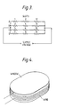
- Figure 1 shows the top portion of a window and illustrates the arrangement of one group of conducting wires;
- Figure 2 is an enlarged section view through the window of Figure 1 along the line II;
- Figure 3 Is a schematic diagram of the heating elements in Figure 1 showing the arrangement of the groups; and
- Figure 4 is a perspective view of a window wound circumferentially with a heating element, said heating element being held in position with adhesive.
- Referring to figures 1 to 3 there is illustrated an embodiment of heated window in which the heating element is placed in parallel grooves in the external surface of the window. In the embodiment illustrated, the
window 15 has a series ofparallel slots 16 scored into one surface at a regular pitch to achieve a uniform temperature gradient across the surface of the window; however they may be irregularly spaced to create a different temperature gradient across the window. A further advantage of having irregularly spaced heating elements is that they disrupt the optical interference effects which might otherwise occur. The width of each slot must be minimal to reduce obscuration of the optical system and to improve thermal conduction from the wires. Awire 17 is placed inslot 16 and a lowviscosity epoxy resin 18 or other suitable bonding agent is placed in the slot to bond the wire in place. Theresin 18 substantially just fills theslot 16 up to the level of the surface of thewindow 15 so maintaining that surface substantially uniform. - The
wires 17 are arranged in several groups over the area of the window. Figure 2 shows a group of fourwires 17 in parallel on theupper part 15 of a window. In the group shown a wire A is inlaid inslots slots slots slots slot 12 toslot 1. To overcome the difference in slot length each wire is inlaid into a combination of slot lengths so that it traverses approximately the same length of window as the other wires and so that the total length of each combination of slots is approximately the same. - Figure 3 is a schematic circuit diagram of the wiring arrangement in Figure 1 and shows how the group is connected in a series parallel arrangement. The wiring arrangement disclosed in Figures 1 and 3 is an optimum arrangement which enables a uniform heat distribution to be achieved across a window at the same time if a wire in a group should fail the failure will be localised to the single wire in that group and the rest of the group will continue to function properly.
- As shown in Figure 4, to provide additional heating of the window, one or more coils of electrical heating wire may be wound around the periphery of the window and adhered to that periphery by epoxy resin.
- The slots scored into the window surface need not be straight parallel lines but could instead have a different shape appropriate to achieve particular heat distribution effects. For instance the slots might be scored as a circle around the periphery of the window or as a circle or a series of concentric circles and the wires arranged in coiled formation within the circle or circles. In these cases the power density for a given window can be varied by using wire of a different resistivity and/or by varying the number of turns in each coil. Any cross-section of wire heating element can be used.
Claims (2)
- An electrically heatable window, for use in optical equipment for example, having an elongate electrical heating element fixed into at least one groove in the window surface, characterised in that the heating element (17) lies in the groove (16) below said surface of the window and is fixed therein by adhesive material (18), which adhesive material substantially just fills the groove up to said surface to render this surface substantially uniform.
- A window according to claim 1, including a further elongate electrical heating element wound around the periphery of the window member and bonded in place by means of adhesive.
Applications Claiming Priority (2)
| Application Number | Priority Date | Filing Date | Title |
|---|---|---|---|
| GB8619443 | 1986-08-08 | ||
| GB8619443A GB2193869B (en) | 1986-08-08 | 1986-08-08 | Heated windows |
Publications (3)
| Publication Number | Publication Date |
|---|---|
| EP0257900A2 EP0257900A2 (en) | 1988-03-02 |
| EP0257900A3 EP0257900A3 (en) | 1988-10-26 |
| EP0257900B1 true EP0257900B1 (en) | 1991-12-04 |
Family
ID=10602481
Family Applications (1)
| Application Number | Title | Priority Date | Filing Date |
|---|---|---|---|
| EP19870307057 Expired EP0257900B1 (en) | 1986-08-08 | 1987-08-10 | Heated windows |
Country Status (4)
| Country | Link |
|---|---|
| US (1) | US4845344A (en) |
| EP (1) | EP0257900B1 (en) |
| DE (1) | DE3774968D1 (en) |
| GB (1) | GB2193869B (en) |
Families Citing this family (12)
| Publication number | Priority date | Publication date | Assignee | Title |
|---|---|---|---|---|
| US5119215A (en) * | 1990-02-20 | 1992-06-02 | Thermo-O-Disc, Incorporated | LCD with self regulating PTC thermistor heating element |
| JPH0529067A (en) * | 1991-07-25 | 1993-02-05 | Rohm Co Ltd | Structure of heating element and heater for office automation equipment |
| US6137086A (en) * | 1999-02-26 | 2000-10-24 | Libbey-Owens-Ford Co. | Vehicle window with heated wiper rest |
| DE19942038C1 (en) * | 1999-09-03 | 2000-10-05 | Webasto Dachsysteme Gmbh | Sliding automobile sunroof has a sliding panel with a plastics frame and an electrical heating wire system integrated into the frame to prevent icing in cold weather |
| DE102005034155B3 (en) * | 2005-07-21 | 2006-11-16 | Eos Gmbh Electro Optical Systems | Lens for focusing electromagnetic radiation in forming layers in three-dimensional rapid prototyping includes a heating element in the exit window |
| CA2628517C (en) * | 2007-10-17 | 2013-08-13 | Adm21 Co., Ltd. | Wiper blade with heating elements |
| DE102007062047A1 (en) | 2007-12-21 | 2009-07-16 | Osram Opto Semiconductors Gmbh | compact housing |
| US8124868B2 (en) | 2008-12-16 | 2012-02-28 | Solutia Inc. | Thin film photovoltaic module with contoured deairing substrate |
| GB0918228D0 (en) | 2009-10-19 | 2009-12-02 | Pilkington Group Ltd | Heatable glazing |
| FR2991243B1 (en) * | 2012-05-30 | 2015-01-02 | Peugeot Citroen Automobiles Sa | FRICTIONAL GLAZING COMPRISING A GROOVED PANEL, VEHICLE EQUIPPED WITH SAID GLAZING AND METHOD OF MANUFACTURING THE GLAZING. |
| DE102014107480B4 (en) * | 2014-05-27 | 2016-02-04 | Webasto SE | Plastic rear window with rear window heating and method of making the same |
| US10079640B1 (en) * | 2014-07-31 | 2018-09-18 | Collinear Networks, Inc. | Window heater with reduced wavefront distortion |
Family Cites Families (10)
| Publication number | Priority date | Publication date | Assignee | Title |
|---|---|---|---|---|
| NL96071C (en) * | ||||
| US1565046A (en) * | 1925-04-06 | 1925-12-08 | Homer S Bergdoll | Windshield heater |
| US1822884A (en) * | 1929-02-19 | 1931-09-15 | George J Creighton | Heater for automotive shields |
| DE928310C (en) * | 1940-08-23 | 1955-05-31 | Ver Glaswerke Gmbh | Electrically heatable glass pane |
| DE1968844U (en) * | 1967-05-23 | 1967-09-21 | Eltro G M B H & Co Ges Fuer St | ELECTRIC HEATING FOR EXIT WINDOWS OR FRONT LENSES OF OPTICAL DEVICES. |
| US3484583A (en) * | 1968-07-23 | 1969-12-16 | Ppg Industries Inc | Combination of electrically heated transparent window and antenna |
| GB2028070A (en) * | 1978-08-08 | 1980-02-27 | Crystal Glass Ind Ltd | An improved method of affixing an electrical heater element to a glass pane |
| US4250396A (en) * | 1979-09-04 | 1981-02-10 | Walter Leuca | Heated drafting board |
| DE2950321A1 (en) * | 1979-12-14 | 1981-06-19 | Kabel- und Metallwerke Gutehoffnungshütte AG, 3000 Hannover | Flat heating element for wing mirror of vehicle - has serpentine resistance wire applied to adhesive on backing and with covering |
| US4552611A (en) * | 1983-08-26 | 1985-11-12 | Astrolab Inc. | Conductor applying apparatus for rear window defrosters |
-
1986
- 1986-08-08 GB GB8619443A patent/GB2193869B/en not_active Expired - Lifetime
-
1987
- 1987-08-06 US US07/082,131 patent/US4845344A/en not_active Expired - Fee Related
- 1987-08-10 DE DE8787307057T patent/DE3774968D1/en not_active Expired - Fee Related
- 1987-08-10 EP EP19870307057 patent/EP0257900B1/en not_active Expired
Also Published As
| Publication number | Publication date |
|---|---|
| GB2193869A (en) | 1988-02-17 |
| EP0257900A2 (en) | 1988-03-02 |
| US4845344A (en) | 1989-07-04 |
| GB2193869B (en) | 1990-03-21 |
| DE3774968D1 (en) | 1992-01-16 |
| EP0257900A3 (en) | 1988-10-26 |
| GB8619443D0 (en) | 1986-12-17 |
Similar Documents
| Publication | Publication Date | Title |
|---|---|---|
| EP0257900B1 (en) | Heated windows | |
| US4737618A (en) | Heating element for a defrosting device for a wing structure, such a device and a process for obtaining same | |
| US4388522A (en) | Electrically heated backlite structure | |
| US4396826A (en) | Lightweight heated plastic window element with unique bus bar system | |
| US2878357A (en) | Electric heated laminated glass panel | |
| US20190141792A1 (en) | Pane having an electric heating layer | |
| JP6978940B2 (en) | Heatable glass panel | |
| US10638550B2 (en) | Pane with an electrical heating region | |
| US4278875A (en) | Electrically heated window | |
| KR101782333B1 (en) | Electrically heated window | |
| KR101345050B1 (en) | Transparent article which can be electrically extensively heated, method for the production thereof and the use thereof | |
| EP1183912B1 (en) | Automotive glazing panel having an electrically heatable solar control coating layer | |
| US3484583A (en) | Combination of electrically heated transparent window and antenna | |
| US2932710A (en) | Construction in electrically conducting transparent panel | |
| BRPI0707182A2 (en) | transparent pane with a stratified heater system | |
| US20070108175A1 (en) | Heated laminated glazing | |
| KR20090099503A (en) | Heating element and method for manufacturing the same | |
| JPH10189232A (en) | Laminated transparent body | |
| US2526327A (en) | Windshield deicer | |
| US7186952B2 (en) | Heatable glazing panel with electrically conductive coating having both heatable and non-heatable coated zones | |
| US10660161B2 (en) | Transparent pane having an electrical heating layer, method for its production, and its use | |
| US20210070019A1 (en) | Automotive laminate with invisible heating and high red ratio for camera defroster | |
| EP2063685A1 (en) | Plastic glazing | |
| US20230352208A1 (en) | Connection arrangement with a flexible flat cable | |
| US5132162A (en) | Heated glazing |
Legal Events
| Date | Code | Title | Description |
|---|---|---|---|
| PUAI | Public reference made under article 153(3) epc to a published international application that has entered the european phase |
Free format text: ORIGINAL CODE: 0009012 |
|
| AK | Designated contracting states |
Kind code of ref document: A2 Designated state(s): DE FR GB |
|
| PUAL | Search report despatched |
Free format text: ORIGINAL CODE: 0009013 |
|
| AK | Designated contracting states |
Kind code of ref document: A3 Designated state(s): DE FR GB |
|
| 17P | Request for examination filed |
Effective date: 19881116 |
|
| 17Q | First examination report despatched |
Effective date: 19891130 |
|
| GRAA | (expected) grant |
Free format text: ORIGINAL CODE: 0009210 |
|
| AK | Designated contracting states |
Kind code of ref document: B1 Designated state(s): DE FR GB |
|
| ET | Fr: translation filed | ||
| REF | Corresponds to: |
Ref document number: 3774968 Country of ref document: DE Date of ref document: 19920116 |
|
| PG25 | Lapsed in a contracting state [announced via postgrant information from national office to epo] |
Ref country code: GB Effective date: 19920810 |
|
| PGFP | Annual fee paid to national office [announced via postgrant information from national office to epo] |
Ref country code: FR Payment date: 19920831 Year of fee payment: 6 |
|
| RAP4 | Party data changed (patent owner data changed or rights of a patent transferred) |
Owner name: BRITISH AEROSPACE PUBLIC LIMITED COMPANY |
|
| PLBE | No opposition filed within time limit |
Free format text: ORIGINAL CODE: 0009261 |
|
| STAA | Information on the status of an ep patent application or granted ep patent |
Free format text: STATUS: NO OPPOSITION FILED WITHIN TIME LIMIT |
|
| PGFP | Annual fee paid to national office [announced via postgrant information from national office to epo] |
Ref country code: DE Payment date: 19921102 Year of fee payment: 6 |
|
| 26N | No opposition filed | ||
| GBPC | Gb: european patent ceased through non-payment of renewal fee |
Effective date: 19920810 |
|
| PG25 | Lapsed in a contracting state [announced via postgrant information from national office to epo] |
Ref country code: FR Effective date: 19940429 |
|
| PG25 | Lapsed in a contracting state [announced via postgrant information from national office to epo] |
Ref country code: DE Effective date: 19940503 |
|
| REG | Reference to a national code |
Ref country code: FR Ref legal event code: ST |