EP0257840B1 - Burner - Google Patents
Burner Download PDFInfo
- Publication number
- EP0257840B1 EP0257840B1 EP87306841A EP87306841A EP0257840B1 EP 0257840 B1 EP0257840 B1 EP 0257840B1 EP 87306841 A EP87306841 A EP 87306841A EP 87306841 A EP87306841 A EP 87306841A EP 0257840 B1 EP0257840 B1 EP 0257840B1
- Authority
- EP
- European Patent Office
- Prior art keywords
- chamber
- burner
- heat storage
- mixing position
- burner according
- Prior art date
- Legal status (The legal status is an assumption and is not a legal conclusion. Google has not performed a legal analysis and makes no representation as to the accuracy of the status listed.)
- Expired - Lifetime
Links
- 238000005338 heat storage Methods 0.000 claims abstract description 67
- 239000000446 fuel Substances 0.000 claims abstract description 48
- 230000002093 peripheral effect Effects 0.000 claims description 4
- 239000003381 stabilizer Substances 0.000 claims description 3
- 238000011144 upstream manufacturing Methods 0.000 claims description 3
- 238000010304 firing Methods 0.000 claims 1
- 239000000203 mixture Substances 0.000 claims 1
- 238000002485 combustion reaction Methods 0.000 abstract description 30
- 238000000034 method Methods 0.000 abstract 1
- 239000007789 gas Substances 0.000 description 10
- 238000001514 detection method Methods 0.000 description 4
- 239000000463 material Substances 0.000 description 4
- 229910010293 ceramic material Inorganic materials 0.000 description 2
- 239000002657 fibrous material Substances 0.000 description 2
- 238000010438 heat treatment Methods 0.000 description 2
- 238000009434 installation Methods 0.000 description 2
- VNWKTOKETHGBQD-UHFFFAOYSA-N methane Chemical compound C VNWKTOKETHGBQD-UHFFFAOYSA-N 0.000 description 2
- 125000006850 spacer group Chemical group 0.000 description 2
- 238000009825 accumulation Methods 0.000 description 1
- 238000013459 approach Methods 0.000 description 1
- 238000004140 cleaning Methods 0.000 description 1
- 239000011521 glass Substances 0.000 description 1
- 239000002184 metal Substances 0.000 description 1
- 239000003345 natural gas Substances 0.000 description 1
- 239000002245 particle Substances 0.000 description 1
- 239000007787 solid Substances 0.000 description 1
Images

Classifications
-
- F—MECHANICAL ENGINEERING; LIGHTING; HEATING; WEAPONS; BLASTING
- F27—FURNACES; KILNS; OVENS; RETORTS
- F27D—DETAILS OR ACCESSORIES OF FURNACES, KILNS, OVENS OR RETORTS, IN SO FAR AS THEY ARE OF KINDS OCCURRING IN MORE THAN ONE KIND OF FURNACE
- F27D99/00—Subject matter not provided for in other groups of this subclass
- F27D99/0001—Heating elements or systems
- F27D99/0033—Heating elements or systems using burners
-
- F—MECHANICAL ENGINEERING; LIGHTING; HEATING; WEAPONS; BLASTING
- F23—COMBUSTION APPARATUS; COMBUSTION PROCESSES
- F23L—SUPPLYING AIR OR NON-COMBUSTIBLE LIQUIDS OR GASES TO COMBUSTION APPARATUS IN GENERAL ; VALVES OR DAMPERS SPECIALLY ADAPTED FOR CONTROLLING AIR SUPPLY OR DRAUGHT IN COMBUSTION APPARATUS; INDUCING DRAUGHT IN COMBUSTION APPARATUS; TOPS FOR CHIMNEYS OR VENTILATING SHAFTS; TERMINALS FOR FLUES
- F23L15/00—Heating of air supplied for combustion
- F23L15/02—Arrangements of regenerators
-
- Y—GENERAL TAGGING OF NEW TECHNOLOGICAL DEVELOPMENTS; GENERAL TAGGING OF CROSS-SECTIONAL TECHNOLOGIES SPANNING OVER SEVERAL SECTIONS OF THE IPC; TECHNICAL SUBJECTS COVERED BY FORMER USPC CROSS-REFERENCE ART COLLECTIONS [XRACs] AND DIGESTS
- Y02—TECHNOLOGIES OR APPLICATIONS FOR MITIGATION OR ADAPTATION AGAINST CLIMATE CHANGE
- Y02E—REDUCTION OF GREENHOUSE GAS [GHG] EMISSIONS, RELATED TO ENERGY GENERATION, TRANSMISSION OR DISTRIBUTION
- Y02E20/00—Combustion technologies with mitigation potential
- Y02E20/34—Indirect CO2mitigation, i.e. by acting on non CO2directly related matters of the process, e.g. pre-heating or heat recovery
Definitions
- the present invention relates to a burner in or for use in a furnace, the burner defining separate paths for leading fuel and air to a mixing position and defining a path along which there can be viewed a flame extending from the mixing position into a heating chamber of the furnace, when the burner is in use, wherein the burner incorporates heat storage means contained in a chamber which forms a part of the air path, wherein the burner comprises a housing which is specific to the burner and wherein the housing is mounted on or is suitable for mouting on a wall of the furnace.
- Such additional services include an ignition device, flame-detection means and a pilot burner fuel supply.
- the heat storage means associated with the burner disclosed in EP 111382 is spaced a considerable distance from the mixing position.
- a body of the burner In the region between the mixing position and the heat storage means, there is defined by a body of the burner a bore which is inclined at an angle in the region of 45° to a longitudinal axis of the burner.
- a tube extends from the housing of the burner in alignment with the bore and the tube is provided with a sight glass.
- a partial view of the mixing position can be obtained through the tube and the bore. It is necessary for the bore to be inclined to the longitudinal axis of the burner at an angle which is not significantly greater than 45°, in order that a part of the flame can be viewed, when the burner is in operation. This necessitates spacing of the heat storage means a substantial distance from the mixing position, in order to accommodate the inclined bore between them.
- a burner comprising a housing, inside which there are defined respective paths for the flow of fuel and air to a mixing position, wherein the air flow path includes a chamber within the housing, characterised in that the chamber and the mixing position are separated by a permeable wall defining an end of the chamber and in that the chamber is upstream of the mixing position and contains a permeable heat storage mass to form a bed in the chamber.
- the heat storage mass may occupy the chamber in such a way that the heat storage mass is substantially immediately adjacent to the mixing position.
- This arrangement provides a burner which is more compact than is a structure as disclosed in EP 111382A, intended for the same duty. It will be understood that, if the burner has a large bulk protruding from the furnace wall, this can be inconvenient, and in some situations, installation of the burner may be impossible. Furthermore, the smaller structure constituted by a burner having this preferred feature will generally be less massive than is the known structure. The mass of the burner affects considerably the ease of installation and removal of the burner.
- said wall may be constructed as a flame stabiliser and the mixing position may be spaced from the heat storage means only by the flame stabiliser.
- the burner preferably defines a space which extends through the heat storage means from the mixing position to a position outside the housing of the burner.
- the fuel flow path may include a fuel supply pipe which extends along this space.
- the fuel supply pipe preferably occupies a part only of the transverse cross-section of the space.
- the remainder of the space is available to contain other services, for example flame-detection means, a fuel supply for a pilot flame and an ignition device.
- the remainder of the space can provide a substantially axial view of the flame and can direct to the mixing position a supply of air which does not pass through the heat storage means.
- An axial view of a flame provides information which is different from that provided by a transverse view, as provided in the structure disclosed in EP 111382A.
- the heat storage mass in the chamber preferably comprises a bed composed of a loose collection of separately formed bodies.
- the size of the bodies preferably varies in a direction along the airflow path.
- the heat storage bodies immediately adjacent to the mixing position may be larger than the heat storage bodies which occupy a part of the chamber remote from the mixing position.
- a bed is meant herein a collection of distinct elements, each of which is small, as compared with the size of the bed.
- the chamber is preferably elongated, being arranged with its length extending along the length of the fuel flow path and along the flame axis of the burner.
- the wall which separates the chamber from the mixing position can be robust. In a case where the wall will be subjected to temperatures not significantly above 1000°C, the wall may be metallic. In cases where the wall is to be subjected to much higher temperatures, the wall can be formed of ceramic materials and can have whatever thickness is necessary to provide the desired strength. Even when the wall is thick, the wall can be constructed to impose only a very low pressure drop on gases flowing through the openings defined by the wall. Gases flowing through the chamber are preferably directed along the chamber. This provides a relatively long flowpath within the chamber and enables a relatively long cycle time to be used.
- the burner is preferably mounted in the wall of a furnace to communicate with the interior of the furnace through an opening defined in the wall of the furnace, the chamber being disposed at the outside of the furnace wall.
- the mixing position also may be outside the furnace wall.
- the furnace includes walls defining a chamber 10 within which workpieces or materials are to be heated.
- the furnace includes an entrance and means may be provided for introducing workpieces or materials into the chamber 10 and transferring workpieces or materials out of the chamber 10.
- One of the walls, 11, defines two openings and there are mounted on the wall 11, partly lying outside the furnace, respective burners 12 and 13 which communicate with the chamber 10 through these openings.
- the burners are operated alternately in a cyclical manner. During a first half of each cycle, fuel and air are supplied separately to the burner 12, are mixed by the burner and burn as they are discharged from the burner through the opening in the wall 11 into the chamber 10.
- Hot products of combustion pass from the chamber 10 through the burner 13 and associated heat storage means 30 to a flue 14. Heat is extracted from the products of combustion and stored in the burner 13 and the heat storage means 30 so that the products of combustion discharged to the flue are cool, relative to the products of combustion in the chamber 10 during steady-state operation.
- the temperature of the gases in the chamber 10 may be within the range 800° to 1400°C; whereas the temperature of the gases leaving the burner 13 may be in the range 500° to 700°C and the temperature of the gases leaving the heat storage means 30 may be in the range 100° to 200°C.
- air and fuel are supplied separately to the burner 13.
- the air is heated in the heat storage means and in the burner from ambient temperature to a temperature which is typically within the range 700° to 1200°C, before being mixed in the burner 13 with the fuel.
- the fuel and hot air burn as they pass from the burner into the chamber 10 and the hot products of combustion are withdrawn from the chamber through the burner 12.
- the burner 12 and heat storage means 31 associated therewith extract heat from the products of combustion, before these are discharged to the flue 14.
- fuel supply means 15 For supplying fuel to the burners alternately, there is provided fuel supply means indicated by the reference number 15.
- the fuel is typically natural gas and the supply means 15 may include a gas main and valves for controlling the flow of gas from the main to each of the burners.
- the air supply means includes a fan and one or more valves associated with the burners 12 and 13 for directing air from the fan to one of the burners and directing products of combustion from the other of the burners to the flue 14.
- a further fan (not shown) may be provided upstream of the flue 14.
- the structure of the burner 12 is illustrated in more detail in figure 2.
- the burner includes a housing 18 which is disposed partly within and partly outside the furnace wall 11 and which is attached to that wall.
- the axis of the chamber 19 is represented at 21 in figure 2 and is typically perpendicular to the external surface of the wall 11.
- the chamber is separated from the mixing position 23 by an array 32 of rods which collectively form a permeable wall defining one end of the chamber.
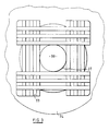
- the array comprises two layers of rods, the rods of a first of the layers being parallel to one another and the rods of the second layer being parallel to one another and perpendicular to the rods of the first layer. All of the rods are perpendicular to the axis 21 as shown in Figure 3, there are defined between the rods gaps 33 through which gases can flow without significant resistance. Opposite end portions of each rod are seated in an annular recess defined by an annular block 34 at the periphery of the chamber 19.
- the rods of the array 32 are preferably formed of a ceramic material. It will be understood that other forms of permeable wall structure may be substituted for the array 32. In place of solid rods, there may be provided tubular members. The wall is transverse to the axis 21 in each case.
- the chamber 19 contains a permeable heat storage mass which may be a single body of permeable material but which preferably comprises a number of heat storage bodies 26 which are initially separate from one another but are packed into the chamber 19 to form a bed occupying that chamber substantially entirely, except for interstices between the bodies. Heat storage bodies of the bed rest against the array 32 and against a wall of the housing 18 which defines an opposite end of the bed.
- the heat storage bodies 26 provided in the chamber 19 adjacent to the array 32 are larger than the heat storage bodies disposed further along the chamber.
- the heat storage mass may comprise heat storage bodies of two or more different sizes, those of the larger size being generally near to the array 32 and those of the smaller size being spaced from the array.
- Each of the heat storage bodies 26 is small, as compared with the bed of bodies in the chamber 19. However, the bodies are not so small as to properly be designated particles or grit. Each of the bodies preferably has at least one dimension which exceeds five millimetre.
- each of the heat storage bodies 26, particularly adjacent to the array 32 is substantially larger than grit, the interstices defined by the array 32 can be quite large. Accordingly, the array does not cause a significant pressure drop in gases flowing through the array. Furthermore, the array is robust and is not prone to blockage by accumulation of foreign matter within the interstices defined by the array. These interstices are preferably at least five millimetre across. Mutually adjacent interstices defined by the array are separated by structural parts of the array and these parts have a width, measured in a direction between the two adjacent interstices, similar to the width of the interstices measured in the same direction.
- the thickness of the array 32 between a face of the array presented to the bed of heat storage bodies 26 and an opposite face of the array is in excess of ten millimetre, exceeds the largest dimension of the bodies 26, exceeds the largest dimension of each interstice defined by the array and exceeds the internal diameter of the fuel pipe 22 adjacent to the free-end thereof.
- the diameter of the chamber 19 where the radially inwardly facing surface of the annular block 34 meets the array 32 is no more than twenty five times the thickness of the array and may be no more than twice the thickness of the array.
- the radially inwardly facing surface of the annular block 34 is of conical form, the smaller diameter being immediately adjacent to the array 32 and the larger diameter being spaced away from the array in a direction towards a rear end of the chamber 19 remote from the mixing position 23.
- the annulus 34 serves partly to support the weight of the heat storage bodies 26 and partly to prevent movement of the heat storage bodies from the chamber 19 in a direction towards the mixing position 23.
- the peripheral boundary of the chamber 19 is defined by a refractory lining 27 inside the housing 18.
- a layer of this lining which is nearer to the axis 21 is preferably formed of a fibrous material.
- a hollow, impermeable support 37 which defines the radially innermost boundary of the chamber 19 and is therefore surrounded by the bed of refractory bodies.
- the support 37 may be cylindrical and is preferably co-axial with the fuel pipe 22.
- the internal diameter of the support 37 is substantially greater, preferably a plurality of times greater, than the external diameter of the fuel pipe 22 so that there is between the fuel pipe and the support an annular space 38.
- a flow of air may be directed along the annular space 38 towards the mixing position 23 to extract heat from the fuel pipe 22 and/or to reduce the flow of heat to that fuel pipe through the support 37.
- the support 37 is impermeable to gases. Bodies 26 rest on the support.
- the support 37 approaches sufficiently closely to the array 32 to prevent refractory bodies 26 escaping from the chamber 19 in a direction towards the mixing position 23. It will be noted that there is at the centre of the array 32 an unobstructed space 39 having a width approximately equal to the outside diameter of the support 37.
- the fuel pipe 22, or a nozzle provided thereon may extend through the space 39 to the mixing position, into, but not completely through this space, or may terminate at the side of the array 32 remote from the mixing position. It will be noted that the array 32 is separate from the support 37 and from the fuel pipe 22.
- the support 37 is preferably spaced from the array 32 in a direction along the axis 21. However, it would be within the scope of the invention for an end portion of the support 37 to extend into the space 39.
- a pilot burner and associated fuel-supply line 40 extends along the annular space 38 and terminates at a position outside the fuel pipe 22 but just inside the tube 37. Adjacent to the pilot burner, there is provided a flame-detection device 41 and connection means connecting the flame-detection device with control means of the burners also extends along the annular space 38. Additional sensing and control devices can be accommodated in the space 38, at the inside of the hollow support 37.
- the heat storage means 31 may be constructed and arranged in a known manner and comprises a further mass of refractory bodies in a thermally insulated container.
- the container is spaced somewhat from the burner 12 and is connected with the inlet 36 of the burner by a thermally insulated duct 42.
- the structure of the burner 13 may be identical with that of the burner illustrated in figures 2 and 3.
- the heat storage means 30 is connected with the burner 13 by a thermally insulated duct 43 and the heat storage means 30 may be identical with the heat storage means 31.
- the fuel flowpath through that burner is closed by the fuel supply means 15 and the products of combustion which enter the burner from the opening 20 pass through the array 32 into the chamber 19.
- heat is transferred from the products of combustion to the heat storage mass so that the products of combustion are considerably cooler, when they flow from the chamber 19 into the duct 42, than when they flow into the chamber 19.
- the peripheral boundary of the chamber 19 is preferably tapered towards the inlet 36, to reduce the cross-sectional area of the airflow path in a direction from the array 32 towards the inlet, so that the velocity of the products of combustion does not fall unduly as the temperature falls.
- the arrangement is such that the velocity of the products of combustion in the chamber 19 is maintained at a sufficiently high value to achieve good heat transfer to the heat storage mass.
- the products of combustion flow through the inlet 36 in a direction away from the axis 21. It will be noted that the inlet extends towards the axis to a position nearer to that axis than the peripheral boundary of the chamber 19 but does not extend to the axis. Surprisingly, the flow of products of combustion is distributed substantially evenly throughout the bed of refractory bodies 26. Similarly, when combustion air enters the burner through the inlet 36, the flow of combustion air through the bed of refractory bodies 26 is distributed more or less evenly throughout the bed.
- the flow of air through the chamber 19 and the flow of products of combustion through that chamber are generally in axial directions. The air flow leaves that chamber and the products of combustion enter that chamber also in generally axial directions.
- the fuel pipe 22 is shielded by the hollow support 37 from direct contact with the hot products of combustion flowing through the chamber 19 when products of combustion are discharged from the chamber 10 through the burner 12.
- the products of combustion flow from the burner 12 through the duct 42 to the heat storage means 31, where the products of combustion are further cooled and the heat extracted from the products of combustion is stored in the heat storage bodies.
- the proportion which is stored in the burner is preferably at least one tenth and more preferably exceeds one fifth and is typically one half.
- Flow of air through the array 32 promotes turbulence of that flow at the mixing position.
- the array stabilizes a flame at the mixing position.
- the burner may be constructed to permit removal of the heat storage bodies from the burner whilst the burner remains mounted on the furnace wall 11.
- the burner may be demounted and the bodies removed from the chamber 10 at the end thereof which is adjacent to the mixing position. It will be noted that foreign matter will accummulate on the heat storage bodies in the burner, rather than on heat storage bodies in the heat storage means 31 and that cleaning or replacement of all of the heat storage bodies provided will not generally be necessary.
- the apparatus illustrated in the accompanying drawing may be modified so that the air inlet 36 extends through the circumferential wall of the chamber 19 and through the lining but merges smoothly with the surface of the lining which is nearest to the axis 21 so that the air inlet does not lie significantly nearer to that axis than is the lining.
- the end portion of the air inlet nearer to the axis may be outwardly flared, to promote distribution of the flow throughout the chamber.
- the air inlet as viewed in a direction towards the axis 21, may be circular, square or otherwise rectangular.
- a layer of expanded metal may be present around the circumference of the bed of heat storage bodies 26. Such a layer distributes over the lining pressure exerted by the bodies 26 and prevents those bodies leaving the chamber through the air inlet, during transport of the burner to the place of use.
- the period occupied by a complete cycle of operation is preferably at least thirty seconds. More preferably, the period during which fuel is supplied continuously to one of the burners when that burner is operating in the fire mode is at least thirty seconds so that a complete cycle will occupy a period in excess of one minute.
- the apparatus illustrated in the accompanying drawing may be modified by omission of the heat storage means 30, the duct 43, the heat storage means 31 and the duct 42.
- the heat storage means is contained entirely within the burners and only parts of the furnace and parts of the burners are exposed to high temperatures.
- there are no ducts, valves or joints outside the burners which are subjected to temperatures similar to those attained in the furnace chamber 10.
Landscapes
- Engineering & Computer Science (AREA)
- Mechanical Engineering (AREA)
- General Engineering & Computer Science (AREA)
- Chemical & Material Sciences (AREA)
- Combustion & Propulsion (AREA)
- Air Supply (AREA)
- Manufacture, Treatment Of Glass Fibers (AREA)
- Organic Insulating Materials (AREA)
- Addition Polymer Or Copolymer, Post-Treatments, Or Chemical Modifications (AREA)
- Fluidized-Bed Combustion And Resonant Combustion (AREA)
- Drying Of Solid Materials (AREA)
- Surgical Instruments (AREA)
- Saccharide Compounds (AREA)
- Percussion Or Vibration Massage (AREA)
Abstract
Description
- The present invention relates to a burner in or for use in a furnace, the burner defining separate paths for leading fuel and air to a mixing position and defining a path along which there can be viewed a flame extending from the mixing position into a heating chamber of the furnace, when the burner is in use, wherein the burner incorporates heat storage means contained in a chamber which forms a part of the air path, wherein the burner comprises a housing which is specific to the burner and wherein the housing is mounted on or is suitable for mouting on a wall of the furnace.
- In a burner intended for supplying heat to a heating chamber of a furnace, it is generally necessary to provide access through the burner to the mixing position for services additional to the fuel and air supply. Such additional services include an ignition device, flame-detection means and a pilot burner fuel supply.
- An example of a burner which defines separate paths for leading fuel and air to a mixing position and which defines a path along which there can be viewed a flame extending from the mixing position is disclosed in EP 111382A. This published specification discloses mounting of the burner on a wall of the furnace with the mixing position lying within an opening in that wall. The published specification further discloses a housing containing a heat storage means, the housing of the heat storage means being bolted to a housing of the burner so that the heat storage means extends from the burner in a direction away from the furnace wall.
- The heat storage means associated with the burner disclosed in EP 111382 is spaced a considerable distance from the mixing position. In the region between the mixing position and the heat storage means, there is defined by a body of the burner a bore which is inclined at an angle in the region of 45° to a longitudinal axis of the burner. A tube extends from the housing of the burner in alignment with the bore and the tube is provided with a sight glass. A partial view of the mixing position can be obtained through the tube and the bore. It is necessary for the bore to be inclined to the longitudinal axis of the burner at an angle which is not significantly greater than 45°, in order that a part of the flame can be viewed, when the burner is in operation. This necessitates spacing of the heat storage means a substantial distance from the mixing position, in order to accommodate the inclined bore between them.
- According to the present invention, there is provided a burner comprising a housing, inside which there are defined respective paths for the flow of fuel and air to a mixing position, wherein the air flow path includes a chamber within the housing, characterised in that the chamber and the mixing position are separated by a permeable wall defining an end of the chamber and in that the chamber is upstream of the mixing position and contains a permeable heat storage mass to form a bed in the chamber.
- The heat storage mass may occupy the chamber in such a way that the heat storage mass is substantially immediately adjacent to the mixing position. This arrangement provides a burner which is more compact than is a structure as disclosed in EP 111382A, intended for the same duty. It will be understood that, if the burner has a large bulk protruding from the furnace wall, this can be inconvenient, and in some situations, installation of the burner may be impossible. Furthermore, the smaller structure constituted by a burner having this preferred feature will generally be less massive than is the known structure. The mass of the burner affects considerably the ease of installation and removal of the burner.
- In a burner in accordance with the present invention, said wall may be constructed as a flame stabiliser and the mixing position may be spaced from the heat storage means only by the flame stabiliser.
- The burner preferably defines a space which extends through the heat storage means from the mixing position to a position outside the housing of the burner. The fuel flow path may include a fuel supply pipe which extends along this space. In this case, the fuel supply pipe preferably occupies a part only of the transverse cross-section of the space. With this arrangement, the remainder of the space is available to contain other services, for example flame-detection means, a fuel supply for a pilot flame and an ignition device. Furthermore, the remainder of the space can provide a substantially axial view of the flame and can direct to the mixing position a supply of air which does not pass through the heat storage means. An axial view of a flame provides information which is different from that provided by a transverse view, as provided in the structure disclosed in EP 111382A.
- The heat storage mass in the chamber preferably comprises a bed composed of a loose collection of separately formed bodies. In this case, the size of the bodies preferably varies in a direction along the airflow path. For example, the heat storage bodies immediately adjacent to the mixing position may be larger than the heat storage bodies which occupy a part of the chamber remote from the mixing position. By a bed, is meant herein a collection of distinct elements, each of which is small, as compared with the size of the bed.
- The chamber is preferably elongated, being arranged with its length extending along the length of the fuel flow path and along the flame axis of the burner. The wall which separates the chamber from the mixing position can be robust. In a case where the wall will be subjected to temperatures not significantly above 1000°C, the wall may be metallic. In cases where the wall is to be subjected to much higher temperatures, the wall can be formed of ceramic materials and can have whatever thickness is necessary to provide the desired strength. Even when the wall is thick, the wall can be constructed to impose only a very low pressure drop on gases flowing through the openings defined by the wall. Gases flowing through the chamber are preferably directed along the chamber. This provides a relatively long flowpath within the chamber and enables a relatively long cycle time to be used.
- For use, the burner is preferably mounted in the wall of a furnace to communicate with the interior of the furnace through an opening defined in the wall of the furnace, the chamber being disposed at the outside of the furnace wall. The mixing position also may be outside the furnace wall.
- An example of a furnace which includes two burners embodying the invention will now be described, with reference to the accompanying drawings, wherein:-
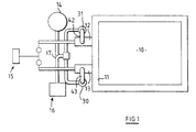
- FIGURE 1 shows a diagrammatic representation of the furnace, burners and associated equipment;
- FIGURE 2 shows diagrammatically a cross-section through one of the burners and an adjacent part of the furnace; and
- FIGURE 3 shows certain details of the burner of Figure 2.
- The furnace includes walls defining a
chamber 10 within which workpieces or materials are to be heated. The furnace includes an entrance and means may be provided for introducing workpieces or materials into thechamber 10 and transferring workpieces or materials out of thechamber 10. However, as these details form no part of the present invention, they are not represented in the drawing. One of the walls, 11, defines two openings and there are mounted on thewall 11, partly lying outside the furnace,respective burners 12 and 13 which communicate with thechamber 10 through these openings. The burners are operated alternately in a cyclical manner. During a first half of each cycle, fuel and air are supplied separately to the burner 12, are mixed by the burner and burn as they are discharged from the burner through the opening in thewall 11 into thechamber 10. Hot products of combustion pass from thechamber 10 through theburner 13 and associated heat storage means 30 to aflue 14. Heat is extracted from the products of combustion and stored in theburner 13 and the heat storage means 30 so that the products of combustion discharged to the flue are cool, relative to the products of combustion in thechamber 10 during steady-state operation. Typically, the temperature of the gases in thechamber 10 may be within the range 800° to 1400°C; whereas the temperature of the gases leaving theburner 13 may be in the range 500° to 700°C and the temperature of the gases leaving the heat storage means 30 may be in the range 100° to 200°C. During the second half of the cycle, air and fuel are supplied separately to theburner 13. The air is heated in the heat storage means and in the burner from ambient temperature to a temperature which is typically within the range 700° to 1200°C, before being mixed in theburner 13 with the fuel. The fuel and hot air burn as they pass from the burner into thechamber 10 and the hot products of combustion are withdrawn from the chamber through the burner 12. During the second half of the cycle, the burner 12 and heat storage means 31 associated therewith extract heat from the products of combustion, before these are discharged to theflue 14. - For supplying fuel to the burners alternately, there is provided fuel supply means indicated by the
reference number 15. The fuel is typically natural gas and the supply means 15 may include a gas main and valves for controlling the flow of gas from the main to each of the burners. - For supplying air alternately to the burners, there is provided air supply means identified by the
reference numeral 16. The air supply means includes a fan and one or more valves associated with theburners 12 and 13 for directing air from the fan to one of the burners and directing products of combustion from the other of the burners to theflue 14. A further fan (not shown) may be provided upstream of theflue 14. - The structure of the burner 12 is illustrated in more detail in figure 2. The burner includes a
housing 18 which is disposed partly within and partly outside thefurnace wall 11 and which is attached to that wall. Within thehousing 18, there is defined anannular chamber 19 which is in co-axial relation with acircular opening 20 defined by thewall 11. The axis of thechamber 19 is represented at 21 in figure 2 and is typically perpendicular to the external surface of thewall 11. - At the centre of the
annular chamber 19, there isfuel pipe 22 defining a fuel-flow path from the fuel supply means 15 to amixing position 23 which lies outside thepipe 22, beyond the free-end thereof. - At the end of the
chamber 19 which is adjacent to the free-end of thepipe 22, the chamber is separated from themixing position 23 by anarray 32 of rods which collectively form a permeable wall defining one end of the chamber. The array comprises two layers of rods, the rods of a first of the layers being parallel to one another and the rods of the second layer being parallel to one another and perpendicular to the rods of the first layer. All of the rods are perpendicular to the axis 21 as shown in Figure 3, there are defined between therods gaps 33 through which gases can flow without significant resistance. Opposite end portions of each rod are seated in an annular recess defined by anannular block 34 at the periphery of thechamber 19. Spacers are interposed between the corresponding end portions of mutually adjacent rods to maintain thegaps 33 and the assembly of rods and spacers is held in the recess of theblock 34 by a gasket and afurther block 35. The rods of thearray 32 are preferably formed of a ceramic material. It will be understood that other forms of permeable wall structure may be substituted for thearray 32. In place of solid rods, there may be provided tubular members. The wall is transverse to the axis 21 in each case. - The
chamber 19 contains a permeable heat storage mass which may be a single body of permeable material but which preferably comprises a number ofheat storage bodies 26 which are initially separate from one another but are packed into thechamber 19 to form a bed occupying that chamber substantially entirely, except for interstices between the bodies. Heat storage bodies of the bed rest against thearray 32 and against a wall of thehousing 18 which defines an opposite end of the bed. - Preferably, the
heat storage bodies 26 provided in thechamber 19 adjacent to thearray 32 are larger than the heat storage bodies disposed further along the chamber. The heat storage mass may comprise heat storage bodies of two or more different sizes, those of the larger size being generally near to thearray 32 and those of the smaller size being spaced from the array. Alternatively, there may be heat storage bodies of a large number of different sizes, the average size in a region adjacent to thearray 32 being larger than the average size in a region spaced from the array. - Each of the
heat storage bodies 26 is small, as compared with the bed of bodies in thechamber 19. However, the bodies are not so small as to properly be designated particles or grit. Each of the bodies preferably has at least one dimension which exceeds five millimetre. - Since each of the
heat storage bodies 26, particularly adjacent to thearray 32, is substantially larger than grit, the interstices defined by thearray 32 can be quite large. Accordingly, the array does not cause a significant pressure drop in gases flowing through the array. Furthermore, the array is robust and is not prone to blockage by accumulation of foreign matter within the interstices defined by the array. These interstices are preferably at least five millimetre across. Mutually adjacent interstices defined by the array are separated by structural parts of the array and these parts have a width, measured in a direction between the two adjacent interstices, similar to the width of the interstices measured in the same direction. - The thickness of the
array 32 between a face of the array presented to the bed ofheat storage bodies 26 and an opposite face of the array is in excess of ten millimetre, exceeds the largest dimension of thebodies 26, exceeds the largest dimension of each interstice defined by the array and exceeds the internal diameter of thefuel pipe 22 adjacent to the free-end thereof. The diameter of thechamber 19 where the radially inwardly facing surface of theannular block 34 meets thearray 32 is no more than twenty five times the thickness of the array and may be no more than twice the thickness of the array. - The radially inwardly facing surface of the
annular block 34 is of conical form, the smaller diameter being immediately adjacent to thearray 32 and the larger diameter being spaced away from the array in a direction towards a rear end of thechamber 19 remote from the mixingposition 23. Theannulus 34 serves partly to support the weight of theheat storage bodies 26 and partly to prevent movement of the heat storage bodies from thechamber 19 in a direction towards the mixingposition 23. - The peripheral boundary of the
chamber 19 is defined by a refractory lining 27 inside thehousing 18. A layer of this lining which is nearer to the axis 21 is preferably formed of a fibrous material. To reduce the risk of the fibrous material being compressed excessively by the load imposed by therefractory bodies 26, there is provided a hollow,impermeable support 37 which defines the radially innermost boundary of thechamber 19 and is therefore surrounded by the bed of refractory bodies. Thesupport 37 may be cylindrical and is preferably co-axial with thefuel pipe 22. The internal diameter of thesupport 37 is substantially greater, preferably a plurality of times greater, than the external diameter of thefuel pipe 22 so that there is between the fuel pipe and the support an annular space 38. At least when the burner is operating in the fire mode, a flow of air may be directed along the annular space 38 towards the mixingposition 23 to extract heat from thefuel pipe 22 and/or to reduce the flow of heat to that fuel pipe through thesupport 37. Thesupport 37 is impermeable to gases.Bodies 26 rest on the support. - The
support 37 approaches sufficiently closely to thearray 32 to preventrefractory bodies 26 escaping from thechamber 19 in a direction towards the mixingposition 23. It will be noted that there is at the centre of thearray 32 anunobstructed space 39 having a width approximately equal to the outside diameter of thesupport 37. Thefuel pipe 22, or a nozzle provided thereon, may extend through thespace 39 to the mixing position, into, but not completely through this space, or may terminate at the side of thearray 32 remote from the mixing position. It will be noted that thearray 32 is separate from thesupport 37 and from thefuel pipe 22. Thesupport 37 is preferably spaced from thearray 32 in a direction along the axis 21. However, it would be within the scope of the invention for an end portion of thesupport 37 to extend into thespace 39. - A pilot burner and associated fuel-
supply line 40 extends along the annular space 38 and terminates at a position outside thefuel pipe 22 but just inside thetube 37. Adjacent to the pilot burner, there is provided a flame-detection device 41 and connection means connecting the flame-detection device with control means of the burners also extends along the annular space 38. Additional sensing and control devices can be accommodated in the space 38, at the inside of thehollow support 37. - The heat storage means 31 may be constructed and arranged in a known manner and comprises a further mass of refractory bodies in a thermally insulated container. The container is spaced somewhat from the burner 12 and is connected with the
inlet 36 of the burner by a thermally insulatedduct 42. - The structure of the
burner 13 may be identical with that of the burner illustrated in figures 2 and 3. The heat storage means 30 is connected with theburner 13 by a thermally insulatedduct 43 and the heat storage means 30 may be identical with the heat storage means 31. - When hot products of combustion are flowing from the
furnace chamber 10 through the burner 12 to theflue 14, the fuel flowpath through that burner is closed by the fuel supply means 15 and the products of combustion which enter the burner from theopening 20 pass through thearray 32 into thechamber 19. In thechamber 19, heat is transferred from the products of combustion to the heat storage mass so that the products of combustion are considerably cooler, when they flow from thechamber 19 into theduct 42, than when they flow into thechamber 19. The peripheral boundary of thechamber 19 is preferably tapered towards theinlet 36, to reduce the cross-sectional area of the airflow path in a direction from thearray 32 towards the inlet, so that the velocity of the products of combustion does not fall unduly as the temperature falls. The arrangement is such that the velocity of the products of combustion in thechamber 19 is maintained at a sufficiently high value to achieve good heat transfer to the heat storage mass. - The products of combustion flow through the
inlet 36 in a direction away from the axis 21. It will be noted that the inlet extends towards the axis to a position nearer to that axis than the peripheral boundary of thechamber 19 but does not extend to the axis. Surprisingly, the flow of products of combustion is distributed substantially evenly throughout the bed ofrefractory bodies 26. Similarly, when combustion air enters the burner through theinlet 36, the flow of combustion air through the bed ofrefractory bodies 26 is distributed more or less evenly throughout the bed. The flow of air through thechamber 19 and the flow of products of combustion through that chamber are generally in axial directions. The air flow leaves that chamber and the products of combustion enter that chamber also in generally axial directions. - It will be noted that the
fuel pipe 22 is shielded by thehollow support 37 from direct contact with the hot products of combustion flowing through thechamber 19 when products of combustion are discharged from thechamber 10 through the burner 12. - The products of combustion flow from the burner 12 through the
duct 42 to the heat storage means 31, where the products of combustion are further cooled and the heat extracted from the products of combustion is stored in the heat storage bodies. Of the total heat stored in the heat storage bodies in the burner 12 and in the heat storage means 31 the proportion which is stored in the burner is preferably at least one tenth and more preferably exceeds one fifth and is typically one half. - When air and fuel are being supplied through the burner 12, fuel flows from the fuel supply means 15 along the
fuel pipe 22 and is discharged from that pipe at the mixingposition 23, which is disposed within thehousing 18. Air at approximately ambient temperature is supplied through the heat storage means 31 to thechamber 19 of the burner, being heated in the heat storage means and further heated in thechamber 19 so that the temperature of the air discharged from thechamber 19 through thearray 32 to the mixingposition 23 is fairly high, initially being within about 200° of the temperature at which products of combustion leave thechamber 10. It will be understood that the temperature of the air discharged at the mixing position falls as the cycle proceeds and heat is extracted from the heat storage bodies. - Flow of air through the
array 32 promotes turbulence of that flow at the mixing position. The array stabilizes a flame at the mixing position. To further promote mixing of the fuel and air at the mixing position, there may be provided at the free-end of the fuel pipe 22 a helical or other vane or a nozzle for causing turbulence of the fuel and air flows. - If foreign matter accummulates on the
heat storage bodies 26 in the burner, it will be necessary to clean or replace these heat storage bodies. For this purpose, the burner may be constructed to permit removal of the heat storage bodies from the burner whilst the burner remains mounted on thefurnace wall 11. Alternatively, the burner may be demounted and the bodies removed from thechamber 10 at the end thereof which is adjacent to the mixing position. It will be noted that foreign matter will accummulate on the heat storage bodies in the burner, rather than on heat storage bodies in the heat storage means 31 and that cleaning or replacement of all of the heat storage bodies provided will not generally be necessary. - The apparatus illustrated in the accompanying drawing may be modified so that the
air inlet 36 extends through the circumferential wall of thechamber 19 and through the lining but merges smoothly with the surface of the lining which is nearest to the axis 21 so that the air inlet does not lie significantly nearer to that axis than is the lining. The end portion of the air inlet nearer to the axis may be outwardly flared, to promote distribution of the flow throughout the chamber. The air inlet, as viewed in a direction towards the axis 21, may be circular, square or otherwise rectangular. A layer of expanded metal may be present around the circumference of the bed ofheat storage bodies 26. Such a layer distributes over the lining pressure exerted by thebodies 26 and prevents those bodies leaving the chamber through the air inlet, during transport of the burner to the place of use. - The period occupied by a complete cycle of operation, that is operation of each burner in the fire mode and in the flue mode, is preferably at least thirty seconds. More preferably, the period during which fuel is supplied continuously to one of the burners when that burner is operating in the fire mode is at least thirty seconds so that a complete cycle will occupy a period in excess of one minute.
- The apparatus illustrated in the accompanying drawing may be modified by omission of the heat storage means 30, the
duct 43, the heat storage means 31 and theduct 42. In this case, the heat storage means is contained entirely within the burners and only parts of the furnace and parts of the burners are exposed to high temperatures. In this modified version of the apparatus, there are no ducts, valves or joints outside the burners which are subjected to temperatures similar to those attained in thefurnace chamber 10.
Claims (13)
- A burner comprising a housing (18), inside which there are defined respective paths for the flow of fuel and air to a mixing position (23), wherein the air flow path includes a chamber (19) within the housing, characterised in that the chamber and the mixing position are separated by a permeable wall (32) defining an end of the chamber, that the chamber is upstream of the mixing position (23) and contains a permeable heat storage mass to form a bed in the chamber.
- A burner according to Claim 1 wherein the heat storage mass (26) occupies the chamber 19 so that said mass is substantially immediately adjacent to the mixing position (23).
- A burner according to Claim 1 wherein the permeable wall (32) is constructed as a flame stabiliser to stabilise a flame at the mixing position (23).
- A burner according to Claim 3 wherein the air flow path extends through said permeable wall (32).
- A burner according to Claim 1 wherein said permeable wall is constructed as an array of rods.
- A burner according to any preceding claim wherein a passage (38) extends through the heat storage mass (26) to a position outside the housing (18) wherein the path for the flow of fuel (22) extends along the passage (38) and wherein the fuel supply pipe occupies a part only of the transverse cross section of the passage.
- A burner according to Claim 6 further comprising a tubular structure (37) which separates said passage (38) from the heat storage mass (26).
- A burner according to Claim 7 wherein the heat storage mass (26) comprises a mass of discrete elements, each of which is small, as compared with said chamber, and wherein some of said elements rest on the tubular structure (37).
- A burner according to Claim 8, wherein some of said elements (26) also rest against the permeable wall (32).
- A burner according to Claim 8 or Claim 9 wherein said mass of discrete elements (26) includes larger elements disposed near to the mixing position (23) and smaller elements disposed further from the mixing position.
- A burner according to any one of Claims 8, 9 and 10, wherein there is at the centre of said permeable wall (32) a space which forms a part of the fuel flow path and wherein said tubular structure (37) and said permeable wall (32) are collectively arranged to exclude the heat storage elements (26) from said space.
- A burner according to any preceding claim further comprising a frusto-conical wall portion defining a part of the peripheral boundary of said chamber (19) adjacent to the mixing position (23) and wherein said frusto-conical wall portion has a larger diameter further from the mixing position (23) and a smaller diameter nearer to the mixing position.
- A burner according to Claim 5 further comprising a first annular body defining an opening through which the burning mixture of fuel and air is directed from the mixing position when the burner is firing and a second annular body at the periphery of said chamber, wherein the permeable wall (32) is trapped between said annular bodies, the first annular body is attached to the housing (18) and the second annular body is disposed within the housing.
Priority Applications (1)
| Application Number | Priority Date | Filing Date | Title |
|---|---|---|---|
| AT87306841T ATE70616T1 (en) | 1986-08-02 | 1987-07-31 | BURNER. |
Applications Claiming Priority (2)
| Application Number | Priority Date | Filing Date | Title |
|---|---|---|---|
| GB8618924 | 1986-08-02 | ||
| GB868618924A GB8618924D0 (en) | 1986-08-02 | 1986-08-02 | Supply heat |
Publications (3)
| Publication Number | Publication Date |
|---|---|
| EP0257840A2 EP0257840A2 (en) | 1988-03-02 |
| EP0257840A3 EP0257840A3 (en) | 1988-11-17 |
| EP0257840B1 true EP0257840B1 (en) | 1991-12-18 |
Family
ID=10602139
Family Applications (1)
| Application Number | Title | Priority Date | Filing Date |
|---|---|---|---|
| EP87306841A Expired - Lifetime EP0257840B1 (en) | 1986-08-02 | 1987-07-31 | Burner |
Country Status (4)
| Country | Link |
|---|---|
| EP (1) | EP0257840B1 (en) |
| AT (1) | ATE70616T1 (en) |
| DE (1) | DE3775303D1 (en) |
| GB (2) | GB8618924D0 (en) |
Families Citing this family (3)
| Publication number | Priority date | Publication date | Assignee | Title |
|---|---|---|---|---|
| DE3835362A1 (en) * | 1988-10-17 | 1990-04-19 | Keller Spezialtechnik Gmbh | DEVICE FOR CONTROLLING GAS IMPULSE BURNERS OF A TUNNEL STOVE |
| GB8826142D0 (en) * | 1988-11-08 | 1988-12-14 | British Gas Plc | Apparatus for & method of heating container |
| CA2155173C (en) * | 1994-08-10 | 1999-04-06 | Ichiro Nakamachi | Regenerative burner, burner system and method of burning |
Family Cites Families (7)
| Publication number | Priority date | Publication date | Assignee | Title |
|---|---|---|---|---|
| US4263259A (en) * | 1979-05-21 | 1981-04-21 | Regenerative Environmental Equipment Co., Inc. | Hatch and hatch cover for thermal regeneration apparatus |
| US4252070A (en) * | 1979-06-27 | 1981-02-24 | Regenerative Environmental Equipment Co., Inc. | Double valve anti-leak system for thermal regeneration incinerators |
| WO1983000735A1 (en) * | 1981-02-17 | 1983-03-03 | Bailey, John, M. | Radiant heating apparatus |
| US4355973A (en) * | 1981-02-17 | 1982-10-26 | Caterpillar Tractor Co. | Radiant heating apparatus |
| DE3370858D1 (en) * | 1982-10-12 | 1987-05-14 | British Gas Corp | Heat regenerator |
| GB2128724B (en) * | 1982-10-12 | 1985-11-13 | British Gas Corp | Heat regenerator |
| GB2170584B (en) * | 1985-02-04 | 1988-02-17 | British Gas Plc | Regenerative heating systems |
-
1986
- 1986-08-02 GB GB868618924A patent/GB8618924D0/en active Pending
-
1987
- 1987-05-19 GB GB8711795A patent/GB2195011B/en not_active Expired - Lifetime
- 1987-07-31 AT AT87306841T patent/ATE70616T1/en not_active IP Right Cessation
- 1987-07-31 DE DE8787306841T patent/DE3775303D1/en not_active Expired - Lifetime
- 1987-07-31 EP EP87306841A patent/EP0257840B1/en not_active Expired - Lifetime
Also Published As
| Publication number | Publication date |
|---|---|
| GB8711795D0 (en) | 1987-06-24 |
| GB2195011B (en) | 1990-12-12 |
| GB2195011A (en) | 1988-03-23 |
| EP0257840A3 (en) | 1988-11-17 |
| DE3775303D1 (en) | 1992-01-30 |
| ATE70616T1 (en) | 1992-01-15 |
| EP0257840A2 (en) | 1988-03-02 |
| GB8618924D0 (en) | 1986-09-10 |
Similar Documents
| Publication | Publication Date | Title |
|---|---|---|
| US4838782A (en) | Burner with regenerative bed | |
| US5203692A (en) | Burner for solid and liquid or gaseous fuel | |
| US4169700A (en) | Burner for a regenerative hot blast stove | |
| CA1112552A (en) | Self recuperative burner | |
| US6453672B1 (en) | Segmented surface-stabilized gas burner and method of use with gas turbines | |
| EP0257840B1 (en) | Burner | |
| US4422388A (en) | Wood and other solid register burner | |
| US5049064A (en) | Burner with regenerative bed | |
| CA2172342C (en) | Acoustically pulsating burner with integral adjustable sondhauss thermoacoustic elements | |
| US4311456A (en) | Blast furnace stove | |
| US2752912A (en) | Forced air flow air heating furnace | |
| RU2168121C1 (en) | Process heater | |
| JPH0214953B2 (en) | ||
| US5224539A (en) | Cooling system for air heaters and the like | |
| RU2225964C1 (en) | Gas heater | |
| FI92100C (en) | Fluidized bed furnace ignition burner | |
| SU932999A3 (en) | Furnace for heat treatment of lump or fine-grained material | |
| US6419481B2 (en) | Cooler for rotary kilns | |
| US4480991A (en) | Process of and apparatus for operating a shaft furnace | |
| GB2081872A (en) | A method of disposing of waste gas and means for carrying out such a method | |
| US5044940A (en) | Blast furnace air heater | |
| US4174608A (en) | Combustion chamber for a gas turbine | |
| US2986139A (en) | Heater for gaseous working mediums of thermal power plants | |
| US3202200A (en) | Method and apparatus for igniting and burning gaseous fuel | |
| WO1998013657A1 (en) | Plant for heat treatment of particulate material |
Legal Events
| Date | Code | Title | Description |
|---|---|---|---|
| PUAI | Public reference made under article 153(3) epc to a published international application that has entered the european phase |
Free format text: ORIGINAL CODE: 0009012 |
|
| AK | Designated contracting states |
Kind code of ref document: A2 Designated state(s): AT BE CH DE ES FR GB GR IT LI LU NL SE |
|
| PUAL | Search report despatched |
Free format text: ORIGINAL CODE: 0009013 |
|
| AK | Designated contracting states |
Kind code of ref document: A3 Designated state(s): AT BE CH DE ES FR GB GR IT LI LU NL SE |
|
| 17P | Request for examination filed |
Effective date: 19890427 |
|
| 17Q | First examination report despatched |
Effective date: 19890803 |
|
| GRAA | (expected) grant |
Free format text: ORIGINAL CODE: 0009210 |
|
| AK | Designated contracting states |
Kind code of ref document: B1 Designated state(s): AT BE CH DE ES FR GB GR IT LI LU NL SE |
|
| PG25 | Lapsed in a contracting state [announced via postgrant information from national office to epo] |
Ref country code: IT Free format text: LAPSE BECAUSE OF FAILURE TO SUBMIT A TRANSLATION OF THE DESCRIPTION OR TO PAY THE FEE WITHIN THE PRESCRIBED TIME-LIMIT;WARNING: LAPSES OF ITALIAN PATENTS WITH EFFECTIVE DATE BEFORE 2007 MAY HAVE OCCURRED AT ANY TIME BEFORE 2007. THE CORRECT EFFECTIVE DATE MAY BE DIFFERENT FROM THE ONE RECORDED. Effective date: 19911218 Ref country code: CH Effective date: 19911218 Ref country code: LI Effective date: 19911218 Ref country code: AT Effective date: 19911218 Ref country code: GR Free format text: LAPSE BECAUSE OF FAILURE TO SUBMIT A TRANSLATION OF THE DESCRIPTION OR TO PAY THE FEE WITHIN THE PRESCRIBED TIME-LIMIT Effective date: 19911218 Ref country code: BE Effective date: 19911218 Ref country code: NL Effective date: 19911218 Ref country code: SE Effective date: 19911218 |
|
| REF | Corresponds to: |
Ref document number: 70616 Country of ref document: AT Date of ref document: 19920115 Kind code of ref document: T |
|
| REF | Corresponds to: |
Ref document number: 3775303 Country of ref document: DE Date of ref document: 19920130 |
|
| PG25 | Lapsed in a contracting state [announced via postgrant information from national office to epo] |
Ref country code: ES Free format text: LAPSE BECAUSE OF FAILURE TO SUBMIT A TRANSLATION OF THE DESCRIPTION OR TO PAY THE FEE WITHIN THE PRESCRIBED TIME-LIMIT Effective date: 19920329 |
|
| REG | Reference to a national code |
Ref country code: CH Ref legal event code: PL |
|
| ET | Fr: translation filed | ||
| NLV1 | Nl: lapsed or annulled due to failure to fulfill the requirements of art. 29p and 29m of the patents act | ||
| PGFP | Annual fee paid to national office [announced via postgrant information from national office to epo] |
Ref country code: DE Payment date: 19920727 Year of fee payment: 6 |
|
| PG25 | Lapsed in a contracting state [announced via postgrant information from national office to epo] |
Ref country code: GB Effective date: 19920731 Ref country code: LU Free format text: LAPSE BECAUSE OF NON-PAYMENT OF DUE FEES Effective date: 19920731 |
|
| PLBE | No opposition filed within time limit |
Free format text: ORIGINAL CODE: 0009261 |
|
| STAA | Information on the status of an ep patent application or granted ep patent |
Free format text: STATUS: NO OPPOSITION FILED WITHIN TIME LIMIT |
|
| 26N | No opposition filed | ||
| GBPC | Gb: european patent ceased through non-payment of renewal fee |
Effective date: 19920731 |
|
| PGFP | Annual fee paid to national office [announced via postgrant information from national office to epo] |
Ref country code: FR Payment date: 19930709 Year of fee payment: 7 |
|
| REG | Reference to a national code |
Ref country code: GB Ref legal event code: 728C |
|
| REG | Reference to a national code |
Ref country code: GB Ref legal event code: 727 |
|
| REG | Reference to a national code |
Ref country code: GB Ref legal event code: 727 |
|
| REG | Reference to a national code |
Ref country code: GB Ref legal event code: 727B |
|
| PG25 | Lapsed in a contracting state [announced via postgrant information from national office to epo] |
Ref country code: DE Effective date: 19940401 |
|
| REG | Reference to a national code |
Ref country code: GB Ref legal event code: 728A |
|
| REG | Reference to a national code |
Ref country code: GB Ref legal event code: SP |
|
| PG25 | Lapsed in a contracting state [announced via postgrant information from national office to epo] |
Ref country code: FR Effective date: 19950331 |
|
| REG | Reference to a national code |
Ref country code: FR Ref legal event code: ST |