EP0257529A2 - Apparatus and method for optical radiation exposure - Google Patents
Apparatus and method for optical radiation exposure Download PDFInfo
- Publication number
- EP0257529A2 EP0257529A2 EP87111989A EP87111989A EP0257529A2 EP 0257529 A2 EP0257529 A2 EP 0257529A2 EP 87111989 A EP87111989 A EP 87111989A EP 87111989 A EP87111989 A EP 87111989A EP 0257529 A2 EP0257529 A2 EP 0257529A2
- Authority
- EP
- European Patent Office
- Prior art keywords
- edge
- location
- sheet
- exposure plate
- housing
- Prior art date
- Legal status (The legal status is an assumption and is not a legal conclusion. Google has not performed a legal analysis and makes no representation as to the accuracy of the status listed.)
- Withdrawn
Links
Images


Classifications
-
- G—PHYSICS
- G03—PHOTOGRAPHY; CINEMATOGRAPHY; ANALOGOUS TECHNIQUES USING WAVES OTHER THAN OPTICAL WAVES; ELECTROGRAPHY; HOLOGRAPHY
- G03B—APPARATUS OR ARRANGEMENTS FOR TAKING PHOTOGRAPHS OR FOR PROJECTING OR VIEWING THEM; APPARATUS OR ARRANGEMENTS EMPLOYING ANALOGOUS TECHNIQUES USING WAVES OTHER THAN OPTICAL WAVES; ACCESSORIES THEREFOR
- G03B27/00—Photographic printing apparatus
- G03B27/02—Exposure apparatus for contact printing
- G03B27/14—Details
- G03B27/18—Maintaining or producing contact pressure between original and light-sensitive material
- G03B27/20—Maintaining or producing contact pressure between original and light-sensitive material by using a vacuum or fluid pressure
Definitions
- This invention relates to photographic light boxes for contact printing, and more specifically to rubber blanket apparatus for retaining close registration between master and copy sheets during light exposure.
- Conventional light boxes for exposing a light-sensitive sheet to a master sheet commonly include an impervious rubber blanket that overlays the stack of sheets to form an air-tight seal against a glass support plate during exposure to light through the glass.
- a vacuum source evacuates air from between the layers of sheets, glass and blanket with the result that the force of air pressure acting upon the outer surface of the blanket holds the two sheets tightly together in precise registration.
- One known scheme supports the blanket above the glass plate on a movable lid that is hinged along the rear edge of the glass plate.
- Another known scheme allows a rolled blanket to unroll over the glass plate and sheets to be registered that are placed thereon, and then to re-roll the blanket back to a location near the front working edge of the glass plate after the exposure phase. Residual air remaining between the sheets and under the blanket is evacuated through holes in the glass plate to allow the force of air pressure acting upon the outer surface of the unrolled blanket to hold the master and copy sheets in precise registration.
- an improved method and means for deploying a rubber blanket over photographic sheets positioned upon a glass plate includes a mobile blanket roll that is designed to traverse the glass plate along any selected orthogonal axis as the blanket is deployed over the glass plate. More importantly, the mobile blanket roll promotes unobstructed access to the glass plate for cleaning and inspection of registration of sheets positioned upon the plate. Upon command, the mobile roll may be moved over the area of the glass plate to deploy or retrieve the blanket, and thereafter between operating phases may be positioned at a location remote from the glass plate to facilitate clear unobstructed access to the glass plate.
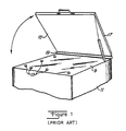
- FIG. 1 there is shown a pictorial representation of a conventional light box commonly used in contact printing processes to expose an actinically-sensitive copy sheet and a master sheet of artwork to a source of radiation (e.g. light).
- a master sheet and a copy sheet maybe held together in precise registration upon a transparent or translucent glass plate 9 while exposed to a source of light (not shown) within the supporting box 11.
- registration pins 13 may be provided on or about the plate to mate with holes in the registered sheets. It is common practice to overlay the registered sheets with an impervious rubber blanket 15 that forms an air-tight seal around the perimeter of the glass plate.
- Residual air remaining between the sheets and under the blanket can then be evacuated via apertures through, or around the perimeter of, the glass plate 9 by pumping equipment that is housed within the supporting box 11.
- the pressure differential thus established across the blanket produces a well distributed force that squeezes the registered sheets together and against the glass plate 9. This assures that the sheets are held flat against the glass plate 9 against relative movement during the exposure to light through the glass plate 9.
- the conventional apparatus of Figure 1 supports the rubber blanket in a lid-like cover 17 that is hinged 19 to the rear edge of box 11. This arrangement inhibits clear access to the glass plate from all sides for purposes of inspection of sheets on the plate, cleaning of the plate, and the like.
- FIG 2 there is shown a conventional light box 12 that houses the light source, vacuum pump, control circuitry, and the like (not illustrated), and that includes a transparent or translucent glass plate 14 on the top surface through which the desired light exposure is accomplished. Registration pins 16 are provided on the glass plate 14 to facilitate the precise registration of master and copy sheets that are positioned on the plate for exposure.
- An impervious blanket 18 is rolled upon a spring-wound roller 20 which, in turn, is mounted at its ends for rotation within housing 22.
- Housing 22 is disposed to move back and forth 24 from side to side (or from front to rear) along tracks 26 that are positioned near the forward and rearward edges of the plate 14.
- Drive motors and controls for moving the housing 22 along the tracks 26 are also contained within housing 22 and may be connected to the box 12 through a sufficient length of cable.
- the outer, lateral edge 28 of the rolled blanket 18 is secured to the upper surface of the box 12 near one side edge to facilitate the unrolling of the blanket 18 off the roller 20 as the housing 22, roller 20, and rolled blanket 18 travel toward the opposite side edge 30.
- the blanket 18 is rolled out flat over the glass plate 14 (and over sheets positioned thereon) and forms an air-tight seal about the perimeter thereof.
- a vacuum pump within the box 12 (not shown) then evacuates the air remaining under the blanket 18 via apertures 32 located around the glass plate within the boundary of the air-tight seal formed by the blanket 18.
- the housing 22 and roller 20 travel along tracks 26 back to the initial position illustrated, and in doing so, re-roll the blanket 18 off the surface of the plate 14.
- a light box 21 with a transparent or translucent glass plate 23 positioned in the upper surface.
- Registration pins 25 are positioned near the front edge to facilitate precise, registered positioning of master and copy sheets upon the plate 23.
- the housing 31 includes the blanket 27 rolled upon a spring-wound roller, but with the outer, lateral edge of the blanket projecting forward and not secured to the upper surface of the box 21.
- the housing is disposed to travel in the rearward-forward orientation along tracks 35 that are positioned along opposite sides of the plate 23.
- the housing 31 with rolled blanket 27 travels 33 to the front edge of the plate 23 and box 21 where the outer, lateral edge of the rolled blanket 27 is latched 41 into position, in the manner later described herein, near the forward edge of the plate 23 to facilitate unrolling of blanket over the plate 23, as shown, as the housing 31 travels rearwardly to the idle position illustrated.
- the blanket 27 forms an airtight seal around the perimeter of the plate 23 and residual air can be evacuated from under the blanket 27, as previously described.
- the drive motors and control circuitry for moving housing 31 may be contained within housing 31 and be connected to the box 21 through a cable of sufficient length.
- the housing 31 After pumping air from under the blanket 27 and exposing the registered sheets to light through the plate 23, the housing 31 is controlled to move toward the forward edge from its idle position in order to re-roll blanket 27 onto spring-wound roller 29. At the forward edge, the corresponding edge of the blanket 27 is released, as later described, and the housing 31 with rolled blanket 27 moves back to its idle position beyond the rear edge of plate 23.
- the housing 31 may be mounted for travel in the side-to-side orientation, where desired.
- the tracks 35 may include conventional rack gears or stationary chains for mating with corresponding pinion or sprocket gears attached to drive motors in the housing 31.
- the housing 31 with rolled blanket 27 therein may simply be lifted off the box 21 to provide completely unobstructed access to the entire upper surface of the box 21.
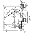
- FIG. 4 there is shown a pictorial sectional view of the preferred embodiment of the travelling housing 31 with the blanket 27 rolled up on roller 29.
- the blanket within the housing 31 passes over an idler roller 48 mounted on pivot axis 50, and a pressure roller 52 mounted on lever 49 to assure that the blanket is properly laid down and picked up as the housing 31 travels back and forth between forward and rearward positions.
- Drive motor 55 is coupled to sprocketed drive wheels 57 via chain 58 for moving the housing 31 back and forth in mating sprocketed tracks 92 while supported by wheels 90 on supporting ways 46.
- the wheels 90 may be captivated on ways 46 by a removable track (not illustrated) which is positioned on top of these wheels to prevent the housing 31 from tipping and to prevent the sprocket wheels 57 from skipping or jumping out of the mating sprocketed tracks 92.
- the forward edge of the vacuum blanket 27 includes a controllable latch mechanism which engages and disengages from the forward edge of the supporting cabinet 60.
- a latch arm 59 is pivotally mounted on shaft 50 for vertical motion under control of solenoid 61 that is coupled 63 to it for picking up and laying down the fixture 65 that is attached to the forward edge of the blanket 27.
- a latch pin 67 mounted on the lever 59 is positioned to engage the notch 69 in release lever 71 when lever 59 is positioned upper position, and to retain the release lever 71 in rearward position (as shown) when lever 59 is in the lower position (as shown).
- Release lever pivots on shaft 73 and is mounted to abut the rear edge 75 of the front edge of the supporting cabinet 60.
- the fixture 65 on the front edge of the blanket 27 includes tabs 77 which drop into the holes 79 in the forward edge of cabinet 60.
- the housing 31 and associated mechanisms described above is driven forward by motor 55 and sprocket 57 toward the forward edge of cabinet 60 from its rest position near the rear edge of the glass exposure plate 80.
- the fixture 65 attached to the forward edge of the blanket 27 is carried by the protruding edge 82 of lever 59 which is held in the upper position by the latch pin 67 that is engaged with the notch 69 in the release lever 71.
- the release lever 71 pivots rearwardy on shaft 73 to disengage the latch pin 67 from notch 69.
- This causes the lever 59 to drop to its lower position, and the fixture 65 with tabs 77 carried thereby drop into the holes 79 in the forward edge of cabinet to secure the forward edge of the blanket 27.
- the housing 31 now travels rearwardly to unwind the blanket 27 from roller 29 into position over the glass plate 80 and gasket 84. Air remaining between the blanket 27 and plate 80 may be evacuated through apertures 86 located around the perimeter of the plate 80, and through associated vacuum ducts 88 beneath the apertures 86 to vacuum pump 94.
- the housing 31 After exposure to light 89 of sheet materials positioned on plate 80 beneath the blanket 27, the housing 31 again is driven forward, this time re-rolling the blanket 27 onto roller 29.
- the re-rolling blanket 27 passes over the idler roller 48 which has a small radius for flexing the blanket 27 to prevent sheet material from adhering to the blanket 27 and being inadvertently rolled up into the housing 31.
- solenoid 61 is controlled to lift the lever 59 with its lower edge 82 engaging fixture 65.
- the tabs 77 are withdrawn from the holes 79 and the latch pin 67 engages notch 69, and the forward edge of the blanket 27 is held in the upper position clear of the plate 80 and the surrounding gasket 84.
- the housing 31 can now be driven rearwardly to its rest position near the rear edge of plate 80.
- the method and means of the present invention conveniently deploy and retract the vacuum blanket over a glass exposure plate to provide unobstructed access to the plate for inspection and cleaning.
Abstract
Description
- This invention relates to photographic light boxes for contact printing, and more specifically to rubber blanket apparatus for retaining close registration between master and copy sheets during light exposure.
- Conventional light boxes for exposing a light-sensitive sheet to a master sheet commonly include an impervious rubber blanket that overlays the stack of sheets to form an air-tight seal against a glass support plate during exposure to light through the glass. A vacuum source evacuates air from between the layers of sheets, glass and blanket with the result that the force of air pressure acting upon the outer surface of the blanket holds the two sheets tightly together in precise registration.
- Various mechanisms have been used to support and deploy such rubber blankets during the operating phases when the sheets are being positioned or removed before and after exposure to light. One known scheme supports the blanket above the glass plate on a movable lid that is hinged along the rear edge of the glass plate. Another known scheme allows a rolled blanket to unroll over the glass plate and sheets to be registered that are placed thereon, and then to re-roll the blanket back to a location near the front working edge of the glass plate after the exposure phase. Residual air remaining between the sheets and under the blanket is evacuated through holes in the glass plate to allow the force of air pressure acting upon the outer surface of the unrolled blanket to hold the master and copy sheets in precise registration.
- One disadvantage of these known schemes is that the light box becomes directionally limited in that it becomes awkward to service or inspect registration of sheets on the glass plate from any edge. In addition, cleaning of the glass plate is impeded by the structure required to support or house the blanket.
- In accordance with the present invention, an improved method and means for deploying a rubber blanket over photographic sheets positioned upon a glass plate includes a mobile blanket roll that is designed to traverse the glass plate along any selected orthogonal axis as the blanket is deployed over the glass plate. More importantly, the mobile blanket roll promotes unobstructed access to the glass plate for cleaning and inspection of registration of sheets positioned upon the plate. Upon command, the mobile roll may be moved over the area of the glass plate to deploy or retrieve the blanket, and thereafter between operating phases may be positioned at a location remote from the glass plate to facilitate clear unobstructed access to the glass plate.
-
- Figure 1 is a pictorial representation of conventional light box apparatus with a hinged lid-like support for the rubber blanket that overlays the glass plate during light exposure; and
- Figure 2 is a pictorial representation of a conventional mobile light box with the blanket apparatus illustrated in idle position; and
- Figures 3 a and b are pictorial representations of an embodiment of the present invention showing mobile apparatus which deploys the blanket with its front edge lockable in position as the blanket is unrolled; and
- Figure 4 is a pictorial sectional view of the mobile apparatus of Figure 3 which illustrates the front edge locking apparatus according to the present invention.
- Referring now to Figure 1, there is shown a pictorial representation of a conventional light box commonly used in contact printing processes to expose an actinically-sensitive copy sheet and a master sheet of artwork to a source of radiation (e.g. light). For example, in diazo-type or photographic contact reproduction process, a master sheet and a copy sheet maybe held together in precise registration upon a transparent or translucent glass plate 9 while exposed to a source of light (not shown) within the supporting
box 11. To facilitate the precise registration of the sheets during exposure, registration pins 13 may be provided on or about the plate to mate with holes in the registered sheets. It is common practice to overlay the registered sheets with animpervious rubber blanket 15 that forms an air-tight seal around the perimeter of the glass plate. Residual air remaining between the sheets and under the blanket can then be evacuated via apertures through, or around the perimeter of, the glass plate 9 by pumping equipment that is housed within the supportingbox 11. The pressure differential thus established across the blanket produces a well distributed force that squeezes the registered sheets together and against the glass plate 9. This assures that the sheets are held flat against the glass plate 9 against relative movement during the exposure to light through the glass plate 9. - After such exposure of the registered sheets, the
rubber blanket 15 must be removed to provide access to the sheets. The conventional apparatus of Figure 1 supports the rubber blanket in a lid-like cover 17 that is hinged 19 to the rear edge ofbox 11. This arrangement inhibits clear access to the glass plate from all sides for purposes of inspection of sheets on the plate, cleaning of the plate, and the like. - In Figure 2, there is shown a conventional light box 12 that houses the light source, vacuum pump, control circuitry, and the like (not illustrated), and that includes a transparent or translucent glass plate 14 on the top surface through which the desired light exposure is accomplished. Registration pins 16 are provided on the glass plate 14 to facilitate the precise registration of master and copy sheets that are positioned on the plate for exposure.
- An
impervious blanket 18 is rolled upon a spring-wound roller 20 which, in turn, is mounted at its ends for rotation withinhousing 22.Housing 22 is disposed to move back and forth 24 from side to side (or from front to rear) alongtracks 26 that are positioned near the forward and rearward edges of the plate 14. Drive motors and controls for moving thehousing 22 along thetracks 26 are also contained withinhousing 22 and may be connected to the box 12 through a sufficient length of cable. The outer,lateral edge 28 of the rolledblanket 18 is secured to the upper surface of the box 12 near one side edge to facilitate the unrolling of theblanket 18 off theroller 20 as thehousing 22,roller 20, and rolledblanket 18 travel toward the opposite side edge 30. At the position 30 of maximum travel, theblanket 18 is rolled out flat over the glass plate 14 (and over sheets positioned thereon) and forms an air-tight seal about the perimeter thereof. A vacuum pump within the box 12 (not shown) then evacuates the air remaining under theblanket 18 via apertures 32 located around the glass plate within the boundary of the air-tight seal formed by theblanket 18. After the requisite light exposure, thehousing 22 androller 20 travel alongtracks 26 back to the initial position illustrated, and in doing so, re-roll theblanket 18 off the surface of the plate 14. - In accordance with the preferred embodiment of the present invention that is illustrated in Figures 3a and 3b, there is shown a
light box 21 with a transparent ortranslucent glass plate 23 positioned in the upper surface.Registration pins 25 are positioned near the front edge to facilitate precise, registered positioning of master and copy sheets upon theplate 23. Thehousing 31 includes theblanket 27 rolled upon a spring-wound roller, but with the outer, lateral edge of the blanket projecting forward and not secured to the upper surface of thebox 21. The housing is disposed to travel in the rearward-forward orientation alongtracks 35 that are positioned along opposite sides of theplate 23. In this embodiment, thehousing 31 with rolledblanket 27travels 33 to the front edge of theplate 23 andbox 21 where the outer, lateral edge of the rolledblanket 27 is latched 41 into position, in the manner later described herein, near the forward edge of theplate 23 to facilitate unrolling of blanket over theplate 23, as shown, as thehousing 31 travels rearwardly to the idle position illustrated. Theblanket 27 forms an airtight seal around the perimeter of theplate 23 and residual air can be evacuated from under theblanket 27, as previously described. Of course, the drive motors and control circuitry for movinghousing 31 may be contained withinhousing 31 and be connected to thebox 21 through a cable of sufficient length. - After pumping air from under the
blanket 27 and exposing the registered sheets to light through theplate 23, thehousing 31 is controlled to move toward the forward edge from its idle position in order to re-rollblanket 27 onto spring-wound roller 29. At the forward edge, the corresponding edge of theblanket 27 is released, as later described, and thehousing 31 with rolledblanket 27 moves back to its idle position beyond the rear edge ofplate 23. Of course, it should be understood that thehousing 31 may be mounted for travel in the side-to-side orientation, where desired. - In each of the embodiments of the present invention that are illustrated in Figures 2 and 3, the
tracks 35 may include conventional rack gears or stationary chains for mating with corresponding pinion or sprocket gears attached to drive motors in thehousing 31. However, in the embodiment of Figure 3, thehousing 31 with rolledblanket 27 therein may simply be lifted off thebox 21 to provide completely unobstructed access to the entire upper surface of thebox 21. - Referring now to Figure 4, there is shown a pictorial sectional view of the preferred embodiment of the
travelling housing 31 with theblanket 27 rolled up onroller 29. The blanket within thehousing 31 passes over anidler roller 48 mounted on pivot axis 50, and apressure roller 52 mounted onlever 49 to assure that the blanket is properly laid down and picked up as thehousing 31 travels back and forth between forward and rearward positions.Drive motor 55 is coupled to sprocketeddrive wheels 57 via chain 58 for moving thehousing 31 back and forth in mating sprocketed tracks 92 while supported bywheels 90 on supportingways 46. Thewheels 90 may be captivated onways 46 by a removable track (not illustrated) which is positioned on top of these wheels to prevent thehousing 31 from tipping and to prevent thesprocket wheels 57 from skipping or jumping out of the mating sprocketed tracks 92. - In accordance with one embodiment of the present invention, the forward edge of the
vacuum blanket 27 includes a controllable latch mechanism which engages and disengages from the forward edge of the supporting cabinet 60. Briefly, alatch arm 59 is pivotally mounted on shaft 50 for vertical motion under control ofsolenoid 61 that is coupled 63 to it for picking up and laying down thefixture 65 that is attached to the forward edge of theblanket 27. Alatch pin 67 mounted on thelever 59 is positioned to engage thenotch 69 inrelease lever 71 whenlever 59 is positioned upper position, and to retain therelease lever 71 in rearward position (as shown) whenlever 59 is in the lower position (as shown). Release lever pivots onshaft 73 and is mounted to abut therear edge 75 of the front edge of the supporting cabinet 60. Thefixture 65 on the front edge of theblanket 27 includes tabs 77 which drop into the holes 79 in the forward edge of cabinet 60. - In operation, the
housing 31 and associated mechanisms described above is driven forward bymotor 55 and sprocket 57 toward the forward edge of cabinet 60 from its rest position near the rear edge of theglass exposure plate 80. Thefixture 65 attached to the forward edge of theblanket 27 is carried by theprotruding edge 82 oflever 59 which is held in the upper position by thelatch pin 67 that is engaged with thenotch 69 in therelease lever 71. As the release lever 71 abuts therear edge 75 of the forward edge, the release lever 71 pivots rearwardy onshaft 73 to disengage thelatch pin 67 fromnotch 69. This causes thelever 59 to drop to its lower position, and thefixture 65 with tabs 77 carried thereby drop into the holes 79 in the forward edge of cabinet to secure the forward edge of theblanket 27. - The
housing 31 now travels rearwardly to unwind theblanket 27 fromroller 29 into position over theglass plate 80 and gasket 84. Air remaining between theblanket 27 andplate 80 may be evacuated throughapertures 86 located around the perimeter of theplate 80, and through associatedvacuum ducts 88 beneath theapertures 86 tovacuum pump 94. - After exposure to light 89 of sheet materials positioned on
plate 80 beneath theblanket 27, thehousing 31 again is driven forward, this time re-rolling theblanket 27 ontoroller 29. There-rolling blanket 27 passes over theidler roller 48 which has a small radius for flexing theblanket 27 to prevent sheet material from adhering to theblanket 27 and being inadvertently rolled up into thehousing 31. - As the lower edge of
release lever 71 abuts thecabinet 75,solenoid 61 is controlled to lift thelever 59 with itslower edge 82 engagingfixture 65. The tabs 77 are withdrawn from the holes 79 and thelatch pin 67 engagesnotch 69, and the forward edge of theblanket 27 is held in the upper position clear of theplate 80 and the surroundinggasket 84. Thehousing 31 can now be driven rearwardly to its rest position near the rear edge ofplate 80. - Therefore, the method and means of the present invention conveniently deploy and retract the vacuum blanket over a glass exposure plate to provide unobstructed access to the plate for inspection and cleaning.
- The features disclosed in the foregoing description, in the claims and/or in the accompanying drawings may, both separately and in any combination thereof, be material for realising the invention in diverse forms thereof.
Claims (5)
the housing (31) moves between one location near an edge of the exposure plate (23) and a remote location near another edge of the exposure plate opposite the one location;
a latch (59, 65, 77, 79) operates on an edge of the sheet (27) to selectively fix the edge of the sheet near an edge of the exposure plate (80) at one location as the sheet material is deployed over the exposure plate during movement of the housing (31) toward the other location, and to release said edge at the one location after retrieving the sheet material into the hosuing during movement thereof from the other location toward said one location;
a controller moves the housing (31) bidirectionally across the exposure plate (80) between said locations for sequentially transporting the sheet material (27) and said edge thereof from the remote location to said one location, and for deploying the sheet material over the exposure plate (80) during motion of the housing in one direction away from said one location, and to retrieve the sheet material into the housing during motion thereof in the opposite directon toward said one location, and for transporting the sheet material and said edge thereof from the one location to the remote location.
the latch includes a lever (59) mounted within the housing for movement between raised and lowered positions in a direction substantially normal to the plane of movement of the housing (31) over the exposure date;
the lever (59) being disposed to selectively engage said edge of the sheet material (27) for controllably lowering and raising said edge; and in that an actuator (61) is mounted within the housing (31) for raising and lowering the lever (59).
the roll of sheet (27) and an edge thereof are selectively moved over the exposure plate (80):
the edge of the sheet is selectively fixed against movement near one boundary of the exposure plate:
the sheet is selectively deployed relative to the fixed edge thereof in response to movement of the roll over the exposure plate in a direction away from the fixed edge;
the sheet is selectively retrieved onto the roll in response to movement of the roll over the exposure plate in a direction toward the fixed edge;
releasing the edge of the sheet is released for movement; and
the roll of sheet and the edge therof are moved over the exposure plate in a direction away from said one boundary.
Applications Claiming Priority (2)
| Application Number | Priority Date | Filing Date | Title |
|---|---|---|---|
| US902148 | 1986-08-29 | ||
| US06/902,148 US4707125A (en) | 1986-08-29 | 1986-08-29 | Photographic registration apparatus and method |
Publications (2)
| Publication Number | Publication Date |
|---|---|
| EP0257529A2 true EP0257529A2 (en) | 1988-03-02 |
| EP0257529A3 EP0257529A3 (en) | 1989-07-19 |
Family
ID=25415375
Family Applications (1)
| Application Number | Title | Priority Date | Filing Date |
|---|---|---|---|
| EP87111989A Withdrawn EP0257529A3 (en) | 1986-08-29 | 1987-08-18 | Apparatus and method for optical radiation exposure |
Country Status (3)
| Country | Link |
|---|---|
| US (1) | US4707125A (en) |
| EP (1) | EP0257529A3 (en) |
| JP (1) | JPS6373230A (en) |
Families Citing this family (11)
| Publication number | Priority date | Publication date | Assignee | Title |
|---|---|---|---|---|
| JPS6398645A (en) * | 1986-10-16 | 1988-04-30 | Dainippon Screen Mfg Co Ltd | Positioning and holding device for photosensitive material |
| US4812883A (en) * | 1987-12-10 | 1989-03-14 | Ernest Ohlig | Graphic material registration apparatus and method |
| US4916484A (en) * | 1987-12-10 | 1990-04-10 | Ernest Ohlig | Graphic material registration apparatus and method |
| US4962405A (en) * | 1989-11-17 | 1990-10-09 | Eastman Kodak Company | Compact contact printer with a flexible transparent cover sheet |
| US4949122A (en) * | 1989-11-17 | 1990-08-14 | Eastman Kodak Company | Contact printer for exposing sensitized graphic art film and paper |
| US4952973A (en) * | 1989-11-17 | 1990-08-28 | Eastman Kodak Company | Removable cover sheet roll for a contact printer |
| US5006889A (en) * | 1990-05-25 | 1991-04-09 | Ernest Ohlig | Graphic material registration apparatus and method and vacuum hold down apparatus therefor |
| JPH04101149A (en) * | 1990-08-20 | 1992-04-02 | Dainippon Screen Mfg Co Ltd | Airtight sheet taking-up and developing mechanism |
| US5298940A (en) * | 1993-01-28 | 1994-03-29 | Ohlig Albert H | Rapid vacuum hold down system and method |
| US7216587B2 (en) * | 2001-05-17 | 2007-05-15 | Day International, Inc. | Method of dispensing metal-backed printing blankets |
| US6540076B1 (en) * | 2001-05-17 | 2003-04-01 | Day International, Inc. | Dispensing carton for metal-backed printing blanket |
Citations (2)
| Publication number | Priority date | Publication date | Assignee | Title |
|---|---|---|---|---|
| DE2549989B2 (en) * | 1975-09-02 | 1979-03-15 | Dainippon Screen Seizo K.K., Kyoto (Japan) | Contact copier » |
| US4437759A (en) * | 1981-09-17 | 1984-03-20 | Dainippon Screen Seizo Kabushiki Kaisha | Contact printer |
-
1986
- 1986-08-29 US US06/902,148 patent/US4707125A/en not_active Expired - Fee Related
-
1987
- 1987-08-18 EP EP87111989A patent/EP0257529A3/en not_active Withdrawn
- 1987-08-27 JP JP62214112A patent/JPS6373230A/en active Pending
Patent Citations (2)
| Publication number | Priority date | Publication date | Assignee | Title |
|---|---|---|---|---|
| DE2549989B2 (en) * | 1975-09-02 | 1979-03-15 | Dainippon Screen Seizo K.K., Kyoto (Japan) | Contact copier » |
| US4437759A (en) * | 1981-09-17 | 1984-03-20 | Dainippon Screen Seizo Kabushiki Kaisha | Contact printer |
Also Published As
| Publication number | Publication date |
|---|---|
| JPS6373230A (en) | 1988-04-02 |
| EP0257529A3 (en) | 1989-07-19 |
| US4707125A (en) | 1987-11-17 |
Similar Documents
| Publication | Publication Date | Title |
|---|---|---|
| US4707125A (en) | Photographic registration apparatus and method | |
| US4796061A (en) | Device for detachably attaching a film onto a drum in a drum type picture scanning recording apparatus | |
| US6904844B2 (en) | Printing plate removing/supplying device | |
| JPS6228453B2 (en) | ||
| US4547066A (en) | Exposure apparatus | |
| JP2696029B2 (en) | Photo plotter media sheet handling equipment | |
| EP0901037B1 (en) | Method of loading film roll on film unwinder shaft and film producing and packaging system | |
| EP0708048B1 (en) | Method and apparatus for installing a media supply cassette in an imagesetter | |
| US4540167A (en) | Apparatus for mounting a recording medium | |
| JP2679968B2 (en) | Photosensitive medium supply and transport system | |
| JPH0468612B2 (en) | ||
| US5207413A (en) | Vacuum sheet film transport and method | |
| US5484139A (en) | System for handling curved form media and cassette therefor | |
| US4529300A (en) | Magazine device with suction boxes | |
| JPH05901Y2 (en) | ||
| DK166469B1 (en) | CONTACT COPY UNIT | |
| EP0702262A1 (en) | Self-contained film exposing/developing machine | |
| JP3105217B1 (en) | Plate making equipment | |
| JP2604523B2 (en) | Automatic color proofing device | |
| JP3327678B2 (en) | Color proof production equipment | |
| JPH0446276Y2 (en) | ||
| JPH0843941A (en) | Projection device and reader printer | |
| JPH09127704A (en) | Sheet-like member carrying device and printing device using it | |
| GB2315339A (en) | Light-tight sheet supply cassette | |
| JPH01503738A (en) | Camera system combined with vacuum feeding and holding assembly |
Legal Events
| Date | Code | Title | Description |
|---|---|---|---|
| PUAI | Public reference made under article 153(3) epc to a published international application that has entered the european phase |
Free format text: ORIGINAL CODE: 0009012 |
|
| AK | Designated contracting states |
Kind code of ref document: A2 Designated state(s): AT BE CH DE ES FR GB GR IT LI LU NL SE |
|
| PUAL | Search report despatched |
Free format text: ORIGINAL CODE: 0009013 |
|
| AK | Designated contracting states |
Kind code of ref document: A3 Designated state(s): AT BE CH DE ES FR GB GR IT LI LU NL SE |
|
| 17P | Request for examination filed |
Effective date: 19891124 |
|
| STAA | Information on the status of an ep patent application or granted ep patent |
Free format text: STATUS: THE APPLICATION IS DEEMED TO BE WITHDRAWN |
|
| 18D | Application deemed to be withdrawn |
Effective date: 19910301 |
|
| RIN1 | Information on inventor provided before grant (corrected) |
Inventor name: OHLIG, ERNEST Inventor name: SLOOP, CONRAD B. |