EP0257370A2 - Folding table - Google Patents
Folding table Download PDFInfo
- Publication number
- EP0257370A2 EP0257370A2 EP87111219A EP87111219A EP0257370A2 EP 0257370 A2 EP0257370 A2 EP 0257370A2 EP 87111219 A EP87111219 A EP 87111219A EP 87111219 A EP87111219 A EP 87111219A EP 0257370 A2 EP0257370 A2 EP 0257370A2
- Authority
- EP
- European Patent Office
- Prior art keywords
- panels
- articulated
- vertical
- condition
- axis
- Prior art date
- Legal status (The legal status is an assumption and is not a legal conclusion. Google has not performed a legal analysis and makes no representation as to the accuracy of the status listed.)
- Granted
Links
Images


Classifications
-
- A—HUMAN NECESSITIES
- A47—FURNITURE; DOMESTIC ARTICLES OR APPLIANCES; COFFEE MILLS; SPICE MILLS; SUCTION CLEANERS IN GENERAL
- A47B—TABLES; DESKS; OFFICE FURNITURE; CABINETS; DRAWERS; GENERAL DETAILS OF FURNITURE
- A47B3/00—Folding or stowable tables
-
- A—HUMAN NECESSITIES
- A47—FURNITURE; DOMESTIC ARTICLES OR APPLIANCES; COFFEE MILLS; SPICE MILLS; SUCTION CLEANERS IN GENERAL
- A47B—TABLES; DESKS; OFFICE FURNITURE; CABINETS; DRAWERS; GENERAL DETAILS OF FURNITURE
- A47B3/00—Folding or stowable tables
- A47B3/08—Folding or stowable tables with legs pivoted to top or underframe
- A47B3/083—Folding or stowable tables with legs pivoted to top or underframe with foldable top leaves
- A47B2003/0835—Folding or stowable tables with legs pivoted to top or underframe with foldable top leaves being superimposed, hinged and foldable
-
- A—HUMAN NECESSITIES
- A47—FURNITURE; DOMESTIC ARTICLES OR APPLIANCES; COFFEE MILLS; SPICE MILLS; SUCTION CLEANERS IN GENERAL
- A47B—TABLES; DESKS; OFFICE FURNITURE; CABINETS; DRAWERS; GENERAL DETAILS OF FURNITURE
- A47B2220/00—General furniture construction, e.g. fittings
- A47B2220/008—General furniture construction, e.g. fittings characterised by materials
- A47B2220/0083—Furniture made of sheet material
Definitions
- the present invention relates to folding tables.
- the object of the invention is to produce a folding table with can be converted from its condition of use to its folded condition and vice versa by simple and rapid operations, which is compact in the folded condition, and which has a relatively simple and reliable structure.
- the principal characteristic of the table according to the invention lies in the fact that its structure is constituted by a plurality of mutually-articulated panels which can be unfolded in an arc of a circle about an axis corresponding to the central vertical axis of the table, from a folded configuration in which the structure is flattened in a plane containing this axis.
- the structure of the table comprises a first series of mutually- articulated panels which define the table-top and a second series of mutually-articulated panels which define a support structure for the table-top, the panels defining the table-top being further articulated alternately to the panels defining the support structure.
- the panels defining the table-top are substantially in the shape of circular sectors and the panels defining the support structure for the table-top are arranged in planes containing the central vertical axis of the table and are articulated together adjacent this axis, the upper edge of each of these panels being articulated to the common edge of a respective pair of panels of the table-top whose upper surfaces come into contact with each other in the folded condition of the table.
- each pair of panels of the support structure is provided with a pair of auxiliary panels which are hinged together and have their opposite sides articulated to the two respective panels of the support structure, the auxiliary panels having upper edges which, in the condition of use of the table, constitute a supporting surface for the two overlying table-top panels whose lower surfaces come into contact with each other in the folded condition of the table.
- the structure of the table can be converted easily and rapidly from its condition of use to its folded condition and vice versa.
- the change from one condition to the other takes place by means of a single operation without the need for assembling or disassembling auxiliary parts.
- the table assumes a compact configuration.
- the structure described above is simple and economical to construct and is highly reliable.
- a further advantage of the table according to the invention lies in the fact that it is also arranged to assume an intermediate configuration between the completely folded condition and the condition of normal use, so that it can be positioned in a corner formed by two walls (the table-top corresponding to a circular sector having an angle of opening of 90°) or against a wall (the table-top corresponding to a circular sector having an angle of opening of 180°).
- an auxiliary panel interposed between each pair of adjacent vertical panels is connected in an articulated manner to the vertical panels adjacent the vertical axis of the table and has an upper edge which supports - in the unfolded condition of the table - a respective pair of table-top panels whose lower surfaces come into contact with each other in the folded condition of the table.
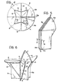
- FIGS 1-17 illustrate a folding table 1 which, in the configuration of normal use ( Figure 1), has a table-top 2 and a structure 3 for supporting the table-top 2.
- the table-top 2 consists of a plurality of panels 4 in the form of circular sectors having radial sides converging towards the central vertical axis of the table, indicated 5.
- the example illustrated relates to the case in which the external circumferences of the sector-shaped panels 4 are arranged in a single circumference having its centre on the axis 5, so that the table-top is circular in the unfolded condition of the table illustrated in Figure 1.
- the panels 4 could be shaped so that, in the unfolded condition of the table, they would form a table-top of different shape, for example, square, rectangular, or oval.
- All the panels 4 of the table-top 2 are articulated together like an accordion at their contiguous radial sides, with the exception of the two panels indicated 4a in Figure 1. These panels 4a are not connected to each other, but only to the two respective panels 4 next to them.
- the structure of the table-top 2 can therefore be folded like an accordion, starting from the configuration illustrated in Figure 1, by means of a circular arcuate movement about the axis 5. During this movement, the two panels 4a move progressively away from each other.
- the articulations between the panels 4 and 4a are alternately indicated 6, 7 in Figure 1. In the folded condition of the table (see Figures 9, 5), the upper surfaces of the two panels 4 adjacent each articulation 6 are in contact with each other, while the lower surfaces of the two panels adjacent each articulation 7 are in contact with each other.
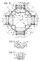
- the structure 3 for supporting the table-top 2 comprises a plurality of vertical panels 8 articulated together adjacent the central axis 5 of the table and arranged in meridian planes relative to this axis. Two of these panels, indicated 8a in the drawings, are not connected to each other, but only to the two respective panels 8 next to them. With the table in the unfolded condition, the two panels 8a are beside each other and the pair of panels 8a and the three further panels 8 are disposed at 90° to each other (see Figures 4, 10).
- the thickness of each of the panels 8a preferably corresponds to half the thickness of the panels 8 so that, in the condition of normal use of the table, the support structure 3 appears to consist of four panels of equal thickness located at 90° to each other.
- each pair of adjacent vertical panels of the structure 3 is provided with a further pair of triangular auxiliary panels 9 which are hinged together at a common edge 10 and have their opposite edges 11 articulated to the two respective panels 8.
- the two panels 8a are an exception, of course, no pair of auxiliary panels 9 being provided between them since the panels 8a must be completely separable from each other to enable the table to be folded.
- the upper edges of the auxiliary panels 9, indicated 12, constitute a supporting surface for the two panels 4 immediately above. The stability of the table-top 2 is thus ensured in the configuration of normal use of the table.
- FIGS. 10 to 17 of the appended drawings illustrate in detail the structural details of the table described above in a preferred embodiment. It is clear that these structural details could also be varied, without thereby departing from the scope of the invention.
- each articulation 13 is achieved by means of a conventional metal hinge 14 consisting of two hinge elements 15 forming holes in which an articulation pin is engaged and extending for the entire height of the panels 8, 8a.
- the two hinge elements 15 of each hinge 14 have lateral flanges 16 which are fixed to the respective panels 8, 8a by means of rivets 17.
- a shaped element 18 of deformable elastomeric material is associated with each hinge 14 and also has longitudinal flanges, indicated 19, fixed to the respective panels 8, 8a by means of the rivets 17.
- Figure 11 illustrates the detail of Figure 10 in the folded condition of the table, with the elements 18 in their deformed condition.
- FIG 12 illustrates in section the detail of the articulation 6 between two contiguous panels 4 of the table-top.
- the articulation 6 between the two panels is actually achieved by a pair of hinges 20, by means of which the two panels 4 are respectively articulated to the respective panel 8 of the support structure 3 about two parallel axes 21.
- Each of the two hinges 20 comprises two sheet-metal hinge elements 22 having flanges inserted in channels 23 formed in the panels 4 and 8. Holes 24 are also formed in these panels to provide access for a tool intended to be pressed against the flanges 22 to deform them and prevent the flanges from coming out of the channels 23.
- FIG 13 shows the connection of the two auxiliary panels 9 associated with a panel 8 of the support structure 3.
- Each panel 9 is articulated to the panel 8 about an axis 25 by means of a metal hinge 26 having a hinge element 27 connected to the panel 8 and a hinge element 28 connected to the panel 9, in a manner similar to that illustrated for the elements for the elements 22 of Figure 12.
- the two hinge elements 27 associated with the panel 8 are connected together by means of a screw 29 which engages two cup-shaped appendages 30 inserted in a through-hole 31 whose ends are closed by two elements 32 of plastics material.
- Figures 14 and 15 are sections showing the articulation 7 between two panels 4 of the table top in the condition of normal use and in the folded condition of the table respectively.
- This articulation achieved by means of a hinge 33, comprises two sheet-metal hinge elements 34 having flanges 35 inserted in holes 36 formed in the panels 4.
- Each flange 35 is provided with a lip 37 which is engaged in the body of the panel. This engagement occurs as a result of the insertion into each of the holes 36 of a plastics body 38 which causes deformation of the flange 35 from the undeformed condition illustrated by broken lines on the right-hand side of Figure 14.
- Figures 16 and 17 illustrate in section, in the extended and folded section respectively, the mutual articulation of two auxiliary panels 9, which is achieved by means of a sheet of deformable elastomeric material 39 having longitudinal edges fixed in channels 40 formed in the panels 9.
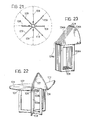
- FIGS 18 to 31 of the appended drawings illustrate a second embodiment of the table according to the invention.
- the parts common or corresponding to those of Figures 1-17 are indicated with the same reference numerals increased by 100.
- each panel 108 has a frame structure consisting of metal box-section members.
- a further difference lies in the fact that, in order to ensure the necessary support for the panels 104 of the table-top at the hinges 107 when the table is in the condition of normal use, an auxiliary panel 109 is interposed between each pair of adjacent vertical panels 108.
- this panel is right-angled and has a vertical arm 109a articulated to the respective pair of vertical panels 108 adjacent the axis 105 of the table and a horizontal arm 109b for supporting the two panels 104 immediately above.
- each panel 108 is provided at the opposite ends of its inner vertical arm (the drawings illustrate only the uppr end) with a reinforcing plate 110 which is welded to the structure of the panel and has two circular holes 111 with vertical axes.
- a plate-shaped hinge element 113 is fixed to each plate 110 by means of screws (not illustrated) which engage holes 112, and has a T-shaped head 114 with two holes 115 which are aligned with the two holes 111.
- each intermediate panel 109 is provided at the upper and the lower ends of its vertical arm 109a with a reinforcing plate 116 on which is fixed a hinge element 117, also plate-shaped, fixed to the plate 116 by means of screws (not illustrated) which engage holes 118.
- the plate 117 has a T-shaped head 119 with holes 120.
- the hinge elements 113, 117 are articulated to each other by means of articulation pins 121 which engage the aligned holes.
- Each pin 121 has an enlarged head which rests on the respective head 119 and is held in position axially by means of circlips 122.
- the structure of the panels 108, 109 consists of metal box-sections welded together.
- the connection between the upper arm 109b and the lower arm 109a is further stiffened by means of an internal connecting element 123 welded to both arms of the panel.
- Figure 26 illustrates the connection of a panel 108 to the respective hinge 106.
- an element 125 is fixed to the upper edge of each panel 108 by means of screws 126 and has two arms 127.
- the respective panels 104 of the table-top are provided with metal plates 129 fixed by means of screws 130 and articulated at 128 to the two arms 127.
- the part 125 is provided with a single arm 127 having a symmetrical configuration with respect to that of the part 125 of the other panel 108a.
- Figure 27 illustrates the structure of Figure 26 in the folded condition of the table.
- the two hinge elements consist of two metal plates 131 fixed to the panels 104 by means of screws 132.
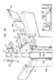
- each intermediate panel 109 is provided at its outer end with an element 135, for example of plastics material, for supporting the overlying panels of the table-top.
- the lower arm of each panel 108 is provided at its outer end with a supporting foot 136, for example of plastics material, and at its inner end with a wheel 137 which, however, is not in contact with the floor when the table is open with the feet 136 resting on the floor.
- the flattened unit thus obtained rests both on its feet 136, which are side by side, and on the wheels 137, enabling the folded table to be moved easily.
Abstract

Description
- The present invention relates to folding tables.
- The object of the invention is to produce a folding table with can be converted from its condition of use to its folded condition and vice versa by simple and rapid operations, which is compact in the folded condition, and which has a relatively simple and reliable structure.
- The principal characteristic of the table according to the invention lies in the fact that its structure is constituted by a plurality of mutually-articulated panels which can be unfolded in an arc of a circle about an axis corresponding to the central vertical axis of the table, from a folded configuration in which the structure is flattened in a plane containing this axis.
- According to a further characteristic, the structure of the table comprises a first series of mutually- articulated panels which define the table-top and a second series of mutually-articulated panels which define a support structure for the table-top, the panels defining the table-top being further articulated alternately to the panels defining the support structure.
- In a preferred embodiment, the panels defining the table-top are substantially in the shape of circular sectors and the panels defining the support structure for the table-top are arranged in planes containing the central vertical axis of the table and are articulated together adjacent this axis, the upper edge of each of these panels being articulated to the common edge of a respective pair of panels of the table-top whose upper surfaces come into contact with each other in the folded condition of the table. In a first embodiment, each pair of panels of the support structure is provided with a pair of auxiliary panels which are hinged together and have their opposite sides articulated to the two respective panels of the support structure, the auxiliary panels having upper edges which, in the condition of use of the table, constitute a supporting surface for the two overlying table-top panels whose lower surfaces come into contact with each other in the folded condition of the table.
- By virtue of these characteristics, the structure of the table can be converted easily and rapidly from its condition of use to its folded condition and vice versa. In practice, the change from one condition to the other takes place by means of a single operation without the need for assembling or disassembling auxiliary parts. In the folded condition, the table assumes a compact configuration. Furthermore, the structure described above is simple and economical to construct and is highly reliable.
- A further advantage of the table according to the invention lies in the fact that it is also arranged to assume an intermediate configuration between the completely folded condition and the condition of normal use, so that it can be positioned in a corner formed by two walls (the table-top corresponding to a circular sector having an angle of opening of 90°) or against a wall (the table-top corresponding to a circular sector having an angle of opening of 180°).
- In a second embodiment, an auxiliary panel interposed between each pair of adjacent vertical panels is connected in an articulated manner to the vertical panels adjacent the vertical axis of the table and has an upper edge which supports - in the unfolded condition of the table - a respective pair of table-top panels whose lower surfaces come into contact with each other in the folded condition of the table.
- Further characteristics and advantages of the invention will become clear from the description which follows with reference to the appended drawings, provided purely by way of non-limiting example, in which:
- Figure 1 is a perspective view of a first embodiment of the invention, in the condition of normal use of the table,
- Figure 2, 3 and 4 illustrate a side elevational view, a plan view and a view from below of the table of Figure 1,
- Figure 5 shows the table of Figure 1 in the completely folded condition,
- Figures 6, 7, 8 and 9 are perspective views which show four intermediate configurations which the table assumes successively when it is converted from the configuration of normal use of Figure 1 to the completely folded configuration of Figure 5,
- Figure 10 is a section taken on the line X-X of Figure 2, on an enlarged scale,
- Figure 11 is a section taken on the line XI-XI of Figure 5, on an enlarged scale,
- Figure 12 is a section taken on the line XII-XII of Figure 3, on an enlarged scale,
- Figure 13 is a section taken on the line XIII-XIII of Figure 1, on an enlarged scale,
- Figure 14 is a section taken on the line XIV-XIV of Figure 3, on an enlarged scale,
- Figure 15 shows the detail of Figure 14 in the folded condition of the table,
- Figure 16 is a section taken on the line XVI-XVI of Figure 2, on an enlarged scale,
- Figure 17 shows the detail of Figure 16 in the folded condition of the table,
- Figure 18 is a perspective view of the table according to the invention in the condition of use,
- Figures 19 to 21 respectively are an elevational view, a plan view and a view from below of the table of Figure 18 in the condition of use.
- Figure 22 is a perspective view of the table of Figure 18 in a partially folded condition,
- Figure 23 is a perspective view of the table in the completely folded condition,
- Figure 24 is a detail of Figure 21 on an enlarged scale,
- Figure 25 shows the detail of Figure 24 in the folded condition of the table,
- Figure 26 is a section taken on the line XXVI of Figure 18,
- Figure 27 shows the detail of Figure 26 in the folded condition of the table,
- Figure 28 is a section taken on the line XXVIII of Figure 18,
- Figure 29 shows the detail of Figure 28 in the folded condition of the table,
- Figure 30 is an exploded perspective view of the detail shown in Figure 24, and
- Figure 31 shows the detail XXXI of Figure 19.
- Figures 1-17 illustrate a folding table 1 which, in the configuration of normal use (Figure 1), has a table-top 2 and a structure 3 for supporting the table-top 2. The table-top 2 consists of a plurality of
panels 4 in the form of circular sectors having radial sides converging towards the central vertical axis of the table, indicated 5. The example illustrated relates to the case in which the external circumferences of the sector-shaped panels 4 are arranged in a single circumference having its centre on theaxis 5, so that the table-top is circular in the unfolded condition of the table illustrated in Figure 1. However, it is clear that thepanels 4 could be shaped so that, in the unfolded condition of the table, they would form a table-top of different shape, for example, square, rectangular, or oval. All thepanels 4 of the table-top 2 are articulated together like an accordion at their contiguous radial sides, with the exception of the two panels indicated 4a in Figure 1. Thesepanels 4a are not connected to each other, but only to the tworespective panels 4 next to them. The structure of the table-top 2 can therefore be folded like an accordion, starting from the configuration illustrated in Figure 1, by means of a circular arcuate movement about theaxis 5. During this movement, the twopanels 4a move progressively away from each other. The articulations between thepanels panels 4 adjacent eacharticulation 6 are in contact with each other, while the lower surfaces of the two panels adjacent eacharticulation 7 are in contact with each other. - The structure 3 for supporting the table-top 2 comprises a plurality of
vertical panels 8 articulated together adjacent thecentral axis 5 of the table and arranged in meridian planes relative to this axis. Two of these panels, indicated 8a in the drawings, are not connected to each other, but only to the tworespective panels 8 next to them. With the table in the unfolded condition, the twopanels 8a are beside each other and the pair ofpanels 8a and the threefurther panels 8 are disposed at 90° to each other (see Figures 4, 10). The thickness of each of thepanels 8a preferably corresponds to half the thickness of thepanels 8 so that, in the condition of normal use of the table, the support structure 3 appears to consist of four panels of equal thickness located at 90° to each other. - The upper edges of the three
vertical panels 8 are articulated to the threehinges 6 of the table-top, while the upper edges of the twopanels 8a are articulated to the free radial edges of the twopanels 4a. As a result of this structure and arrangement, when the table-top is folded like an accordion from its condition of normal use, the panels of the support structure 3 rotate about their respective articulations adjacent thevertical axis 5 of the table and are brought into the condition illustrated in Figure 5, in which they are side by side. This movement occurs naturally as theend panels 8a move progressively apart. - In order to ensure the necessary support of the
panels 4 of the table-top at thehinges 7, when the table is in the unfolded condition, each pair of adjacent vertical panels of the structure 3 is provided with a further pair of triangularauxiliary panels 9 which are hinged together at acommon edge 10 and have theiropposite edges 11 articulated to the tworespective panels 8. The twopanels 8a are an exception, of course, no pair ofauxiliary panels 9 being provided between them since thepanels 8a must be completely separable from each other to enable the table to be folded. With the table in the configuration of normal use, the upper edges of theauxiliary panels 9, indicated 12, constitute a supporting surface for the twopanels 4 immediately above. The stability of the table-top 2 is thus ensured in the configuration of normal use of the table. - Figures 10 to 17 of the appended drawings illustrate in detail the structural details of the table described above in a preferred embodiment. It is clear that these structural details could also be varied, without thereby departing from the scope of the invention.
- With reference to Figure 10, the
panels vertical axes 13 equidistant from the centralvertical axis 5 of the table. Eacharticulation 13 is achieved by means of aconventional metal hinge 14 consisting of twohinge elements 15 forming holes in which an articulation pin is engaged and extending for the entire height of thepanels hinge elements 15 of eachhinge 14 havelateral flanges 16 which are fixed to therespective panels rivets 17. In order to conceal themetal hinges 14 from view when the table is in the folded condition, ashaped element 18 of deformable elastomeric material is associated with eachhinge 14 and also has longitudinal flanges, indicated 19, fixed to therespective panels rivets 17. Figure 11 illustrates the detail of Figure 10 in the folded condition of the table, with theelements 18 in their deformed condition. - Figure 12 illustrates in section the detail of the
articulation 6 between twocontiguous panels 4 of the table-top. As can be seen from Figure 12, thearticulation 6 between the two panels is actually achieved by a pair ofhinges 20, by means of which the twopanels 4 are respectively articulated to therespective panel 8 of the support structure 3 about twoparallel axes 21. Each of the two hinges 20 comprises two sheet-metal hinge elements 22 having flanges inserted inchannels 23 formed in thepanels Holes 24 are also formed in these panels to provide access for a tool intended to be pressed against theflanges 22 to deform them and prevent the flanges from coming out of thechannels 23. - Figure 13 shows the connection of the two
auxiliary panels 9 associated with apanel 8 of the support structure 3. Eachpanel 9 is articulated to thepanel 8 about anaxis 25 by means of ametal hinge 26 having ahinge element 27 connected to thepanel 8 and ahinge element 28 connected to thepanel 9, in a manner similar to that illustrated for the elements for theelements 22 of Figure 12. The twohinge elements 27 associated with thepanel 8 are connected together by means of ascrew 29 which engages two cup-shapedappendages 30 inserted in a through-hole 31 whose ends are closed by twoelements 32 of plastics material. - Figures 14 and 15 are sections showing the
articulation 7 between twopanels 4 of the table top in the condition of normal use and in the folded condition of the table respectively. This articulation, achieved by means of ahinge 33, comprises two sheet-metal hinge elements 34 havingflanges 35 inserted inholes 36 formed in thepanels 4. Eachflange 35 is provided with alip 37 which is engaged in the body of the panel. This engagement occurs as a result of the insertion into each of theholes 36 of aplastics body 38 which causes deformation of theflange 35 from the undeformed condition illustrated by broken lines on the right-hand side of Figure 14. - Figures 16 and 17 illustrate in section, in the extended and folded section respectively, the mutual articulation of two
auxiliary panels 9, which is achieved by means of a sheet of deformableelastomeric material 39 having longitudinal edges fixed inchannels 40 formed in thepanels 9. - Figures 18 to 31 of the appended drawings illustrate a second embodiment of the table according to the invention. In this drawing, the parts common or corresponding to those of Figures 1-17 are indicated with the same reference numerals increased by 100.
- A first difference with respect to the table of Figures 1-17 lies in the fact that, while the table-
top 102 preferably consists of wood, eachpanel 108 has a frame structure consisting of metal box-section members. A further difference lies in the fact that, in order to ensure the necessary support for thepanels 104 of the table-top at thehinges 107 when the table is in the condition of normal use, anauxiliary panel 109 is interposed between each pair of adjacentvertical panels 108. In the case of the embodiment illustrated, this panel is right-angled and has avertical arm 109a articulated to the respective pair ofvertical panels 108 adjacent the axis 105 of the table and ahorizontal arm 109b for supporting the twopanels 104 immediately above. - The mutual articulation of the
panels panel 108 is provided at the opposite ends of its inner vertical arm (the drawings illustrate only the uppr end) with a reinforcingplate 110 which is welded to the structure of the panel and has twocircular holes 111 with vertical axes. A plate-shapedhinge element 113 is fixed to eachplate 110 by means of screws (not illustrated) which engageholes 112, and has a T-shapedhead 114 with twoholes 115 which are aligned with the twoholes 111. In its turn, eachintermediate panel 109 is provided at the upper and the lower ends of itsvertical arm 109a with a reinforcingplate 116 on which is fixed ahinge element 117, also plate-shaped, fixed to theplate 116 by means of screws (not illustrated) which engage holes 118. Theplate 117 has a T-shapedhead 119 withholes 120. When the table is in the assembled condition, theheads 119 are partially superimposed on theadjacent heads 114, so that eachhole 120 is aligned with therespective hole 115 of theadjacent head 114. Thehinge elements pin 121 has an enlarged head which rests on therespective head 119 and is held in position axially by means ofcirclips 122. - As seen in Figure 13, the structure of the
panels panels 109, the connection between theupper arm 109b and thelower arm 109a is further stiffened by means of an internal connectingelement 123 welded to both arms of the panel. - Figure 26 illustrates the connection of a
panel 108 to therespective hinge 106. As can be seen, anelement 125 is fixed to the upper edge of eachpanel 108 by means ofscrews 126 and has twoarms 127. Therespective panels 104 of the table-top are provided withmetal plates 129 fixed by means ofscrews 130 and articulated at 128 to the twoarms 127. In the case of eachpanel 108a, thepart 125 is provided with asingle arm 127 having a symmetrical configuration with respect to that of thepart 125 of theother panel 108a. - Figure 27 illustrates the structure of Figure 26 in the folded condition of the table.
- Figure 28 and 29, however, illustrate a
hinge 107 of the twopanels 104 of the table in the open condition and in the folded condition. As can be seen, the two hinge elements consist of twometal plates 131 fixed to thepanels 104 by means ofscrews 132. - With reference to Figure 30, the
upper arm 109b of eachintermediate panel 109 is provided at its outer end with anelement 135, for example of plastics material, for supporting the overlying panels of the table-top. With reference to Figure 31, the lower arm of eachpanel 108 is provided at its outer end with a supportingfoot 136, for example of plastics material, and at its inner end with awheel 137 which, however, is not in contact with the floor when the table is open with thefeet 136 resting on the floor. On the other hand, when the table is folded, as illustrated in Figure 23, the flattened unit thus obtained rests both on itsfeet 136, which are side by side, and on thewheels 137, enabling the folded table to be moved easily.
Claims (11)
Priority Applications (1)
| Application Number | Priority Date | Filing Date | Title |
|---|---|---|---|
| AT87111219T ATE65890T1 (en) | 1986-08-07 | 1987-08-04 | FOLDABLE TABLE. |
Applications Claiming Priority (4)
| Application Number | Priority Date | Filing Date | Title |
|---|---|---|---|
| IT5374186U | 1986-08-07 | ||
| IT5374186U IT208148Z2 (en) | 1986-08-07 | 1986-08-07 | FOLDABLE TABLE |
| IT5349487U IT212306Z2 (en) | 1987-07-01 | 1987-07-01 | FOLDABLE TABLE |
| IT5349487U | 1987-07-01 |
Publications (3)
| Publication Number | Publication Date |
|---|---|
| EP0257370A2 true EP0257370A2 (en) | 1988-03-02 |
| EP0257370A3 EP0257370A3 (en) | 1988-08-24 |
| EP0257370B1 EP0257370B1 (en) | 1991-08-07 |
Family
ID=26329570
Family Applications (1)
| Application Number | Title | Priority Date | Filing Date |
|---|---|---|---|
| EP87111219A Expired - Lifetime EP0257370B1 (en) | 1986-08-07 | 1987-08-04 | Folding table |
Country Status (6)
| Country | Link |
|---|---|
| US (1) | US4809619A (en) |
| EP (1) | EP0257370B1 (en) |
| AT (1) | ATE65890T1 (en) |
| CA (1) | CA1285597C (en) |
| DE (1) | DE3771960D1 (en) |
| ES (1) | ES2025109B3 (en) |
Cited By (4)
| Publication number | Priority date | Publication date | Assignee | Title |
|---|---|---|---|---|
| WO1991003965A1 (en) * | 1989-09-18 | 1991-04-04 | Giuseppe Baggiani | Furnishing element with foldable panels |
| GB2316605A (en) * | 1996-08-28 | 1998-03-04 | Graham Keith Simmonds | Folding stand |
| GB2369561A (en) * | 2000-07-28 | 2002-06-05 | Asmundsson Oli J | A collapsible article of furniture |
| US10390609B2 (en) * | 2017-01-24 | 2019-08-27 | Nemo Equipment, Inc. | Table top and skirt with foldable legs |
Families Citing this family (14)
| Publication number | Priority date | Publication date | Assignee | Title |
|---|---|---|---|---|
| US6009814A (en) * | 1999-01-19 | 2000-01-04 | Rossi; Luis | Expandable table |
| GB0206668D0 (en) * | 2002-03-21 | 2002-05-01 | Wurley Bird Ltd | Improvements relating to play apparatus |
| US6994032B2 (en) | 2003-04-01 | 2006-02-07 | Century Furniture, Llc. | Expandable table |
| US8661991B2 (en) | 2005-08-16 | 2014-03-04 | Bradley R. Eveleth | Foldable stool or table |
| US7905184B2 (en) * | 2005-08-16 | 2011-03-15 | Eveleth Bradley R | Foldable stool or table |
| US7717045B2 (en) * | 2006-05-08 | 2010-05-18 | Dean Robinson | Folding table |
| WO2008134698A1 (en) * | 2007-04-30 | 2008-11-06 | Ferno-Washington, Inc. | High directional having a configurable number of telescoping legs |
| US7849803B2 (en) | 2007-08-24 | 2010-12-14 | Century Furniture Llc | Expandable table and center alignment assembly for such an expandable table |
| US20130099547A1 (en) * | 2011-10-03 | 2013-04-25 | Leo Paper Bags Manufacturing (1982) Limited | Automatic deployable, foldable furniture system |
| EP3310213B1 (en) * | 2015-06-17 | 2020-05-20 | Studio Gooris Limited | A foldable child booster seat |
| USD808695S1 (en) * | 2015-07-20 | 2018-01-30 | Molo Design, Ltd. | Collapsible table |
| US10070718B2 (en) * | 2015-11-16 | 2018-09-11 | Xiumao TAO | Foldable table |
| US11078698B2 (en) * | 2016-02-01 | 2021-08-03 | Brigham Young University | Non-planar closed-loop hinge mechanism with rolling-contact hinge |
| US10758038B2 (en) | 2018-05-29 | 2020-09-01 | Knoll, Inc. | Article of furniture and method of using the same |
Citations (2)
| Publication number | Priority date | Publication date | Assignee | Title |
|---|---|---|---|---|
| US2604932A (en) * | 1951-02-14 | 1952-07-29 | Henry S Leggett | Collapsible stool or table |
| US4046084A (en) * | 1977-02-22 | 1977-09-06 | Hosford Charles D | Folding stool and table |
Family Cites Families (12)
| Publication number | Priority date | Publication date | Assignee | Title |
|---|---|---|---|---|
| DE220681C (en) * | ||||
| US351101A (en) * | 1886-10-19 | Revolving extension-table | ||
| US340176A (en) * | 1886-04-20 | Simon w | ||
| US726787A (en) * | 1902-02-01 | 1903-04-28 | John E Turner | Folding table. |
| US1040330A (en) * | 1911-06-05 | 1912-10-08 | Art Screen Table Company | Folding table. |
| US2184976A (en) * | 1939-02-20 | 1939-12-26 | Michigan Artcraft Company | Table |
| FR73897E (en) * | 1958-07-30 | 1960-09-12 | Improved hinge, method and equipment for mounting said hinge, and furniture including application | |
| US3303797A (en) * | 1966-01-24 | 1967-02-14 | Mueller Herman | Folding table |
| US3490394A (en) * | 1968-04-03 | 1970-01-20 | James A Perkins | Folding table |
| US3606845A (en) * | 1969-04-21 | 1971-09-21 | Franklin J Hickman | Folding table |
| CA938334A (en) * | 1970-09-19 | 1973-12-11 | Anonima Castelli S.A.S. Di Cesare Castelli And C. | Folding table |
| US3683825A (en) * | 1970-11-23 | 1972-08-15 | Marvin Sheldon | Folding table |
-
1987
- 1987-07-31 US US07/080,338 patent/US4809619A/en not_active Expired - Fee Related
- 1987-08-04 AT AT87111219T patent/ATE65890T1/en active
- 1987-08-04 DE DE87111219T patent/DE3771960D1/en not_active Expired - Fee Related
- 1987-08-04 ES ES87111219T patent/ES2025109B3/en not_active Expired - Lifetime
- 1987-08-04 EP EP87111219A patent/EP0257370B1/en not_active Expired - Lifetime
- 1987-08-06 CA CA000543917A patent/CA1285597C/en not_active Expired - Fee Related
Patent Citations (2)
| Publication number | Priority date | Publication date | Assignee | Title |
|---|---|---|---|---|
| US2604932A (en) * | 1951-02-14 | 1952-07-29 | Henry S Leggett | Collapsible stool or table |
| US4046084A (en) * | 1977-02-22 | 1977-09-06 | Hosford Charles D | Folding stool and table |
Cited By (7)
| Publication number | Priority date | Publication date | Assignee | Title |
|---|---|---|---|---|
| WO1991003965A1 (en) * | 1989-09-18 | 1991-04-04 | Giuseppe Baggiani | Furnishing element with foldable panels |
| US5311826A (en) * | 1989-09-18 | 1994-05-17 | Giuseppe Baggiani | Furnishing element with foldable panels |
| GB2316605A (en) * | 1996-08-28 | 1998-03-04 | Graham Keith Simmonds | Folding stand |
| GB2369561A (en) * | 2000-07-28 | 2002-06-05 | Asmundsson Oli J | A collapsible article of furniture |
| US10390609B2 (en) * | 2017-01-24 | 2019-08-27 | Nemo Equipment, Inc. | Table top and skirt with foldable legs |
| US10524563B2 (en) * | 2017-01-24 | 2020-01-07 | NEMO Equipement, Inc. | Table top and frame |
| US10716392B2 (en) * | 2017-01-24 | 2020-07-21 | Nemo Equipment, Inc. | Table top and skirt with foldable legs |
Also Published As
| Publication number | Publication date |
|---|---|
| EP0257370B1 (en) | 1991-08-07 |
| CA1285597C (en) | 1991-07-02 |
| US4809619A (en) | 1989-03-07 |
| DE3771960D1 (en) | 1991-09-12 |
| ES2025109B3 (en) | 1992-03-16 |
| ATE65890T1 (en) | 1991-08-15 |
| EP0257370A3 (en) | 1988-08-24 |
Similar Documents
| Publication | Publication Date | Title |
|---|---|---|
| EP0257370B1 (en) | Folding table | |
| CA1054093A (en) | Shelf support structure | |
| CA1279960C (en) | Collapsible base for waterbeds and other types of mattresses | |
| US2887348A (en) | Folding table with hinged top | |
| US5943968A (en) | Collapsible support structure | |
| WO2007018900A2 (en) | Folding structures made of thick-hinged sheets | |
| US4384379A (en) | Expansion bed | |
| EP0494173B1 (en) | Furnishing element with foldable panels | |
| JPS60150711A (en) | Furniture fittings | |
| US3779176A (en) | Folding table | |
| US5711229A (en) | Extensible table | |
| US3729111A (en) | Collapsible containers including swivel hinge corner assembly and access door assembly | |
| EP0476729A1 (en) | Collapsible rack | |
| JPS63109808A (en) | Freely foldable table | |
| RU2293505C2 (en) | Set of metal members for creating metal furniture constructions | |
| JP3437988B2 (en) | Metal plate shelves and metal plate wagons | |
| CN107802090B (en) | Universal folding rack for furniture | |
| JP2870688B2 (en) | Folding unit structure | |
| KR20190001975U (en) | Display stand | |
| JPH10262738A (en) | Portable collapsible table | |
| US2820242A (en) | Folding table top hinge | |
| JPH0226385Y2 (en) | ||
| US3119641A (en) | Collapsible tray top table | |
| JPH07250748A (en) | Screen | |
| CN214207542U (en) | Wall table |
Legal Events
| Date | Code | Title | Description |
|---|---|---|---|
| PUAI | Public reference made under article 153(3) epc to a published international application that has entered the european phase |
Free format text: ORIGINAL CODE: 0009012 |
|
| AK | Designated contracting states |
Kind code of ref document: A2 Designated state(s): AT BE CH DE ES FR GB GR IT LI LU NL SE |
|
| PUAL | Search report despatched |
Free format text: ORIGINAL CODE: 0009013 |
|
| AK | Designated contracting states |
Kind code of ref document: A3 Designated state(s): AT BE CH DE ES FR GB GR IT LI LU NL SE |
|
| 17P | Request for examination filed |
Effective date: 19880922 |
|
| 17Q | First examination report despatched |
Effective date: 19900601 |
|
| GRAA | (expected) grant |
Free format text: ORIGINAL CODE: 0009210 |
|
| AK | Designated contracting states |
Kind code of ref document: B1 Designated state(s): AT BE CH DE ES FR GB GR IT LI LU NL SE |
|
| PG25 | Lapsed in a contracting state [announced via postgrant information from national office to epo] |
Ref country code: SE Effective date: 19910807 Ref country code: NL Effective date: 19910807 Ref country code: LI Effective date: 19910807 Ref country code: GR Free format text: LAPSE BECAUSE OF FAILURE TO SUBMIT A TRANSLATION OF THE DESCRIPTION OR TO PAY THE FEE WITHIN THE PRESCRIBED TIME-LIMIT Effective date: 19910807 Ref country code: CH Effective date: 19910807 Ref country code: BE Effective date: 19910807 Ref country code: AT Effective date: 19910807 |
|
| REF | Corresponds to: |
Ref document number: 65890 Country of ref document: AT Date of ref document: 19910815 Kind code of ref document: T |
|
| ITF | It: translation for a ep patent filed |
Owner name: STUDIO TORTA SOCIETA' SEMPLICE |
|
| REF | Corresponds to: |
Ref document number: 3771960 Country of ref document: DE Date of ref document: 19910912 |
|
| ET | Fr: translation filed | ||
| REG | Reference to a national code |
Ref country code: CH Ref legal event code: PL |
|
| NLV1 | Nl: lapsed or annulled due to failure to fulfill the requirements of art. 29p and 29m of the patents act | ||
| REG | Reference to a national code |
Ref country code: ES Ref legal event code: FG2A Ref document number: 2025109 Country of ref document: ES Kind code of ref document: B3 |
|
| PLBE | No opposition filed within time limit |
Free format text: ORIGINAL CODE: 0009261 |
|
| STAA | Information on the status of an ep patent application or granted ep patent |
Free format text: STATUS: NO OPPOSITION FILED WITHIN TIME LIMIT |
|
| PGFP | Annual fee paid to national office [announced via postgrant information from national office to epo] |
Ref country code: GB Payment date: 19920715 Year of fee payment: 6 |
|
| PGFP | Annual fee paid to national office [announced via postgrant information from national office to epo] |
Ref country code: DE Payment date: 19920720 Year of fee payment: 6 |
|
| 26N | No opposition filed | ||
| PGFP | Annual fee paid to national office [announced via postgrant information from national office to epo] |
Ref country code: ES Payment date: 19920811 Year of fee payment: 6 |
|
| PGFP | Annual fee paid to national office [announced via postgrant information from national office to epo] |
Ref country code: FR Payment date: 19920828 Year of fee payment: 6 |
|
| PG25 | Lapsed in a contracting state [announced via postgrant information from national office to epo] |
Ref country code: LU Free format text: LAPSE BECAUSE OF NON-PAYMENT OF DUE FEES Effective date: 19920831 |
|
| PG25 | Lapsed in a contracting state [announced via postgrant information from national office to epo] |
Ref country code: GB Effective date: 19930804 |
|
| PG25 | Lapsed in a contracting state [announced via postgrant information from national office to epo] |
Ref country code: ES Free format text: LAPSE BECAUSE OF NON-PAYMENT OF DUE FEES Effective date: 19930805 |
|
| GBPC | Gb: european patent ceased through non-payment of renewal fee |
Effective date: 19930804 |
|
| PG25 | Lapsed in a contracting state [announced via postgrant information from national office to epo] |
Ref country code: FR Effective date: 19940429 |
|
| PG25 | Lapsed in a contracting state [announced via postgrant information from national office to epo] |
Ref country code: DE Effective date: 19940503 |
|
| REG | Reference to a national code |
Ref country code: FR Ref legal event code: ST |
|
| REG | Reference to a national code |
Ref country code: ES Ref legal event code: FD2A Effective date: 19940912 |
|
| PG25 | Lapsed in a contracting state [announced via postgrant information from national office to epo] |
Ref country code: IT Free format text: LAPSE BECAUSE OF NON-PAYMENT OF DUE FEES;WARNING: LAPSES OF ITALIAN PATENTS WITH EFFECTIVE DATE BEFORE 2007 MAY HAVE OCCURRED AT ANY TIME BEFORE 2007. THE CORRECT EFFECTIVE DATE MAY BE DIFFERENT FROM THE ONE RECORDED. Effective date: 20050804 |