EP0257360A2 - Brake booster-master cylinder assembly - Google Patents
Brake booster-master cylinder assembly Download PDFInfo
- Publication number
- EP0257360A2 EP0257360A2 EP87111187A EP87111187A EP0257360A2 EP 0257360 A2 EP0257360 A2 EP 0257360A2 EP 87111187 A EP87111187 A EP 87111187A EP 87111187 A EP87111187 A EP 87111187A EP 0257360 A2 EP0257360 A2 EP 0257360A2
- Authority
- EP
- European Patent Office
- Prior art keywords
- piston
- pressure
- housing
- chamber
- booster
- Prior art date
- Legal status (The legal status is an assumption and is not a legal conclusion. Google has not performed a legal analysis and makes no representation as to the accuracy of the status listed.)
- Granted
Links
- 238000011144 upstream manufacturing Methods 0.000 claims abstract description 16
- 229920001971 elastomer Polymers 0.000 claims description 5
- 239000000806 elastomer Substances 0.000 claims description 5
- 239000012528 membrane Substances 0.000 claims description 4
- 239000012530 fluid Substances 0.000 description 8
- 238000002485 combustion reaction Methods 0.000 description 2
- 230000000712 assembly Effects 0.000 description 1
- 238000000429 assembly Methods 0.000 description 1
- 238000005452 bending Methods 0.000 description 1
- 238000006073 displacement reaction Methods 0.000 description 1
- 230000000694 effects Effects 0.000 description 1
- 238000004519 manufacturing process Methods 0.000 description 1
- 230000000630 rising effect Effects 0.000 description 1
Images
Classifications
-
- B—PERFORMING OPERATIONS; TRANSPORTING
- B60—VEHICLES IN GENERAL
- B60T—VEHICLE BRAKE CONTROL SYSTEMS OR PARTS THEREOF; BRAKE CONTROL SYSTEMS OR PARTS THEREOF, IN GENERAL; ARRANGEMENT OF BRAKING ELEMENTS ON VEHICLES IN GENERAL; PORTABLE DEVICES FOR PREVENTING UNWANTED MOVEMENT OF VEHICLES; VEHICLE MODIFICATIONS TO FACILITATE COOLING OF BRAKES
- B60T13/00—Transmitting braking action from initiating means to ultimate brake actuator with power assistance or drive; Brake systems incorporating such transmitting means, e.g. air-pressure brake systems
- B60T13/10—Transmitting braking action from initiating means to ultimate brake actuator with power assistance or drive; Brake systems incorporating such transmitting means, e.g. air-pressure brake systems with fluid assistance, drive, or release
- B60T13/24—Transmitting braking action from initiating means to ultimate brake actuator with power assistance or drive; Brake systems incorporating such transmitting means, e.g. air-pressure brake systems with fluid assistance, drive, or release the fluid being gaseous
- B60T13/46—Vacuum systems
- B60T13/52—Vacuum systems indirect, i.e. vacuum booster units
- B60T13/565—Vacuum systems indirect, i.e. vacuum booster units characterised by being associated with master cylinders, e.g. integrally formed
Definitions
- the invention relates to a brake booster master cylinder assembly an amplifier housing in which a movable wall separates two housing chambers from one another, a control valve which connects the two housing chambers to one another in a rest position, but separates the two housing chambers from one another in an actuating position and connects one of them to a source of a pressure which differs from the pressure in the other chamber, a cylinder housing which is attached to the booster housing, projects into it and contains at least one pressure piston which delimits a pressure chamber for pressurizing a brake circuit, a ballast piston which has a larger effective area than the pressure piston, delimits a ballast chamber and is movable together with the movable wall, and - A relief valve through which the ballast can be relieved of pressure in the event of failure of the brake booster.
- the cylinder housing is fixed to the booster housing with a flange which is formed at one of its two ends and has a short end section which is centered in the booster housing.
- a primary pressure chamber and a secondary pressure chamber are formed axially one behind the other in the cylinder housing and are each delimited by a pressure piston and to which a brake circuit of a motor vehicle can be connected.
- a ballast chamber is formed, the diameter of which is larger than that of the primary pressure chamber.
- the ballast chamber contains a ballast piston which is connected to the movable wall in the amplifier housing by a push rod.
- the ballast chamber is connected to a connection for a pressure medium reservoir by a relief valve which is normally kept closed by a negative pressure which prevails in the booster housing when the brake booster is ready for operation.
- the push rod displaces the ballast piston so that it displaces brake fluid in the ballast chamber, which in turn pushes the pressure piston on the primary side.
- the distance by which this pressure piston moves forward is greater in relation to the effective areas of the series piston and this pressure piston than the path of the series piston. If the brake booster is intact and the relief valve is closed, there is therefore a path translation between the upstream piston and the pressure piston on the primary side.
- the secondary-side pressure piston has the same effective area as the primary-side pressure piston and therefore moves for an equally large distance as this.
- the relief valve opens, so that the brake fluid displaced by the upstream piston when the brake is actuated flows into the pressure medium reservoir without the pressure in the upstream chamber increasing.
- the series piston moves the primary-side pressure piston directly via an axial extension formed on it, so that it moves only the same distance as the series piston. If the brake booster fails, the actuating force that must be applied for the joint displacement of the pilot piston and the primary-side pressure piston is no longer determined by the effective area of the pilot piston but by the smaller area of the primary-side pressure piston.
- Another known master cylinder assembly (US-A-4 086 770) has a cylinder housing which is also suitable for mounting on a brake booster and has two pressure pistons in tandem arrangement and a series piston upstream of the primary pressure piston.
- the primary piston also has a larger effective area than the primary-side pressure piston, but consists of one piece with it, so that both can only move together.
- the series piston displaces a larger volume than the pressure piston releases.
- brake fluid flows from the ballast chamber past a lip seal of the primary-side pressure piston into the associated pressure chamber, so that the brake circuit connected to it is quickly filled.
- a relief valve opens, which releases a connection between the ballast chamber and a pressure medium reservoir, so that the ballast chamber is relieved of pressure and the force required for further actuation of the brake only from the effective area of the primary-side pressure piston is determined.
- Both known assemblies described have a large overall length, measured from the rear end of the booster housing to the front end of the cylinder housing.
- Mass inertia forces which act on the cylinder housing together with the components housed therein and the pressure medium reservoir installed as a result of vibrations, can cause large bending moments in the area of the connection between the cylinder housing and the booster housing, so that the entire booster housing, which is usually the only connection between the cylinder housing and a supporting part of the represents associated vehicle, must be designed strong.
- the invention is therefore based on the object of making a brake booster master cylinder assembly more space-saving and lighter for given performance requirements.
- the object is achieved according to the invention in a brake booster master cylinder assembly of the type described at the outset in that - Ballast piston and ballast chamber are arranged within the amplifier housing and - The pilot piston is part of the movable wall.
- pilot piston and the pilot chamber are arranged within the booster housing is already provided in accordance with the not previously published European patent applications 86 103 000.5 and 86 103 001.3 of the applicant; there, however, the ballast piston is in each case a component separate from the movable wall.
- the invention is preferably further developed in that the ballast piston is formed in one piece with a support part of the movable wall, which is connected to the booster housing by a membrane. In this way, the number of individual parts of the assembly according to the invention is reduced and its manufacture is correspondingly simplified.
- the ballast piston is formed in one piece with a sleeve-shaped outer boundary of the ballast chamber.
- the sleeve-shaped boundary encloses an intermediate piston by means of a first seal, which is additionally enclosed by the cylinder housing by means of a second seal.
- This embodiment is preferably developed in that the intermediate piston is supported on the cylinder housing by a spring which tends to push it towards the pilot piston, - A space delimited by the intermediate piston between the first and the second seal is connected to one of the housing chambers which, when the brake booster is intact, is under less pressure than the other housing chamber, as a result of which the spring is overcome, and - The intermediate piston controls the relief valve in such a way that it opens earlier in the course of a brake application when the brake booster fails than when the brake booster is intact.
- This embodiment can be further developed in that the intermediate piston encloses the pressure piston by means of a third seal and the relief valve is formed by this third seal in connection with a channel formed on the pressure piston.
- the ballast chamber is connected to the pressure chamber by a check valve for quickly filling the associated brake circuit.
- ballast chamber is connected to a connection for a pressure medium reservoir by an additional relief valve which is independent of the state of the brake booster. This valve limits the pressure that can arise in the ballast at most, and thus prevents the brake from being unnecessarily difficult due to excessive pressure build-up in the ballast chamber.
- the ballast piston can have an elastomer body as a force converter between an actuator and the pressure piston included.
- elastomer bodies are common in brake boosters; What is new, however, is their space-saving arrangement in the pilot piston.
- ballast piston is formed in one piece with a valve seat and a valve housing of the control valve.
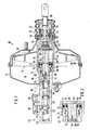
- the brake booster master cylinder assembly shown has a brake booster 10 with a two-part booster housing 12 which is provided for mounting on the bulkhead of a motor vehicle and has an interior space which is divided into two housing chambers 16 and 18 by a movable wall 14.
- the brake booster 10 also includes a control valve 20 with a tubular valve housing 22 on which an outer annular valve seat 24 is formed in one piece. This is also associated with an annular valve body 26, which is axially adjustable with respect to the valve housing 22, but is sealed with respect to the valve housing and also cooperates with an inner valve seat 28 which is formed on a rod-shaped actuating member 30.
- the actuator 30 can be pivotally connected to a brake pedal and is biased into its rest position, to the right in FIG. 1, by a spring 32 supported on the valve housing 22. Another spring 34 supported on the actuator 30 presses the valve body 26 in the direction of the two valve seats 24 and 28.
- valve body 26 In the rest position shown, the valve body 26 is held against the inner valve seat 28, while it assumes a position in which it prevents the valve body 26 from also abutting the outer valve seat 24. As a result, a connection between the two housing chambers 16 and 18 controlled by the outer valve seat 24 is open, while a connection between the atmosphere and the housing chamber 16 controlled by the inner valve seat 28 is closed.
- the housing chamber 18 is connected to a vacuum source, for example the suction line of an internal combustion engine; the negative pressure generated there prevails in the illustrated rest position of the control valve 20 in both housing chambers 16 and 18.
- Components of the movable wall 14 are a support part 36, which is formed in one piece with the valve housing 22, and a membrane 38, which connects the support part 36 tightly to the booster housing 12.
- the brake booster 10 is of a conventional type.
- the movable wall 14 has, as a further component, a ballast piston 40 which is formed in one piece with the support part 36 and the valve housing 22 and delimits a ballast chamber 42 to the rear, to the right in FIG. 1.
- the ballast chamber 42 is delimited radially outwards by a sleeve-shaped boundary 44, which is likewise formed in one piece with the support part 36.
- An elastomer body 46 is embedded in a central recess of the upstream piston 40, on which a small front end face of the actuating member 30 is visible from the rear and a size from the front re rear end face of a push rod 48 bears in such a way that the elastomer body 46 is completely enclosed and acts in a manner known per se as a force booster.
- a master cylinder 50 for a dual-circuit brake system is assigned to the brake booster 10.
- the master cylinder 50 has a cylinder housing 52 which is arranged coaxially with the booster housing 12 and is attached to the front side thereof. A considerable part, about a third of the total length of the master cylinder 50 in the example shown, is accommodated within the brake booster 10.
- a primary pressure piston 54 delimits a primary pressure chamber 56, to which a first brake circuit can be connected;
- a secondary pressure piston 58 delimits a secondary pressure chamber 60, to which a second brake circuit can be connected.
- Both pressure pistons 54 and 58 have the same diameter, which is considerably smaller than the inner diameter of the sleeve-shaped boundary 44 of the ballast chamber 42.
- the primary pressure piston 54 and the push rod 58 consist of one piece; an axial bore 62 extends through both. This is penetrated by a central diametrical channel 64 and a rear diametrical channel 66 and a front diametrical channel 68 and is continuously connected to the ballast chamber 42 via the rear diametrical channel 66, which is formed by a slotted spring sleeve.
- annular intermediate piston 70 is arranged, which against the cylindrical inner wall of the sleeve-shaped boundary 44 with a first seal 72 of larger diameter, against an enlarged inner wall section of the cylinder housing 52 with a second seal 74 of medium diameter and against one seals the cylindrical outer surface of the push rod 48 with a third seal 76 of smaller diameter.
- a spring 78 - Between a rear end face of the cylinder housing 52 and the Intermediate piston 70 is a spring 78 - a disc spring is shown - which tends to press the intermediate piston 70 away from the cylinder housing 52 in the direction of the pilot piston 40.
- the space containing the spring 78 is permanently connected to the housing chamber 18 of the brake booster 10; Therefore, there is also negative pressure in this room when the brake booster is ready for operation.
- the effective diameter of the first seal 72 is so much larger than that of the second seal 74 that, when the brake booster 10 is ready for operation, brake fluid, which fills the ballast chamber 42 and is under atmospheric pressure, the intermediate piston 70 according to FIG. 2 against the rear end face of the cylinder housing 52 presses.
- the third seal 76 is at a relatively large axial distance in front of the central diametrical channel 64, so that this opens into the ballast chamber 42.
- the spring 78 ensures that the third seal 76 , as shown in FIG. 1, stands over the central diametrical channel 64 or immediately in front of it.
- the middle diametrical channel 64 forms, together with the third seal 76, a relief valve 80 which, after failure of the negative pressure in the front housing chamber 18 when the brake is actuated, allows a very slight forward movement of the push rod 48 to pass around the middle diametrical channel 64 with a to connect on the inside of the intermediate piston 70 in front of the third seal 76, axially parallel channel 82, which is continuously connected via a bore 84 in the cylinder housing 52 to a primary connection 86 for a pressure medium reservoir, not shown.
- the bore 84 is also through a radial bore 88 in the cylinder housing 52 connected to the primary pressure chamber 56 as long as the primary pressure piston 54 assumes its rest position shown in FIG. 1.
- the cylinder housing 52 also has a secondary connection 90 for the pressure medium reservoir; this connection is connected by a radial bore 92 to the secondary pressure chamber 60, as long as the secondary pressure piston 58 assumes its rest position shown.
- a check valve 94 is arranged at the front end of the axial bore 62, which allows a pressure medium flow as long as the pressure in the primary pressure chamber 56 is lower than in the upstream chamber 42.
- An additional relief valve 96 which is also designed as a check valve, is assigned to the front diametrical channel 68 and allows brake fluid to flow out of the upstream chamber 42 via the bore 84 into the pressure medium reservoir if the pressure in the upstream chamber 42 exceeds a certain amount, regardless of whether the brake booster 10 is intact or not.
- the valve body 26 lies against the outer valve seat 24 and thereby interrupts the connection between the two housing chambers 16 and 18, in which until then there was the same negative pressure.
- the inner valve seat 28 is lifted from the valve body 26 by further forward movement of the actuating member 30, as a result of which air can flow in from the rear through the valve housing 22 into the rear housing chamber 16, while the negative pressure in the front housing chamber 18 is maintained. Due to this pressure difference, the movable wall 14 becomes moved forward so that the pre-piston 40 pushes the push rod 48 together with the primary pressure piston 54 forward. As a result, the brake fluid in the ballast chamber 42 is pressurized.
- the intermediate piston 70 cannot evade this pressure since, according to FIG. 2, it assumes its front end position from the outset with the brake booster 10 intact.
Landscapes
- Engineering & Computer Science (AREA)
- Transportation (AREA)
- Mechanical Engineering (AREA)
- Braking Systems And Boosters (AREA)
- Transmission Of Braking Force In Braking Systems (AREA)
Abstract
In einem Verstärkergehäuse (12) trennt eine bewegliche Wand (14) zwei Gehäusekammern (16, 18) voneinander. Ein Steuerventil (20) verbindet in einer Ruhestellung die beiden Gehäusekammern (16, 18) miteinander, trennt sie jedoch in einer Betätigungsstellung voneinander und verbindet eine (16) von ihnen mit einer Quelle eines Druckes, der sich vom Druck in der anderen Kammer (18) unterscheidet. Ein Zylindergehäuse (52) ist an das Verstärkergehäuse (12) angebaut, ragt in dieses hinein und enthält mindestens einen Druckkolben (54), der einen Druckraum (56) zum Unterdrucksetzen eines Bremskreises begrenzt. Gemeinsam mit der beweglichen Wand (14) ist ein Vorschaltkolben (40) bewegbar, der eine größere wirksame Fläche als der Druckkolben (54) hat und eine Vorschaltkammer (42) begrenzt. Die Vorschaltkammer (42) ist bei Ausfall des Bremskraftverstärker (10) durch ein Entlastungsventil (80) von Druck entlastbar. Dabei sind Vorschaltkolben (40) und Vorschaltkammer (42) innerhalb des Verstärkergehäuses (12) angeordnet, und der Vorschaltkolben (40) ist Bestandteil der beweglichen Wand (14). Dadurch läßt sich die Baugruppe bei gegebenen Anforderungen an ihre Leistungsfähigkeit besonders raumsparend und leicht gestalten.A movable wall (14) separates two housing chambers (16, 18) from one another in an amplifier housing (12). A control valve (20) connects the two housing chambers (16, 18) to one another in a rest position, but separates them from one another in an actuation position and connects one (16) of them to a source of a pressure which is different from the pressure in the other chamber (18 ) differs. A cylinder housing (52) is attached to the booster housing (12), projects into it and contains at least one pressure piston (54) which delimits a pressure chamber (56) for pressurizing a brake circuit. A series piston (40) can be moved together with the movable wall (14) and has a larger effective area than the pressure piston (54) and delimits a series chamber (42). If the brake booster (10) fails, the upstream chamber (42) can be relieved of pressure by means of a relief valve (80). The series piston (40) and the series chamber (42) are arranged inside the booster housing (12), and the series piston (40) is part of the movable wall (14). As a result, the assembly can be designed to be particularly space-saving and light for given performance requirements.
Description
Die Erfindung betrifft eine Bremskraftverstärker-Hauptzylinderbaugruppe mit
- einem Verstärkergehäuse, in dem eine bewegliche Wand zwei Gehäusekammern voneinander trennt,
- einem Steuerventil, das in einer Ruhestellung die beiden Gehäusekammern miteinander verbindet, in einer Betätigungsstellung jedoch die beiden Gehäusekammern voneinander trennt und eine von ihnen mit einer Quelle eines Druckes verbindet, der sich vom Druck in der anderen Kammer unterscheidet,
- einem Zylindergehäuse, das an das Verstärkergehäuse angebaut ist, in dieses hineinragt und mindestens einen Druckkolben enthält, der einen Druckraum zum Unterdrucksetzen eines Bremskreises begrenzt,
- einem Vorschaltkolben, der eine größere wirksame Fläche als der Druckkolben hat, eine Vorschaltkammer begrenzt und gemeinsam mit der beweglichen Wand bewegbar ist, und
- einem Entlastungsventil, durch das die Vorschaltkammer bei Ausfall des Bremskraftverstärkers von Druck entlastbar ist.The invention relates to a brake booster master cylinder assembly
an amplifier housing in which a movable wall separates two housing chambers from one another,
a control valve which connects the two housing chambers to one another in a rest position, but separates the two housing chambers from one another in an actuating position and connects one of them to a source of a pressure which differs from the pressure in the other chamber,
a cylinder housing which is attached to the booster housing, projects into it and contains at least one pressure piston which delimits a pressure chamber for pressurizing a brake circuit,
a ballast piston which has a larger effective area than the pressure piston, delimits a ballast chamber and is movable together with the movable wall, and
- A relief valve through which the ballast can be relieved of pressure in the event of failure of the brake booster.
Bei einer bekannten Baugruppe dieser Gattung (DE-A-2 460 529) ist das Zylindergehäuse mit einem Flansch, der an einem seiner beiden Enden ausgebildet ist, am Verstärkergehäuse befestigt und weist einen kurzen Endabschnitt auf, der im Verstärkergehäuse zentriert ist. Im Zylindergehäuse sind axial hintereinander ein Primärdruckraum und ein Sekundärdruckraum ausgebildet, die durch je einen Druckkolben begrenzt sind und an die je ein Bremskreis eines Kraftfahrzeugs anschließbar ist. Zwischen dem Primärdruckraum und dem am Verstärkergehäuse befestigten Ende des Zylindergehäuses ist eine Vorschaltkammer ausgebildet, deren Durchmesser größer ist als derjenige des Primärdruckraumes. Die Vorschaltkammer enthält einen Vorschaltkolben, der mit der beweglichen Wand im Verstärkergehäuse durch eine Schubstange verbunden ist. Die Vorschaltkammer ist mit einem Anschluß für ein Druckmittelreservoir durch ein Entlastungsventil verbunden, das normalerweise durch einen Unterdruck geschlossen gehalten wird, der bei betriebsbereitem Bremskraftverstärker im Verstärkergehäuse herrscht. Bei Betätigung der Bremse verschiebt die Druckstange den Vorschaltkolben, so daß dieser in der Vorschaltkammer Bremsflüssigkeit verdrängt, die ihrerseits den primärseitigen Druckkolben vorschiebt. Die Strecke, um die sich dieser Druckkolben vorwärts bewegt, ist im Verhältnis der wirksamen Flächen des Vorschaltkolbens und dieses Druckkolbens größer als der Weg des Vorschaltkolbens. Bei intaktem Bremskraftverstärker und somit geschlossenem Entlastungsventil besteht also eine Wegübersetzung zwischen Vorschaltkolben und primärseitigem Druckkolben. Der sekundärseitige Druckkolben hat eine gleich große wirksame Fläche wie der primärseitige Druckkolben und bewegt sich deshalb um eine ebenso große Strecke wie dieser. Bei Ausfall des Bremskraftverstärkers öffnet sich das Entlastungsventil, so daß die bei Betätigung der Bremse vom Vorschaltkolben verdrängte Bremsflüssigkeit in das Druckmittelreservoir abströmt, ohne daß sich der Druck in der Vorschaltkammer erhöht. Der Vorschaltkolben verschiebt über eine an ihm ausgebildete axiale Verlängerung den primärseitigen Druckkolben unmittelbar, so daß dieser sich nur um die gleiche Strecke bewegt wie der Vorschaltkolben. Bei ausgefallenem Bremskraftverstärker wird die Betätigungskraft, die für die gemeinsame Verschiebung von Vorschaltkolben und primärseitigem Druckkolben aufgebracht werden muß, also nicht mehr von der wirksamen Fläche des Vorschaltkolbens bestimmt sondern von der kleineren Fläche des primärseitigen Druckkolbens.In a known assembly of this type (DE-A-2 460 529) the cylinder housing is fixed to the booster housing with a flange which is formed at one of its two ends and has a short end section which is centered in the booster housing. A primary pressure chamber and a secondary pressure chamber are formed axially one behind the other in the cylinder housing and are each delimited by a pressure piston and to which a brake circuit of a motor vehicle can be connected. Between the primary pressure chamber and the end of the cylinder housing fastened to the booster housing, a ballast chamber is formed, the diameter of which is larger than that of the primary pressure chamber. The ballast chamber contains a ballast piston which is connected to the movable wall in the amplifier housing by a push rod. The ballast chamber is connected to a connection for a pressure medium reservoir by a relief valve which is normally kept closed by a negative pressure which prevails in the booster housing when the brake booster is ready for operation. When the brake is actuated, the push rod displaces the ballast piston so that it displaces brake fluid in the ballast chamber, which in turn pushes the pressure piston on the primary side. The distance by which this pressure piston moves forward is greater in relation to the effective areas of the series piston and this pressure piston than the path of the series piston. If the brake booster is intact and the relief valve is closed, there is therefore a path translation between the upstream piston and the pressure piston on the primary side. The secondary-side pressure piston has the same effective area as the primary-side pressure piston and therefore moves for an equally large distance as this. If the brake booster fails, the relief valve opens, so that the brake fluid displaced by the upstream piston when the brake is actuated flows into the pressure medium reservoir without the pressure in the upstream chamber increasing. The series piston moves the primary-side pressure piston directly via an axial extension formed on it, so that it moves only the same distance as the series piston. If the brake booster fails, the actuating force that must be applied for the joint displacement of the pilot piston and the primary-side pressure piston is no longer determined by the effective area of the pilot piston but by the smaller area of the primary-side pressure piston.
Eine andere bekannte Hauptzylinderbaugruppe (US-A-4 086 770) weist ein Zylindergehäuse auf, das ebenfalls zum Anbauen an einen Bremskraftverstärker geeignet ist und zwei Druckkolben in Tandemanordnung sowie einen dem primärseitigen Druckkolben vorgeschalteten Vorschaltkolben aufweist. Der Vorschaltkolben hat auch hier eine größere wirksame Fläche als der primärseitige Druckkolben, besteht aber mit diesem aus einem Stück, so daß beide sich nur gemeinsam bewegen können. Bei Betätigung der Bremse verdrängt der Vorschaltkolben ein größeres Volumen als der Druckkolben freigibt. Infolgedessen strömt Bremsflüssigkeit aus der Vorschaltkammer an einer Lippendichtung des primärseitigen Druckkolbens vorbei in den zugehörigen Druckraum, so daß der an diesen angeschlossene Bremskreis schnell gefüllt wird. Wenn der Druck im primärseitigen Druckraum einen bestimmten Betrag überschreitet, öffnet ein Entlastungsventil, das eine Verbindung zwischen der Vorschaltkammer und einem Druckmittelreservoir freigibt, so daß die Vorschaltkammer von Druck entlastet wird und die zum weiteren Betätigen der Bremse erforderliche Kraft nur noch von der wirksamen Fläche des primärseitigen Druckkolbens bestimmt wird.Another known master cylinder assembly (US-A-4 086 770) has a cylinder housing which is also suitable for mounting on a brake booster and has two pressure pistons in tandem arrangement and a series piston upstream of the primary pressure piston. The primary piston also has a larger effective area than the primary-side pressure piston, but consists of one piece with it, so that both can only move together. When the brake is actuated, the series piston displaces a larger volume than the pressure piston releases. As a result, brake fluid flows from the ballast chamber past a lip seal of the primary-side pressure piston into the associated pressure chamber, so that the brake circuit connected to it is quickly filled. If the pressure in the primary-side pressure chamber exceeds a certain amount, a relief valve opens, which releases a connection between the ballast chamber and a pressure medium reservoir, so that the ballast chamber is relieved of pressure and the force required for further actuation of the brake only from the effective area of the primary-side pressure piston is determined.
Beide beschriebenen bekannten Baugruppen haben, vom hinteren Ende des Verstärkergehäuses bis zum vorderen Ende des Zylindergehäuses gemessen, eine große Baulänge. Massenträgheitskräfte, die infolge von Erschütterungen auf das Zylindergehäuse samt darin untergebrachten Bauteilen und angebautem Druckmittelreservoir einwirken, können große Biegemomente im Bereich der Verbindung zwischen Zylindergehäuse und Verstärkergehäuse hervorrufen, so daß das gesamte Verstärkergehäuse, das üblicherweise die einzige Verbindung zwischen dem Zylindergehäuse und einem tragenden Teil des zugehörigen Fahrzeugs darstellt, kräftig gestaltet werden muß.Both known assemblies described have a large overall length, measured from the rear end of the booster housing to the front end of the cylinder housing. Mass inertia forces, which act on the cylinder housing together with the components housed therein and the pressure medium reservoir installed as a result of vibrations, can cause large bending moments in the area of the connection between the cylinder housing and the booster housing, so that the entire booster housing, which is usually the only connection between the cylinder housing and a supporting part of the represents associated vehicle, must be designed strong.
Der Erfindung liegt deshalb die Aufgabe zugrunde, eine Bremskraftverstärker-Hauptzylinderbaugruppe bei gegebenen Anforderungen an ihre Leistungsfähigkeit raumsparender und leichter zu gestalten.The invention is therefore based on the object of making a brake booster master cylinder assembly more space-saving and lighter for given performance requirements.
Die Aufgabe ist bei einer Bremskraftverstärker-Hauptrylinderbaugruppe der eingangs beschriebenen Gattung erfindungsgemäß dadurch gelöst, daß
- Vorschaltkolben und Vorschaltkammer innerhalb des Verstärkergehäuses angeordnet sind und
- der Vorschaltkolben Bestandteil der beweglichen Wand ist.The object is achieved according to the invention in a brake booster master cylinder assembly of the type described at the outset in that
- Ballast piston and ballast chamber are arranged within the amplifier housing and
- The pilot piston is part of the movable wall.
Diese erfindungsgemäße Lösung ist unabhängig davon vorteilhaft, ob der Vorschaltkolben, insoweit übereinstimmend mit der DE-A-2 460 529 zum Herstellen einer Wegübersetzung dient oder gemäß der US-PS 4 086 770 als Schnellfüllkolben vorgesehen ist.This solution according to the invention is advantageous regardless of whether the upstream piston, in so far as it is in accordance with DE-A-2 460 529, is used to produce a travel ratio or is provided as a quick-filling piston according to US Pat. No. 4,086,770.
Das Merkmal, daß Vorschaltkolben und Vorschaltkammer innerhalb des Verstärkergehäuses angeordnet sind, ist schon gemäß den nicht vorveröffentlichten europäischen Patentanmeldungen 86 103 000.5 und 86 103 001.3 der Anmelderin vorgesehen; dort ist der Vorschaltkolben jedoch jeweils ein von der beweglichen Wand getrenntes Bauteil.The feature that the pilot piston and the pilot chamber are arranged within the booster housing is already provided in accordance with the not previously published
Die Erfindung ist vorzugsweise dadurch weitergebildet, daß der Vorschaltkolben einstückig mit einem Stützteil der beweglichen Wand ausgebildet ist, welches mit dem Verstärkergehäuse durch eine Membran verbunden ist. Auf diese Weise wird die Zahl der Einzelteile der erfindungsgemäßen Baugruppe vermindert und deren Herstellung entsprechend vereinfacht.The invention is preferably further developed in that the ballast piston is formed in one piece with a support part of the movable wall, which is connected to the booster housing by a membrane. In this way, the number of individual parts of the assembly according to the invention is reduced and its manufacture is correspondingly simplified.
Aus den gleichen Gründen ist es vorteilhaft, wenn der Vorschaltkolben einstückig mit einer hülsenförmigen äußeren Umgrenzung der Vorschaltkammer ausgebildet ist.For the same reasons, it is advantageous if the ballast piston is formed in one piece with a sleeve-shaped outer boundary of the ballast chamber.
Dabei ist es vorteilhaft, wenn die hülsenförmige Umgrenzung mittels einer ersten Dichtung einen Zwischenkolben umschließt, der zusätzlich mittels einer zweiten Dichtung vom Zylindergehäuse umschlossen ist.It is advantageous if the sleeve-shaped boundary encloses an intermediate piston by means of a first seal, which is additionally enclosed by the cylinder housing by means of a second seal.
Diese Ausführungsform ist vorzugsweise dadurch weitergebildet, daß
- der Zwischenkolben am Zylindergehäuse über eine Feder abgestützt ist, die bestrebt ist, ihn in Richtung zum Vorschaltkolben zu drücken,
- ein vom Zwischenkolben begrenzter Raum zwischen der ersten und der zweiten Dichtung an eine der Gehäusekammern angeschlossen ist, die bei intaktem Bremskraftverstärker unter geringerem Druck steht als die andere Gehäusekammer, wodurch die Feder überwunden wird, und
- der Zwischenkolben das Entlastungsventil derart steuert, daß es sich im Verlauf einer Bremsbetätigung bei ausgefallenem Bremskraftverstärker früher öffnet als bei intaktem Bremskraftverstärker.This embodiment is preferably developed in that
the intermediate piston is supported on the cylinder housing by a spring which tends to push it towards the pilot piston,
- A space delimited by the intermediate piston between the first and the second seal is connected to one of the housing chambers which, when the brake booster is intact, is under less pressure than the other housing chamber, as a result of which the spring is overcome, and
- The intermediate piston controls the relief valve in such a way that it opens earlier in the course of a brake application when the brake booster fails than when the brake booster is intact.
Diese Ausführungsform kann dadurch weiter ausgestaltet sein, daß der Zwischenkolben mittels einer dritten Dichtung den Druckkolben umschließt und das Entlastungsventil von dieser dritten Dichtung in Verbindung mit einem am Druckkolben ausgebildeten Kanal gebildet ist.This embodiment can be further developed in that the intermediate piston encloses the pressure piston by means of a third seal and the relief valve is formed by this third seal in connection with a channel formed on the pressure piston.
Gemäß einem weiteren Merkmal der Erfindung ist die Vorschaltkammer mit dem Druckraum durch ein Rückschlagventil zum schnellen Füllen des zugehörigen Bremskreises verbunden.According to a further feature of the invention, the ballast chamber is connected to the pressure chamber by a check valve for quickly filling the associated brake circuit.
Es ist ferner vorteilhaft, wenn die Vorschaltkammer mit einem Anschluß für ein Druckmittelreservoir durch ein zusätzliches, vom Zustand des Bremskraftverstärkers unabhängiges Entlastungsventil verbunden ist. Dieses Ventil begrenzt den Druck, der in der Vorschaltkammer höchstens entstehen kann, und verhindert somit, daß durch übermäßigen Druckaufbau in der Vorschaltkammer die Betätigung der Bremse unnötig erschwert wird.It is also advantageous if the ballast chamber is connected to a connection for a pressure medium reservoir by an additional relief valve which is independent of the state of the brake booster. This valve limits the pressure that can arise in the ballast at most, and thus prevents the brake from being unnecessarily difficult due to excessive pressure build-up in the ballast chamber.
Ferner kann der Vorschaltkolben einen Elastomerkörper als Kraftübersetzer zwischen einem Betätigungsglied und dem Druck kolben enthalten. Solche Elastomerkörper sind bei Bremskraftverstärkern üblich; neu ist jedoch ihrer raumsparende Anordnung im Vorschaltkolben.Furthermore, the ballast piston can have an elastomer body as a force converter between an actuator and the pressure piston included. Such elastomer bodies are common in brake boosters; What is new, however, is their space-saving arrangement in the pilot piston.
Die Anzahl der Bauteile der erfindungsgemäßen Baugruppe läßt sich weiter dadurch vermindern, daß der Vorschaltkolben mit einem Ventilsitz und einem Ventilgehäuse des Steuerventils einstückig ausgebildet ist.The number of components of the assembly according to the invention can be further reduced in that the ballast piston is formed in one piece with a valve seat and a valve housing of the control valve.
Ein Ausführungsbeispiel der Erfindung wird im Folgenden anhand schematischer Zeichnungen mit weiteren Einzelheiten beschrieben. Es zeigt:
- Fig. 1 einen Axialschnitt durch eine BremskraftverstärkerHauptzylinderbaugruppe in unbetätigtem Zustand und bei nicht betriebsbereitem Bremskraftverstärker;
- Fig. 2 einen etwas vergrößerten Ausschnitt aus Fig. 1 ebenfalls in unbetätigtem Zustand, jedoch bei betriebsbereitem Bremskraftverstärker.
- 1 shows an axial section through a brake booster master cylinder assembly in the unactuated state and when the brake booster is not ready for operation;
- Fig. 2 is a somewhat enlarged section of Fig. 1 also in the unactuated state, but with the brake booster ready for operation.
Die dargestellte Bremskraftverstärker-Hauptzylinderbaugruppe hat einen Bremskraftverstärker 10 mit einem zweiteiligen Verstärkergehäuse 12, das zum Anbauen an die Spritzwand eines Kraftfahrzeugs vorgesehen ist und einen Innenraum hat, der durch eine bewegliche Wand 14 in zwei Gehäusekammern 16 und 18 unterteilt ist.The brake booster master cylinder assembly shown has a brake booster 10 with a two-
Zum Bremskraftverstärker 10 gehört ferner ein Steuerventil 20 mit einem rohrförmigen Ventilgehäuse 22, an dem ein äußerer ringförmiger Ventilsitz 24 einstückig ausgebildet ist. Diesem ist ein ebenfalls ringförmiger Ventilkörper 26 zugeordnet, der in Bezug auf das Ventilgehäuse 22 axial verstellbar, gegenüber dem Ventilgehäuse jedoch abgedichtet ist und ferner mit einem inneren Ventilsitz 28 zusammenwirkt, der an einem stangenförmigen Betätigungsglied 30 ausgebildet ist. Das Betätigungsglied 30 läßt sich gelenkig mit einem Bremspedal verbinden und ist durch eine am Ventilgehäuse 22 abgestützte Feder 32 in seine Ruhestellung, in Fig. 1 nach rechts, vorgespannt. Eine weitere, am Betätigungsglied 30 abgestützte Feder 34 drückt den Ventilkörper 26 in Richtung auf die beiden Ventilsitze 24 und 28 hin.The brake booster 10 also includes a
In der abgebildeten Ruhestellung ist der Ventilkörper 26 am inneren Ventilsitz 28 anliegend gehalten, während dieser eine Stellung einnimmt, in der er den Ventilkörper 26 daran hindert, auch am äußeren Ventilsitz 24 anzuliegen. Infolgedessen ist eine vom äußeren Ventilsitz 24 gesteuerte Verbindung zwischen den beiden Gehäusekammern 16 und 18 offen während eine vom inneren Ventilsitz 28 gesteuerte Verbindung zwischen der Atmosphäre und der Gehäusekammer 16 geschlossen ist. Die Gehäusekammer 18 ist an eine Unterdruckquelle, beispielsweise die Saugleitung eines Verbrennungsmotors, angeschlossen; der dort erzeugte Unterdruck herrscht bei der abgebildeten Ruhestellung des Steuerventils 20 in beiden Gehäusekammern 16 und 18.In the rest position shown, the
Bestandteile der beweglichen Wand 14 sind ein Stützteil 36, das mit dem Ventilgehäuse 22 einstückig ausgebildet ist, sowie eine Membran 38, die das Stützteil 36 dicht mit dem Verstärkergehäuse 12 verbindet. Insoweit ist der Bremskraftverstärker 10 von üblicher Bauart.Components of the
Erfindungsgemäß weist die bewegliche Wand 14 als weiteren Bestandteil einen Vorschaltkolben 40 auf, der mit dem Stützteil 36 und dem Ventilgehäuse 22 einstückig ausgebildet ist und eine Vorschaltkammer 42 nach hinten, in Fig. 1 nach rechts, begrenzt. Radial nach außen ist die Vorschaltkammer 42 durch eine hülsenförmige Umgrenzung 44 begrenzt, die ebenfalls einstückig mit dem Stützteil 36 ausgebildet ist. In eine zentrale Aussparung des Vorschaltkolbens 40 ist ein Elastomerkörper 46 eingebettet, an dem von hinten her eine kleine vordere Stirnfläche des Betätigungsgliedes 30 und von vorne her eine größe re hintere Stirnfläche einer Schubstange 48 derart anliegt, daß der Elastomerkörper 46 vollständig umschlossen ist und in an sich bekannter Weise als Kraftübersetzer wirkt.According to the invention, the
Dem Bremskraftverstärker 10 ist ein Hauptzylinder 50 für eine Zweikreis-Bremsanlage zugeordnet. Der Hauptzylinder 50 hat ein Zylindergehäuse 52, das gleichachsig mit dem Verstärkergehäuse 12 angeordnet und an dessen Vorderseite befestigt ist. Ein erheblicher Teil, im dargestellten Beispiel etwa ein Drittel der Gesamtlänge des Hauptzylinders 50 ist innerhalb des Bremskraftverstärkers 10 untergebracht. In dem Zylindergehäuse 52 begrenzt ein primärer Druckkolben 54 einen primären Druckraum 56, an den ein erster Bremskreis anschließbar ist; ein sekundärer Druckkolben 58 begrenzt einen sekundären Druckraum 60, an den ein zweiter Bremskreis anschließbar ist.A
Beide Druckkolben 54 und 58 haben den gleichen Durchmesser, der erheblich kleiner ist als der Innendurchmesser der hülsenförmigen Umgrenzung 44 der Vorschaltkammer 42. Der primäre Druckkolben 54 besteht mit der Schubstange 58 aus einem Stück; durch beide erstreckt sich eine axiale Bohrung 62 hindurch. Diese wird von einem mittleren diametralen Kanal 64 sowie einem hinteren diametralen Kanal 66 und einem vorderen diametralen Kanal 68 durchsetzt und ist über den hinteren diametralen Kanal 66, der von einer geschlitzten Federhülse gebildet ist, ständig mit der Vorschaltkammer 42 verbunden.Both
Zwischen dem Vorschaltkolben 40 und dem primären Druckkolben 54 ist ein ringförmiger Zwischenkolben 70 angeordnet, der gegen die zylindrische Innenwand der hülsenförmigen Umgrenzung 44 mit einer ersten Dichtung 72 größeren Durchmessers, gegen einen erweiterten Innenwandabschnitt des Zylindergehäuses 52 mit einer zweiten Dichtung 74 mittleren Durchmessers und gegen eine zylindrische Außenfläche der Schubstange 48 mit einer dritten Dichtung 76 kleineren Durchmessers abdichtet. Zwischen einer hinteren Stirnfläche des Zylindergehäuses 52 und dem Zwischenkolben 70 ist eine Feder 78 - dargestellt ist eine Tellerfeder - angeordnet, die bestrebt ist, den Zwischenkolben 70 vom Zylindergehäuse 52 weg, in Richtung zum Vorschaltkolben 40 hin, zu drücken.Between the
Der Raum, der die Feder 78 enthält, ist mit der Gehäusekammer 18 des Bremskraftverstärkers 10 ständig verbunden; in diesem Raum herrscht deshalb bei betriebsbereitem Bremskraftverstärker ebenfalls Unterdruck. Der wirksame Durchmesser der ersten Dichtung 72 ist um so viel größer als derjenige der zweiten Dichtung 74, daß bei betriebsbereitem Bremskraftverstärker 10 Bremsflüssigkeit, welche die Vorschaltkammer 42 füllt und unter Atmosphärendruck steht, den Zwischenkolben 70 gemäß Fig. 2 gegen die hintere Stirnfläche des Zylindergehäuses 52 drückt. Dabei steht die dritte Dichtung 76 in verhältnismäßig großem axialen Abstand vor dem mittleren diametralen Kanal 64, so daß dieser in die Vorschaltkammer 42 mündet. Falls jedoch, beispielsweise in Folge eine Undichtheit des Verstärkergehäuses 12 oder der Membran 38, oder bei Stillstand des Verbrennungsmotors, an den die Gehäusekammer 18 angeschlossen ist, in dieser Atmosphärendruck oder ein ungenugendes Vakuum herrscht, sorgt die Feder 78 dafür, daß die dritte Dichtung 76, wie in Fig. 1 dargestellt, über dem mittleren diametralen Kanal 64 oder unmittelbar davor steht.The space containing the
Der mittlere diametrale Kanal 64 bildet zusammen mit der dritten Dichtung 76 ein Entlastungsventil 80, das nach Ausfall des Unterdruckes in der vorderen Gehäusekammer 18 bei Betätigung der Bremse eine sehr geringe Bewegung der Schubstange 48 nach vorne genügen läßt, um den mittleren diametralen Kanal 64 mit einem an der Innenseite des Zwischenkolbens 70 vor der dritten Dichtung 76 ausgebildeten achsparallelen Kanal 82 zu verbinden, der über eine Bohrung 84 im Zylindergehäuse 52 ständig mit einem primären Anschluß 86 für ein nicht dargestelltes Druckmittelreservoir verbunden ist. Die Bohrung 84 ist zusätzlich durch eine radiale Bohrung 88 im Zylindergehäuse 52 mit dem primären Druckraum 56 verbunden, solange der primäre Druckkolben 54 seine in Fig. 1 abgebildete Ruhestellung einnimmt.The middle
Das Zylindergehäuse 52 weist ferner einen sekundären Anschluß 90 für das Druckmittelreservoir auf; dieser Anschluß ist durch eine radiale Bohrung 92 mit dem sekundären Druckraum 60 verbunden, solange der sekundäre Druckkolben 58 seine abgebildete Ruhestellung einnimmt.The
Im primären Druckkolben 54 ist am vorderen Ende der axialen Bohrung 62 ein Rückschlagventil 94 angeordnet, das eine Druckmittelströmung so lange zuläßt, wie der Druck im primären Druckraum 56 kleiner ist als in der Vorschaltkammer 42.In the
Dem vorderen diametralen Kanal 68 ist ein ebenfalls als Rückschlagventil ausgebildetes zusätzliches Entlastungsventil 96 zugeordnet, das Bremsflüssigkeit von der Vorschaltkammer 42 über die Bohrung 84 in das Druckmittelreservoir abströmen läßt, wenn der Druck in der Vorschaltkammer 42 einen bestimmten Betrag überschreitet, unabhängig davon, ob der Bremskraftverstärker 10 intakt ist oder nicht.An
Wenn die dargstellte Bremskraftverstärker-Hauptzylinderbaugruppe bei intaktem Bremskraftverstärker 10 betätigt wird, indem das Betätigungsglied 30 vom zugehörigen Bremspedal nach vorne verschoben wird, legt sich der Ventilkörper 26 gegen den äußeren Ventilsitz 24 und unterbricht dadurch die Verbindung zwischen den beiden Gehäusekammern 16 und 18, in denen bis dahin der gleiche Unterdruck geherrscht hat. Unmittelbar darauf wird durch weitere Vorwärtsbewegung des Betätigungsgliedes 30 der innere Ventilsitz 28 vom Ventilkörper 26 abgehoben, wodurch Luft von hinten her durch das Ventilgehäuse 22 in die hintere Gehäusekammer 16 einströmen kann, während der Unterdruck in der vorderen Gehäusekammer 18 erhalten bleibt. Durch diesen Druckunterschied wird die bewegliche Wand 14 nach vorne verschoben, so daß der Vorschaltkolben 40 die Schubstange 48 samt primärem Druckkolben 54 vorwärts schiebt. Dadurch wird die Bremsflüssigkeit in der Vorschaltkammer 42 unter Druck gesetzt. Diesem Druck kann der Zwischenkolben 70 nicht ausweichen, da er gemäß Fig. 2 bei intaktem Bremskraftverstärker 10 von vorneherein seine vordere Endstellung einnimmt.If the illustrated brake booster master cylinder assembly is actuated with the brake booster 10 intact by moving the actuating
Folglich strömt in kurzer Zeit eine große Menge Bremsflüssigkeit aus der Vorschaltkammer 42 durch das Rückschlagventil 94 in den primären Druckraum 56, so daß der daran angeschlossene Bremskreis rasch gefüllt und dabei auch der sekundäre Druckkolben 58 vorgeschoben wird, so daß der an den sekundären Druckraum 60 angeschlossene Bremskreis ebenfalls rasch gefüllt wird. Der ansteigende Druck in der Vorschaltkammer 42 läßt das als Rückschlagventil ausgebildete Entlastungsventil 96 öffnen; infolgedessen nimmt das Druckmittelreservoir überschüssiges Druckmittel aus der Vorschaltkammer 42 auf, wodurch verhindert wird, daß in dieser ein den Kraftaufwand unnötig erhöhender Überdruck entsteht. Unmittelbar darauf bewirkt das Druckgefälle zwischen dem primären Druckraum 56 und der Vorschaltkammer 42, daß das Rückschlagventil 94 schließt.As a result, a large amount of brake fluid flows from the
Wenn jedoch die Bremse betätigt wird, während der Bremskraftverstärker 10 ausgefallen ist und der Zwischenkolben 70 infolgedessen seine Stellung gemäß Fig. 1 einnimmt, genügt eine nun vom Betätigungsglied 30 ohne Unterstützung durch den Bremskraftverstärker 10 hervorgerufene, für den Fahrer noch nicht oder kaum bemerkbare Vorwärtsbewegung der Schubstange 48, um das Entlastungsventil 80 zu öffnen, so daß Bremsflüssigkeit aus der Vorschaltkammer 42 über den hinteren diametralen Kanal 66, die axiale Bohrung 62, den mittleren diametralen Kanal 64, den achsparallelen Kanal 82, die Bohrung 84 und den Anschluß 86 in das Druckmittelreservoir abströmt. Eine nennenswerte Druckerhöhung in der Vorschaltkammer 42 findet somit nicht statt; der Fahrer hat infolgedessen nur die Kraft aufzubrin gen, die sich aus der wirksamen Fläche des primären Druckkolbens 54 und dem allmählich ansteigenden Druck in den beiden Bremskreisen ergibt. Der zum Füllen der Bremskreise erforderliche Pedalweg ist allerdings größer als bei intaktem Bremskraftverstärker, da nach dessen Ausfall auch die Schnellfüllwirkung des Vorschaltkolbens 40 entfällt.If, however, the brake is actuated while the brake booster 10 has failed and the
Claims (10)
- einem Verstärkergehäuse (12), in dem eine bewegliche Wand (14) zwei Gehäusekammern (16, 18) voneinander trennt,
- einem Steuerventil (20), das in einer Ruhestellung die beiden Gehäusekammern (16, 18) miteinander verbindet, in einer Betätigungsstellung jedoch die beiden Gehäusekammern (16, 18) voneinander trennt und eine (16) von ihnen mit einer Quelle eines Druckes verbindet, der sich vom Druck in der anderen Kammer (18) unterscheidet,
- einem Zylindergehäuse (52), das an das Verstärkergehäuse (12) angebaut ist, in dieses hineinragt und mindestens einen Druckkolben (54) enthält, der einen Druckraum (56) zum Unterdrucksetzen eines Bremskreises begrenzt,
- einem Vorschaltkolben (40), der eine größere wirksame Fläche als der Druckkolben (54) hat, eine Vorschaltkammer (42) begrenzt und gemeinsam mit der beweglichen Wand (14) bewegbar ist, und
- einem Entlastungsventil (80), durch das die Vorschaltkammer (42) bei Ausfall des Bremskraftverstärkers (10) von Druck entlastbar ist,
dadurch gekennzeichnet, daß
- Vorschaltkolben (40) und Vorschaltkammer (42) innerhalb des Verstärkergehäuses (12) angeordnet sind und
- der Vorschaltkolben (40) Bestandteil der beweglichen Wand (14) ist.1. Brake booster master cylinder assembly with
- an amplifier housing (12) in which a movable wall (14) separates two housing chambers (16, 18) from one another,
a control valve (20) which connects the two housing chambers (16, 18) to one another in a rest position, but separates the two housing chambers (16, 18) from one another in an actuating position and connects one (16) of them to a source of pressure, which differs from the pressure in the other chamber (18),
a cylinder housing (52) which is attached to the booster housing (12), projects into the latter and contains at least one pressure piston (54) which delimits a pressure chamber (56) for pressurizing a brake circuit,
- A series piston (40), which has a larger effective area than the pressure piston (54), delimits a series chamber (42) and can be moved together with the movable wall (14), and
a relief valve (80) through which the ballast chamber (42) can be relieved of pressure if the brake booster (10) fails,
characterized in that
- Ballast piston (40) and ballast chamber (42) are arranged within the booster housing (12) and
- The ballast piston (40) is part of the movable wall (14).
dadurch gekennzeichnet, daß
der Vorschaltkolben (40) einstückig mit einem Stützteil (36) der beweglichen Wand (14) ausgebildet ist, welches mit dem Verstärkergehäuse (12) durch eine Membran (38) verbunden ist.2. An assembly according to claim 1,
characterized in that
the pilot piston (40) is formed in one piece with a support part (36) of the movable wall (14), which is connected to the booster housing (12) by a membrane (38).
dadurch gekennzeichnet, daß
der Vorschaltkolben (40) einstückig mit einer hülsenförmigen äußeren Umgrenzung (44) der Vorschaltkammer (42) ausgebildet ist.3. Module according to claim 1 or 2,
characterized in that
the ballast piston (40) is formed in one piece with a sleeve-shaped outer boundary (44) of the ballast chamber (42).
dadurch gekennzeichnet, daß
die hülsenförmige Umgrenzung (44) mittels einer ersten Dichtung (72) einen Zwischenkolben (70) umschließt, der zusätzlich mittels einer zweiten Dichtung (74) vom Zylindergehäuse (52) umschlossen ist.4. An assembly according to claim 3,
characterized in that
the sleeve-shaped boundary (44) encloses an intermediate piston (70) by means of a first seal (72), which is additionally enclosed by the cylinder housing (52) by means of a second seal (74).
dadurch gekennzeichnet, daß
- der Zwischenkolben (70) am Zylindergehäuse (52) über eine Feder (78) abgestützt ist, die bestrebt ist, ihn in Richtung zum Vorschaltkolben (40) zu bewegen,
- ein vom Zwischenkolben (70) begrenzter Raum zwischen der ersten und der zweiten Dichtung (72, 74) an eine der Gehäusekammern (18) angeschlossen ist, die bei intaktem Bremskraftverstärker (10) unter geringerem Druck steht als die andere Gehäusekammer (16), wodurch die Feder (78) überwunden wird, und
- der Zwischenkolben (70) das Entlastungsventil (80) derart steuert, daß dieses sich im Verlauf einer Bremsbetätigung bei ausgefallenem Bremskraftverstärker (10) früher öffnet als bei intaktem Bremskraftverstärker.5. An assembly according to claim 4,
characterized in that
- The intermediate piston (70) is supported on the cylinder housing (52) via a spring (78) which tends to move it in the direction of the pilot piston (40),
- A space delimited by the intermediate piston (70) between the first and the second seal (72, 74) is connected to one of the housing chambers (18) which, when the brake booster (10) is intact, is under less pressure than the other housing chamber (16), whereby the spring (78) is overcome, and
- The intermediate piston (70) controls the relief valve (80) such that it opens earlier in the course of a brake application when the brake booster (10) fails than when the brake booster is intact.
dadurch gekennzeichnet, daß
der Zwischenkolben (70) mittels einer dritten Dichtung (76) den Druckkolben (54) umschließt und das Entlastungsventil (80) von dieser dritten Dichtung (76) in Verbindung mit einem am Druckkolben (54) ausgebildeten Kanal (64) gebildet ist.6. An assembly according to claim 5,
characterized in that
the intermediate piston (70) encloses the pressure piston (54) by means of a third seal (76) and the relief valve (80) is formed by this third seal (76) in connection with a channel (64) formed on the pressure piston (54).
dadurch gekennzeichnet, daß
die Vorschaltkammer (42) mit dem Druckraum (56) durch ein Rückschlagventil (94) zum schnellen Füllen des zugehörigen Bremskreises verbunden ist.7. Module according to one of claims 1 to 6,
characterized in that
the ballast chamber (42) is connected to the pressure chamber (56) by a check valve (94) for quickly filling the associated brake circuit.
dadurch gekennzeichnet, daß
die Vorschaltkammer (42) mit einem Anschluß (86) für ein Druckmittelreservoir durch ein zusätzliches, vom Zustand des Bremskraftverstärkers (10) unabhängiges Entlastungsventil (96) verbunden ist.8. Module according to one of claims 1 to 7,
characterized in that
the ballast chamber (42) is connected to a connection (86) for a pressure medium reservoir by an additional relief valve (96) which is independent of the state of the brake booster (10).
dadurch gekennzeichnet, daß
der Vorschaltkolben (40) einen Elastomerkörper (46) als Kraftübersetzer zwischen einem Betätigungsglied (30) und dem Druckkolben (54) enthält.9. Module according to one of claims 1 to 8,
characterized in that
the upstream piston (40) contains an elastomer body (46) as a force booster between an actuator (30) and the pressure piston (54).
dadurch gekennzeichnet, daß
der Vorschaltkolben (40) mit enem Ventilsitz (24) und einem Ventilgehäuse (22) des Steuerventils (20) einstückig ausgebildet ist.10. Module according to one of claims 1 to 9,
characterized in that
the pilot piston (40) with an valve seat (24) and a valve housing (22) of the control valve (20) is formed in one piece.
Applications Claiming Priority (2)
| Application Number | Priority Date | Filing Date | Title |
|---|---|---|---|
| DE8622758U | 1986-08-25 | ||
| DE8622758U DE8622758U1 (en) | 1986-08-25 | 1986-08-25 | Brake booster master cylinder assembly |
Publications (3)
| Publication Number | Publication Date |
|---|---|
| EP0257360A2 true EP0257360A2 (en) | 1988-03-02 |
| EP0257360A3 EP0257360A3 (en) | 1988-09-07 |
| EP0257360B1 EP0257360B1 (en) | 1990-12-19 |
Family
ID=6797679
Family Applications (1)
| Application Number | Title | Priority Date | Filing Date |
|---|---|---|---|
| EP87111187A Expired - Lifetime EP0257360B1 (en) | 1986-08-25 | 1987-08-03 | Brake booster-master cylinder assembly |
Country Status (5)
| Country | Link |
|---|---|
| US (1) | US4942738A (en) |
| EP (1) | EP0257360B1 (en) |
| JP (1) | JPS6361674A (en) |
| DE (2) | DE8622758U1 (en) |
| IN (1) | IN169628B (en) |
Cited By (8)
| Publication number | Priority date | Publication date | Assignee | Title |
|---|---|---|---|---|
| DE3822260A1 (en) * | 1988-07-01 | 1990-01-04 | Teves Gmbh Alfred | Motor vehicle antilock brake system |
| WO1990014257A1 (en) * | 1989-05-26 | 1990-11-29 | Alfred Teves Gmbh | Actuating unit for a vehicle braking system with antiskid system |
| WO1994007723A1 (en) * | 1992-09-30 | 1994-04-14 | Alliedsignal Europe Services Techniques | Power braking system with a shortened stroke |
| WO1994007722A1 (en) * | 1992-09-30 | 1994-04-14 | Alliedsignal Europe Services Techniques | Delayed hydraulic reaction type power braking system |
| FR2700513A1 (en) * | 1993-01-21 | 1994-07-22 | Alliedsignal Europ Services | Vehicle brake servo with composite reaction |
| FR2721887A1 (en) * | 1994-06-29 | 1996-01-05 | Alliedsignal Europ Services | ON THE BRAKING AND ON A MASTER CYLINDER ASSEMBLY OF A PNEUMATIC ASSISTANCE SERVOMOTOR |
| WO1996007572A1 (en) * | 1994-09-08 | 1996-03-14 | Bosch Systemes De Freinage | Protected-travel improved-safety power-assisted brake device |
| FR2729354A1 (en) * | 1995-01-18 | 1996-07-19 | Alliedsignal Europ Services | ASSISTED BRAKING DEVICE WITH REDUCED TRAVEL |
Families Citing this family (5)
| Publication number | Priority date | Publication date | Assignee | Title |
|---|---|---|---|---|
| DE8805017U1 (en) * | 1988-04-15 | 1989-08-10 | Lucas Industries P.L.C., Birmingham, West Midlands | Hydraulic braking device |
| DE4423562C1 (en) * | 1994-07-05 | 1995-09-21 | Lucas Ind Plc | Hydraulic brake master cylinder for vehicle |
| JP4552275B2 (en) * | 2000-05-30 | 2010-09-29 | 株式会社アドヴィックス | Hydraulic brake device for vehicle |
| DE102006015850A1 (en) * | 2005-04-15 | 2006-11-02 | Continental Teves Ag & Co. Ohg | Device for brake confirmation of a motor vehicle |
| KR20130048314A (en) * | 2011-11-02 | 2013-05-10 | 주식회사 만도 | Booster assembly for vehicle |
Citations (4)
| Publication number | Priority date | Publication date | Assignee | Title |
|---|---|---|---|---|
| DE2460529A1 (en) * | 1973-12-22 | 1975-07-03 | Girling Ltd | MASTER CYLINDER FOR HYDRAULIC BRAKE SYSTEM |
| DE2628204A1 (en) * | 1975-07-11 | 1977-02-03 | Dba Sa | SERVO MOTOR FOR POWER UP |
| DE2635514A1 (en) * | 1975-08-11 | 1977-02-24 | Bendix Corp | SERVO MOTOR |
| DE2711510A1 (en) * | 1976-03-22 | 1977-10-06 | Bendix Corp | SERVO BRAKE SYSTEM |
Family Cites Families (12)
| Publication number | Priority date | Publication date | Assignee | Title |
|---|---|---|---|---|
| US2458803A (en) * | 1943-06-24 | 1949-01-11 | Stelzer William | Combined power and manually operated brake booster |
| US3937021A (en) * | 1974-07-01 | 1976-02-10 | The Bendix Corporation | Hold off valve for a two stage servomotor |
| JPS599973Y2 (en) * | 1978-08-26 | 1984-03-29 | アイシン精機株式会社 | Master cylinder with brake booster |
| DE2918913A1 (en) * | 1979-05-10 | 1981-04-09 | Alfred Teves Gmbh, 6000 Frankfurt | BRAKE POWER AMPLIFIER |
| JPS56112356A (en) * | 1980-02-08 | 1981-09-04 | Aisin Seiki Co Ltd | Brake booster for automobile |
| DE3025314A1 (en) * | 1980-07-04 | 1982-01-28 | Alfred Teves Gmbh, 6000 Frankfurt | BRAKE POWER AMPLIFIER FOR MOTOR VEHICLES |
| GB2121899B (en) * | 1982-05-18 | 1986-06-11 | Girlock Ltd | Fast fill piston for master cylinder |
| JPS598929U (en) * | 1982-07-07 | 1984-01-20 | 株式会社クボタ | Selective product extraction/feeding device |
| GB8304108D0 (en) * | 1983-02-15 | 1983-03-16 | Lucas Ind Plc | Master cylinder |
| US4475444A (en) * | 1983-04-21 | 1984-10-09 | The Bendix Corporation | Brake apparatus |
| DE3408873A1 (en) * | 1984-03-10 | 1985-09-12 | Alfred Teves Gmbh, 6000 Frankfurt | BRAKE PRESSURE SENSOR FOR A HYDRAULIC VEHICLE BRAKE SYSTEM |
| US4642990A (en) * | 1984-03-13 | 1987-02-17 | Nissin Kogyo Kabushiki Kaisha | Master cylinder and oil-hydraulic booster assembly |
-
1986
- 1986-08-25 DE DE8622758U patent/DE8622758U1/en not_active Expired
-
1987
- 1987-07-30 US US07/079,530 patent/US4942738A/en not_active Expired - Fee Related
- 1987-08-03 EP EP87111187A patent/EP0257360B1/en not_active Expired - Lifetime
- 1987-08-03 DE DE8787111187T patent/DE3766776D1/en not_active Expired - Lifetime
- 1987-08-13 IN IN582/MAS/87A patent/IN169628B/en unknown
- 1987-08-24 JP JP62210016A patent/JPS6361674A/en active Pending
Patent Citations (4)
| Publication number | Priority date | Publication date | Assignee | Title |
|---|---|---|---|---|
| DE2460529A1 (en) * | 1973-12-22 | 1975-07-03 | Girling Ltd | MASTER CYLINDER FOR HYDRAULIC BRAKE SYSTEM |
| DE2628204A1 (en) * | 1975-07-11 | 1977-02-03 | Dba Sa | SERVO MOTOR FOR POWER UP |
| DE2635514A1 (en) * | 1975-08-11 | 1977-02-24 | Bendix Corp | SERVO MOTOR |
| DE2711510A1 (en) * | 1976-03-22 | 1977-10-06 | Bendix Corp | SERVO BRAKE SYSTEM |
Cited By (14)
| Publication number | Priority date | Publication date | Assignee | Title |
|---|---|---|---|---|
| DE3822260A1 (en) * | 1988-07-01 | 1990-01-04 | Teves Gmbh Alfred | Motor vehicle antilock brake system |
| WO1990014257A1 (en) * | 1989-05-26 | 1990-11-29 | Alfred Teves Gmbh | Actuating unit for a vehicle braking system with antiskid system |
| TR28122A (en) * | 1992-09-30 | 1996-01-16 | Alliedsignal Europ Services | Reinforced brake device with hidden advance. |
| WO1994007723A1 (en) * | 1992-09-30 | 1994-04-14 | Alliedsignal Europe Services Techniques | Power braking system with a shortened stroke |
| WO1994007722A1 (en) * | 1992-09-30 | 1994-04-14 | Alliedsignal Europe Services Techniques | Delayed hydraulic reaction type power braking system |
| US5475977A (en) * | 1992-09-30 | 1995-12-19 | Allied Signal Europe Services Techniques | Brake-booster device with slowed hydraulic reaction |
| FR2700513A1 (en) * | 1993-01-21 | 1994-07-22 | Alliedsignal Europ Services | Vehicle brake servo with composite reaction |
| FR2721887A1 (en) * | 1994-06-29 | 1996-01-05 | Alliedsignal Europ Services | ON THE BRAKING AND ON A MASTER CYLINDER ASSEMBLY OF A PNEUMATIC ASSISTANCE SERVOMOTOR |
| WO1996000669A1 (en) * | 1994-06-29 | 1996-01-11 | Bosch Systemes De Freinage | Pneumatic brake servo/master cylinder assembly |
| TR28520A (en) * | 1994-06-29 | 1996-09-30 | Alliedsignal Europ Services | A device consisting of pneumatic servo brake and main brake cylinder. |
| WO1996007572A1 (en) * | 1994-09-08 | 1996-03-14 | Bosch Systemes De Freinage | Protected-travel improved-safety power-assisted brake device |
| FR2724354A1 (en) * | 1994-09-08 | 1996-03-15 | Alliedsignal Europ Services | ASSISTED BRAKING DEVICE WITH MASKED TRAVEL AND INCREASED SAFETY |
| FR2729354A1 (en) * | 1995-01-18 | 1996-07-19 | Alliedsignal Europ Services | ASSISTED BRAKING DEVICE WITH REDUCED TRAVEL |
| WO1996022208A1 (en) * | 1995-01-18 | 1996-07-25 | Bosch Systemes De Freinage | Reduced-stroke power braking device |
Also Published As
| Publication number | Publication date |
|---|---|
| EP0257360A3 (en) | 1988-09-07 |
| US4942738A (en) | 1990-07-24 |
| JPS6361674A (en) | 1988-03-17 |
| DE8622758U1 (en) | 1987-12-23 |
| EP0257360B1 (en) | 1990-12-19 |
| DE3766776D1 (en) | 1991-01-31 |
| IN169628B (en) | 1991-11-23 |
Similar Documents
| Publication | Publication Date | Title |
|---|---|---|
| DE2164590C3 (en) | Master cylinder for a dual-circuit brake system for vehicles, in particular motor vehicles | |
| DE2527928A1 (en) | PRESSURE MEDIUM ACTUATED SERVOMECHANISM | |
| AT392765B (en) | HYDRAULIC BRAKE AND STEERING BRAKE SYSTEM | |
| EP0405603B1 (en) | Control valve assembly of a pneumatic brake booster | |
| EP0257360B1 (en) | Brake booster-master cylinder assembly | |
| DE2628204A1 (en) | SERVO MOTOR FOR POWER UP | |
| DE2925550C2 (en) | Fluid pressure booster | |
| DE69301611T2 (en) | BRAKE POWER AMPLIFIER WITH DELAYED HYDRAULIC REACTION | |
| DE69713328T2 (en) | BRAKE POWER AMPLIFIER WITH CHANGEABLE REINFORCEMENT BEHAVIOR | |
| DE69301604T2 (en) | CONTROL VALVE FOR A VACUUM POWER AMPLIFIER | |
| DE2460529C3 (en) | Tandem master cylinder for a hydraulic brake system equipped with a brake booster | |
| DE69301612T2 (en) | BRAKE POWER AMPLIFIER WITH MASKED LIFT | |
| DE3045814A1 (en) | TWO-CIRCLE MAIN BRAKE CYLINDER | |
| DE2904485A1 (en) | FLUID PRESSURE BRAKING SYSTEM | |
| DE3318744C2 (en) | ||
| DE2237557B2 (en) | Combined pressure medium and spring brake cylinder for motor vehicles | |
| DE69303175T2 (en) | BRAKE POWER AMPLIFIER WITH HYDRAULIC REACTION DEVICE AND ADJUSTABLE THRESHOLD | |
| DE69800871T2 (en) | IMPROVED MASTER CYLINDER WITH DYNAMIC CANCELABLE HYDRAULIC REACTION | |
| DE69502407T2 (en) | PNEUMATIC BRAKE AMPLIFIER | |
| DE69709116T2 (en) | BRAKE POWER AMPLIFIER WITH HYDRAULIC REACTION AND WITH GREATER SAFETY | |
| EP0326965A2 (en) | Control device for vehicle brake systems | |
| DE69603948T2 (en) | BRAKE-POWER AMPLIFIER WITH PRE-FILLING WITHOUT FLOW RESTRICTION | |
| DE2942552A1 (en) | HYDRAULIC BRAKE AMPLIFIER | |
| DE69200221T2 (en) | Pneumatic servo motor. | |
| DE69508436T2 (en) | BRAKE POWER AMPLIFIER WITH REDUCED PEDAL TRAVEL |
Legal Events
| Date | Code | Title | Description |
|---|---|---|---|
| PUAI | Public reference made under article 153(3) epc to a published international application that has entered the european phase |
Free format text: ORIGINAL CODE: 0009012 |
|
| AK | Designated contracting states |
Kind code of ref document: A2 Designated state(s): DE FR GB IT |
|
| PUAL | Search report despatched |
Free format text: ORIGINAL CODE: 0009013 |
|
| AK | Designated contracting states |
Kind code of ref document: A3 Designated state(s): DE FR GB IT |
|
| 17P | Request for examination filed |
Effective date: 19881216 |
|
| 17Q | First examination report despatched |
Effective date: 19890511 |
|
| GRAA | (expected) grant |
Free format text: ORIGINAL CODE: 0009210 |
|
| AK | Designated contracting states |
Kind code of ref document: B1 Designated state(s): DE FR GB IT |
|
| ITF | It: translation for a ep patent filed | ||
| GBT | Gb: translation of ep patent filed (gb section 77(6)(a)/1977) | ||
| REF | Corresponds to: |
Ref document number: 3766776 Country of ref document: DE Date of ref document: 19910131 |
|
| ET | Fr: translation filed | ||
| PG25 | Lapsed in a contracting state [announced via postgrant information from national office to epo] |
Ref country code: GB Effective date: 19910803 |
|
| PLBE | No opposition filed within time limit |
Free format text: ORIGINAL CODE: 0009261 |
|
| STAA | Information on the status of an ep patent application or granted ep patent |
Free format text: STATUS: NO OPPOSITION FILED WITHIN TIME LIMIT |
|
| 26N | No opposition filed | ||
| GBPC | Gb: european patent ceased through non-payment of renewal fee | ||
| PG25 | Lapsed in a contracting state [announced via postgrant information from national office to epo] |
Ref country code: FR Effective date: 19920430 |
|
| PG25 | Lapsed in a contracting state [announced via postgrant information from national office to epo] |
Ref country code: DE Effective date: 19920501 |
|
| REG | Reference to a national code |
Ref country code: FR Ref legal event code: ST |
|
| PG25 | Lapsed in a contracting state [announced via postgrant information from national office to epo] |
Ref country code: IT Free format text: LAPSE BECAUSE OF NON-PAYMENT OF DUE FEES;WARNING: LAPSES OF ITALIAN PATENTS WITH EFFECTIVE DATE BEFORE 2007 MAY HAVE OCCURRED AT ANY TIME BEFORE 2007. THE CORRECT EFFECTIVE DATE MAY BE DIFFERENT FROM THE ONE RECORDED. Effective date: 20050803 |