EP0257123A1 - Active flexible wing aircraft control system - Google Patents
Active flexible wing aircraft control system Download PDFInfo
- Publication number
- EP0257123A1 EP0257123A1 EP86111669A EP86111669A EP0257123A1 EP 0257123 A1 EP0257123 A1 EP 0257123A1 EP 86111669 A EP86111669 A EP 86111669A EP 86111669 A EP86111669 A EP 86111669A EP 0257123 A1 EP0257123 A1 EP 0257123A1
- Authority
- EP
- European Patent Office
- Prior art keywords
- control
- aircraft
- wings
- signals
- wing
- Prior art date
- Legal status (The legal status is an assumption and is not a legal conclusion. Google has not performed a legal analysis and makes no representation as to the accuracy of the status listed.)
- Granted
Links
Images


Classifications
-
- B—PERFORMING OPERATIONS; TRANSPORTING
- B64—AIRCRAFT; AVIATION; COSMONAUTICS
- B64C—AEROPLANES; HELICOPTERS
- B64C3/00—Wings
- B64C3/38—Adjustment of complete wings or parts thereof
-
- B—PERFORMING OPERATIONS; TRANSPORTING
- B64—AIRCRAFT; AVIATION; COSMONAUTICS
- B64C—AEROPLANES; HELICOPTERS
- B64C13/00—Control systems or transmitting systems for actuating flying-control surfaces, lift-increasing flaps, air brakes, or spoilers
-
- Y—GENERAL TAGGING OF NEW TECHNOLOGICAL DEVELOPMENTS; GENERAL TAGGING OF CROSS-SECTIONAL TECHNOLOGIES SPANNING OVER SEVERAL SECTIONS OF THE IPC; TECHNICAL SUBJECTS COVERED BY FORMER USPC CROSS-REFERENCE ART COLLECTIONS [XRACs] AND DIGESTS
- Y02—TECHNOLOGIES OR APPLICATIONS FOR MITIGATION OR ADAPTATION AGAINST CLIMATE CHANGE
- Y02T—CLIMATE CHANGE MITIGATION TECHNOLOGIES RELATED TO TRANSPORTATION
- Y02T50/00—Aeronautics or air transport
- Y02T50/10—Drag reduction
-
- Y—GENERAL TAGGING OF NEW TECHNOLOGICAL DEVELOPMENTS; GENERAL TAGGING OF CROSS-SECTIONAL TECHNOLOGIES SPANNING OVER SEVERAL SECTIONS OF THE IPC; TECHNICAL SUBJECTS COVERED BY FORMER USPC CROSS-REFERENCE ART COLLECTIONS [XRACs] AND DIGESTS
- Y02—TECHNOLOGIES OR APPLICATIONS FOR MITIGATION OR ADAPTATION AGAINST CLIMATE CHANGE
- Y02T—CLIMATE CHANGE MITIGATION TECHNOLOGIES RELATED TO TRANSPORTATION
- Y02T50/00—Aeronautics or air transport
- Y02T50/40—Weight reduction
Definitions
- Pitch control for aircraft 10 can be accomplished by flaps 34 and 36, or by wings 12 and 14, or by a combination of the body flaps and wings 12 and 14.
- the wing control surfaces and optionally flaps 34 and 36 are positioned to cause deflections of the wings 12 and 14 which will bring about the desired pitch. Wing deflections to cause the desired pitch movement are optimally based upon the minimum drag configuration.
Abstract
Description
- This invention relates to control of an aircraft, and more specifically to control of an aircraft by deflecting the wings through controlled movements of wing control surfaces.
- The control of high speed aircraft has been a major problem for aircraft designers. Aircraft with highly aft swept wings have poor control effectiveness, especially roll control, in the high dynamic pressure region. The difficulty of control of high speed aft swept wing aircraft in roll results from aeroelastic twist caused by trailing edge control surface deflections. Normally, wing control surfaces when differentially deflected create differential lift on the wing panels which results in a rolling moment. However, as a wing is flexible, the increase in differential lift caused by the trailing edge control surface deflections will also cause each wing to twist in a direction to reduce the differential lift. At high dynamic pressure flight conditions, the twisting due to aeroelastic effects is large. As a result, roll control surfaces must be deflected to a large degree to obtain the desired roll, thereby increasing actuation requirements which adds to aircraft weight and power system requirements. At a certain point, the effect can result in roll reversal or what is commonly known as aileron reversal. (The aircraft will actually roll in the opposite direction from the pilot's commands.) To maintain roll control effectiveness, the wings are traditionally stiffened and a rolling tail utilized. The addition of a rolling tail and increasing stiffness of the wings results in a heavier aircraft, reduced aerodynamic performance, and increased observables.
- In U.S. Patent No. 821, 393 to O. and W. Wright issued May 2, 1906, there is disclosed a maze of ropes and pulleys to twist the bi-plane wings to provide lateral stability. The wings being made from wood and covered with cloth were sufficiently flexible to allow for the desired twist. The pilot was positioned in a movable cradle to which the ropes were attached. Thus, the pilot by his lateral movement could cause rope movement and resulting wing twist. The Wright Brothers' object was to keep the wings level and control the lateral upset initiated by wind gusts. This practice has been made obselete by the current practice of aircraft control forces effected by control surface deflections with wing flexure minimized.
- Another problem with high speed aircraft, is the necessity for making design compromises in the wings for effectiveness over the flight envelope. Aerodynamic requirements for different flight conditions vary. For example, optimal wing configuration for transonic maneuver and supersonic cruise are considerably different. Since current aircraft wings must normally be stiffened to provide roll control effectiveness, there is little that can be done to resolve this problem by variable aeroelastic twist. Mechanical devices to vary leading and trailing edge camber have been used in this regard, but only produce an inefficient compromise since the balance of the wing remains unaffected and aircraft weight, cost, and complexity are increased.
- It is, therefore, an object of the present invention to provide a system for controlling an aircraft through aeroelastic deflections of the aircraft wings.
- It is another object of this invention to provide a system that will minimize aircraft drag during cruise and maneuver.
- It is another object of this invention to provide an aircraft control system that will yield improved control effectiveness during high dynamic pressure conditions and beyond control surface reversal.
- It is still another object of this invention to provide an aircraft control system that will result in reduced weight, drag, and observables for the aircraft.
- It is still another object of this invention to provide an aircraft control system which will automatically compensate for a damaged control surface.
- It is yet another object of this invention to provide an aircraft control system which will vary the configuration of the aircraft wings by aeroelastically deflecting same into one which is desirable for the flight conditions.
- Briefly, in accordance with this invention, there is provided a system for controlling an aircraft through aeroelastic deflections of the wings in all modes of flight. Movements of the leading edge and trailing edge wing control surfaces bring about the aeroelastic deflections of the flexible wings for control of the aircraft, optimum cruise, and specific maneuvers. The system can also effect gust load alleviation, flutter suppression, and maneuver load control. The system is responsive to pilot control signals and signals from sensors respresentative of selected aircraft flight parameters. A processing means responsive to the command and sensor signals provides control signals to actuators that move the leading and trailing edge control surfaces in a manner to cause selected aeroelastic deflections of the wings so that each of the wings has an overall contour which will produce the specific aircraft control desired. The system preferably incorporates an adaptive capability in the processing means that will compensate for a failure of a control surface. For example, if a control surface becomes disabled, the remaining control surfaces would immediately adapt to the loss and effect the desired aeroelastic wing deflections to maintain control of the aircraft with minimum drag.
- Other objects and advantages of the invention will become apparent upon reading the following detailed description and upon reference to the drawings.
-
- FIGURE 1 is a plan view of an aircraft according to the present invention with active flexible adaptive wings;
- FIGURE 2 is a front view of the aircraft of FIGURE 1;
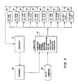
- FIGURE 3 is a block diagram of a control system according to the present invention;
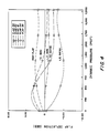
- FIGURE 4 is a graph of selected control surface deflections vs. dynamic pressure to maintain a selected roll rate with minimum drag under specified conditions for the aircraft of Figure 1;
- FIGURE 5 is a plan view of another embodiment according to the present invention of an aircraft with active flexible adaptive wings;
- FIGURE 6 is a front view of the aircraft of Figure 5;
- FIGURE 7 is a plan view of the aircraft of Figure 1 showing placement of various sensors; and
- FIGURE 8 is a block diagram of a control system which incorporates gust load alleviation stability augmentation, flutter suppression, and maneuver load control.
- While the invention will be described in connection with the preferred embodiments, it will be understood that it is not intended to limit the invention to those embodiments. On the contrary, it is intended to cover all alternatives, modifications, and equivalents that may be included within the spirit and scope of the invention as described by the appended claims.
- Referring now to Figures 1 and 2, there is shown an aircraft generally indicated at 10 having
wings fuselage 16. Mounted on the fuselage areengine inlets wing control surfaces wing control surfaces wing control surfaces wing control surfaces body control surfaces tail control surfaces - It should be noted that the
aircraft 10 does not include a horizontal tail. This is unnecessary with the present invention, thereby saving considerable weight and reducing aircraft observables. Thetail structures - While it is preferred that the
aircraft 10 not have a horizontal tail, this is not a requirement. The system would still provide many of the advantages discussed herein for an aircraft having horizontal tails. Similarly,aircraft 10 does not employ canards. However, the present invention could advantageously be used whether or not the aircraft has such surfaces. - All aircraft wings are flexible to a certain degree. There must, however, be sufficient stiffness and strength in the wings, even with an active control, to withstand design loads, maneuver loads, gusts, and to prevent flutter. Composite materials have seen recent application for wings due to their high strength to weight ratio and capability for aeroelastic tailoring. It is for these reasons that in the preferred embodiment, the
wings - Referring now to Figure 3 there is shown a block diagram of a control system according to the present invention. When the pilot desires that the aircraft execute a particular control movement, a
command signal 48 is generated (such as by stick movement) which is transmitted tocomputer 50. The command may be manual from the pilot or by automatic pilot.Computer 50 also receives signals fromsensors 46, which are positioned onaircraft 10.Sensors 46 provide signals indicative of motion of the aircraft. A number of parameters will be sensed in this regard. These will preferably include aircraft attitude, fuselage motion (accelerometer readings), altitude, and mach number. With gain scheduling for the particular aircraft included in the computer memory, the command signal and sensor signals, after suitable shaping, filtering, switching, conditioning, converting, surface command limiting, and combining are computed to determine optimal flap movements to cause the aeroelastic wing flexure which would result in the desired control movement. Control signals fromcomputer 50 are subsequently transmitted to actuators (not shown) for each of therespective flaps wings wings computer 50 such that the optimum wing shape forwings - The control system can also be used for providing active longitudinal stability augmentation to the
aircraft 10, which is particularly advantageous when there is no horizontal tail. This is accomplished in the same manner as described above with the exception that thecomputer 50 computes its control signals to maintain stability based only upon the signals fromsensors 46. However, when stability and flight control are required simultaneously,computer 50 would process all input signals to arrive at control signals which most efficiently accomplish both functions. Thus, thecomputer 50 can transmit control signals to the actuators for the control surfaces to produce (with minimum drag) under the current flight conditions a wing contour that provides aircraft longitudinal stability and/or a desired flight control movement.Tail control surfaces aircraft 10. - As an alternate to gain scheduling in the
computer 50, or in addition to such gain scheduling, a self adaptive concept can be used. This approach employs incremental movement of selected control surfaces with the resulting aircraft movement monitored and fed back to thecomputer 50. Based upon these feedback signals, thecomputer 50 will continually recalculate the optimal positions for the various control surfaces to cause the wing deflection which will result in the desired aircraft control. This could be combined with gain scheduling which would be used for initial positioning of the control surfaces. - The self adaptive concept also allows the system to compensate for a damaged or inoperative control surface. Since such a control surface would not bring about the expected control effect, the computer would search for a combination of control surface movements that does. Conversly, the loss of a control surface, such as an aileron, on a conventional aircraft, will normally severely impact aircraft control.
- With the ability to compensate for a damaged or inoperative control surface, the present invention results in another advantage, namely that less control redundancy is required. This would allow additional reductions in weight, complexity, and costs.
- Referring again to Figures 1 and 2, if the pilot generates a roll command which is intended to cause a certain roll rate,
computer 50 will transmit control signals to the various wing flaps (and optionally to the body flaps) to cause the aeroelastic contour ofwings wing 14 relative towing 12. This control technique will be unaffected by aileron reversal. In this regard, the present invention takes advantage of wing flexibility rather than opposing it. The control surfaces are used to twist each wing to obtain the desired wing contours to effect a desired control as opposed to being the primary control surfaces which must overcome opposing aeroelastic wing twist to effect the desired movement. This allows for a lighter weight wing (since less stiffness is required) and the elimination of a rolling tail which also saves wieght and reduces aircraft observables. - Figure 4 presents a graphic illustration in a particular design case for
wing 12 for a sixty-six degree per second roll rate at various dynamic pressures. The control surface deflections were derived based upon acheiving the desired roll rate for minimum drag. It should be noted that the trailing edge control surface deflections reverse direction as dynamic pressure increases. The control surfaces are being used beyond conventional aileron reversal. Also it should be noted that the maximum deflection of any control surface is never more than 5 degrees. Typical trailing edge control surface deflection on a conventional "stiff" wing design would be in arange 30 to 40 degrees to maintain the same roll rate. Thus, the present invention will result in a much lower drag during a maneuver than a conventional design. Also, due to the smaller control surface deflections required, the surface hinge movements will be reduced, resulting in smaller, lighter, and lower power actuators. - Pitch control for
aircraft 10 can be accomplished byflaps wings wings wings wings - The present invention can also be used to provide yaw control, whereby overall control for the aircraft is possible. This is illustrated in the embodiment shown in Figures 5 and 6. An aircraft generally indicated at 60 has
wings fuselage 66. Mounted on the fuselage areengine inlets Wing 62 employs leading edgewing control surfaces wing control surfaces Wing 64 employs leading edgewing control surfaces wing control surfaces aircraft 10, the wing control surfaces are able to deflect above and below the corresponding wing. Also likeaircraft 10,aircraft 60 does not include a horizontal tail. Further,aircraft 60 does not include a vertical tail. This again saves overall aircraft weight and reduces aircraft observables. - Yaw control for
aircraft 60 is provided by thewings wings Wings Wings wings wing tips wings wing tips wings aircraft 60. - A significant advantage of the present invention is the ability to configure the aircraft wings for substantially optimum performance under different flight conditions. Thus, optimal wing contour for transonic maneuver, supersonic cruise, landing and takeoff, and high speed acceleration vary substantially. The present invention is able to address this problem by significantly varying the shape of
wings wings - Referring now to Figure 7, there is shown a view of the
aircraft 10 of Figure 1 which illustrates an example of the placement of various sensors. Whileaircraft 10 is illustrated, the approach would also apply toaircraft 60.Sensors wing 12.Sensors wing 12.Sensors wing 14 andsensors wing 14. The sensors onwings Aircraft 10 also employsfuselage sensors Sensors wings - A plurality of other sensors designated 156 are also provided on the aircraft to measure roll, pitch, and yaw movement of the aircraft, lateral movement of the fuselage, mach number, and altitude. The nominal c.g. 164 for the aircraft is also illustrated. The term "nominal" is used since during flight, the aircraft actual center of gravity will shift, i.e., due to fuel usage. Accordingly what is meant by "nominal" is the average location of the center of gravity during flight.
- Figure 8 illustrates a block diagram of an enhanced control system for
aircraft 10 which incorporates the ability to compensate for maneuver load control, gust load alleviation, and flutter supression. Such a system allows for further reductions in wing weight and stiffness.Computer 200 receives pilot command signals 48 (when transmitted by the pilot or an automatic pilot) and signals from theoverall sensors 156,vertical fuselage sensors 202, andwings sensors 204.Vertical fuselage sensors 202 encompasssensors wing sensors 204 encompasssensors - When no maneuver load control, gust load alleviation, or flutter supression is required,
computer 200 will in response tosensors 156 andpilot command signal 48 perform the functions listed to compute optimal flap movements to cause the wing flexure which will maintain stability, produce desired control movements, and bring about optimum wing configuration for the particular flight conditions, e.g., supersonic cruise. Control signals fromcomputer 200 are subsequently transmitted to acutators (not shown) for each of therespective flaps wings wings computer 200 is preferably based upon providing optimum wing shape for thewings - When maneuver load control, gust load alleviation, or flutter suppression is necessary as determined by
computer 200 based upon the signals fromsensors wing 12 and/orwing 14 have been deflected due to flutter, gusts, and or maneuver loads, thecomputer 200 also processes such signals in combination with the signals fromoverall sensors 156 and anypilot command signal 48 to compute movements for the flaps. Thus, computed flap movements to effect stability augmentation and/or a desired control movement would be combined with computed flap movements necessary to compensate for maneuver load control, gust alleviation, or flutter suppression. If no control movement or stability augmentation is required at a given time when flutter suppression, maneuver load control, or gust alleviation is required, then the flaps will be moved bycomputer 200 solely to offset the detected maneuver loads, gusts, or flutter. - A self adaptive concept as discussed whith reference to Figure 3 may alternately or preferably be used in combination with gain scheduling for
computer 200. For desired control movements or optimum configuration for a given flight condition, thecomputer 200 would use feedback of resulting aircraft movement. For gusts, flutter, and maneuver loads,computer 200 would use feedback from the wing sensors to determine impact of the flap movements. - Thus, it is apparent that there has been provided, in accordance with the invention, an Aircraft Control System that fully satisfies the objectives, aims, and advantages set forth above. While the invention has been described in conjuction with specific embodiments thereof, it is evident that many alternatives, modifications, and variations will be apparent to those skilled in the art in light of the foregoing description. Accordingly, it is intended to embrace all such alternatives, modifications, and variations that fall within the spirit and scope of the appended claims.
- The invention involves using control surface movements in a manner to cause the wings to aeroelastically deflect into a desired overall contour to control the aircraft. Others in the prior art have also varied wing shape to obtain control, e.g., as disclosed in the Wright Brothers patent mentioned in the specification, U.S. Patent 3,310,261, and U.S. Patent 3,813,062. Unlike these prior art patents (as discussed in detail subsequently), the present invention accomplishes the bending and twisting of the wings aeroelastically by control surface movements as opposed to mechanical means. It should be appreciated, in view of these prior art patents and the present specification, that the desired aircraft control can be effected by deflecting the wings into a particular contour. See also U.S. Patent 4,330,100 wherein it is disclosed that wings are subjected to bending deformation and twist deformation as aerodynamic loads on the wings vary. As such, it should be clearly understood from the specification and claims that the desired aircraft control can be obtained by deflecting the wings into a contour which will bring about the desired aircraft control and that the wings are deflected aeroelastically (by aerodynamic loads) into the desired contour by selective movements of the wing control surfaces. As was pointed out above, movement of these flaps produces aerodynamic loads on the
wings wings - Pitch, roll, and yaw are controlled in accordance with the above, i.e. the wings of the aircraft are deflected into specific contours that will bring about the desired control, be it a pitch, roll, and/or yaw movement. It is well known in the art that such control movements are obtained by creating moments on the aircraft to bring about the desired control movement. See also the U.S. Patents mentioned previously which obtain control movements by selectively deflecting the aircraft wings. See also in the above specification the sample discussion relative to roll:
". . . if the pilot generates a roll command which is intended to cause a certain roll rate,computer 50 will transmit control signals to the various wing flaps (and optionally to the body flaps) to cause the aerolastic contour of thewings wing 14 relative towing 12." - Above it is further stated as an example that yaw control could be obtained by differentially deflecting
wing tips - The system of the ivnention is operative under conditions of roll reversal. Roll reversal occurs when in a conventionally controlled aircraft, the aircraft rolls in the opposite direction from the pilot commands, i.e., the conditions are such that the movement of the primary controll surfaces (ailerons) is overcome by the opposing aeroelastic wing twist. Under these conditions, the airplane, as controlled conventionally, would undergo roll reversal. However, with the present system, this situation does not occur since the control surfaces are used to induce wing twist which will result in the desired roll movement, i.e., wing twist is used to obtain the desired control as opposed to being compensated for and overcome by the meovement of the control surfaces. As noted above, this results in substantially smaller control surface deflections, which results in lower drag during maneuvers and lower poser actuation requirements. Further, a lighter weight wing can be used since less wing stiffness is required and a rolling tail eliminated.
- Flutter, gusts, and maneuver loads are detected as is conventional in the prior art with sensing devices such as
sensors - Regarding the operation of the computer to processes signals in order to cause stability of the aircraft, it should be understood that the invention is not the computer or a formula used by the computer to generate control signals to operate the flight control surfaces. Rather, the invention as claimed is to move the control surfaces on the wings in a manner to cause each of the wings to aeroelastically deflect into a desired overall contour to control the aircraft. The movements of the control surfaces to effect the particular wing contours and resulting aircraft control are calculated based upon flight conditions, i.e., sensed signals indicative of the motion of the aircraft. This is done by a conventional processor which would send signals to actuators (control means) representative of the desired control surface movements to aeroelastically effect the desired wing deflections. Deriving the algorithms for such a computer for a particula aircraft is clearly within the purview of one skilled in the art, i.e., under specified flight conditions with a desired control movement for a particular aircraft having known design characteristics, e.g., wing stiffness, the force that would be created on a wing and the resulting deflection by virtue of specific movements of particular control surfaces under the given flight conditions can be obtained. See also U.S. Patents 4,562,546 and 4,569,493 wherein there are made similar disclosures of conventional processing means.
Claims (28)
flight control surfaces mounted on said flexible wings; aircraft sensors for providing signals indicative of the motion of the aircraft;
processing means responsive to said signals from said aircraft sensors to generate control signals relative to control surface movements to aeroelastically effect desired wing deflections; and
control means receiving said control signals from said processing means for moving said control surfaces in accordance with said signals in a manner to cause each of said flexible wings to aeroelastically deflect into a desired overall contour to control the aircraft.
sensing motion of the aircraft; and
moving the control surfaces on said wings in response to the sensed motion of the aircraft in a manner to cause each of said wings to aeroelastically deflect into a desired overall contour to control the aircraft.
Priority Applications (2)
| Application Number | Priority Date | Filing Date | Title |
|---|---|---|---|
| EP86111669A EP0257123B1 (en) | 1986-08-22 | 1986-08-22 | Active flexible wing aircraft control system |
| DE8686111669T DE3676506D1 (en) | 1986-08-22 | 1986-08-22 | ACTIVE CONTROL SYSTEM OF AN AIRCRAFT WITH BENDABLE WING. |
Applications Claiming Priority (1)
| Application Number | Priority Date | Filing Date | Title |
|---|---|---|---|
| EP86111669A EP0257123B1 (en) | 1986-08-22 | 1986-08-22 | Active flexible wing aircraft control system |
Publications (2)
| Publication Number | Publication Date |
|---|---|
| EP0257123A1 true EP0257123A1 (en) | 1988-03-02 |
| EP0257123B1 EP0257123B1 (en) | 1991-01-02 |
Family
ID=8195363
Family Applications (1)
| Application Number | Title | Priority Date | Filing Date |
|---|---|---|---|
| EP86111669A Expired - Lifetime EP0257123B1 (en) | 1986-08-22 | 1986-08-22 | Active flexible wing aircraft control system |
Country Status (2)
| Country | Link |
|---|---|
| EP (1) | EP0257123B1 (en) |
| DE (1) | DE3676506D1 (en) |
Cited By (7)
| Publication number | Priority date | Publication date | Assignee | Title |
|---|---|---|---|---|
| US6766981B2 (en) | 2002-10-25 | 2004-07-27 | Northrop Grumman Corporation | Control system for alleviating a gust load on an aircraft wing |
| US20160200420A1 (en) * | 2014-09-25 | 2016-07-14 | Aurora Flight Sciences Corporation | System and method for unwanted force rejection and vehicle stability |
| US9963223B2 (en) | 2011-01-14 | 2018-05-08 | Lockheed Martin Corporation | Aerodynamic force sensing apparatus |
| CN110705153A (en) * | 2019-09-24 | 2020-01-17 | 中国航空工业集团公司沈阳飞机设计研究所 | Multi-order safety factor value taking method for unmanned aerial vehicle |
| CN112109876A (en) * | 2020-09-04 | 2020-12-22 | 北京航空航天大学 | Shape active control method based on static aeroelasticity effect of aircraft and aircraft adopting same |
| CN112394739A (en) * | 2020-10-29 | 2021-02-23 | 南京航空航天大学 | Active-deformation active-disturbance-rejection flight control method for four-rotor aircraft |
| CN115783241A (en) * | 2023-02-08 | 2023-03-14 | 中国空气动力研究与发展中心计算空气动力研究所 | Asynchronous deflection course control combined rudder control method of fusion body aircraft |
Families Citing this family (3)
| Publication number | Priority date | Publication date | Assignee | Title |
|---|---|---|---|---|
| CN102390524B (en) * | 2011-10-20 | 2013-08-28 | 西北工业大学 | Method for determining using priority of each control surface of multi-control-surface aircraft during over-the-horizon stage |
| CN102393749B (en) * | 2011-10-20 | 2014-04-02 | 西北工业大学 | Method for determining use priority of control surfaces of aircraft with multiple control surfces at take-off and landing stages |
| CN102431652B (en) * | 2011-10-20 | 2013-08-28 | 西北工业大学 | Method of determining use priority of various control surfaces of multi-control surface plane at close-range stage |
Citations (3)
| Publication number | Priority date | Publication date | Assignee | Title |
|---|---|---|---|---|
| GB191216890A (en) * | 1911-07-27 | 1913-04-17 | Rumpler Luftfahrzeugbau G M B | Improvements in Aeroplane Steering. |
| US4330100A (en) * | 1979-09-28 | 1982-05-18 | The United States Of America As Represented By The Administrator Of The National Aeronautics And Space Administration | Means for controlling aerodynamically induced twist |
| US4562546A (en) * | 1983-01-13 | 1985-12-31 | Rockwell International Corporation | Stability augmentation system for a forward swept wing aircraft |
-
1986
- 1986-08-22 EP EP86111669A patent/EP0257123B1/en not_active Expired - Lifetime
- 1986-08-22 DE DE8686111669T patent/DE3676506D1/en not_active Expired - Lifetime
Patent Citations (3)
| Publication number | Priority date | Publication date | Assignee | Title |
|---|---|---|---|---|
| GB191216890A (en) * | 1911-07-27 | 1913-04-17 | Rumpler Luftfahrzeugbau G M B | Improvements in Aeroplane Steering. |
| US4330100A (en) * | 1979-09-28 | 1982-05-18 | The United States Of America As Represented By The Administrator Of The National Aeronautics And Space Administration | Means for controlling aerodynamically induced twist |
| US4562546A (en) * | 1983-01-13 | 1985-12-31 | Rockwell International Corporation | Stability augmentation system for a forward swept wing aircraft |
Cited By (10)
| Publication number | Priority date | Publication date | Assignee | Title |
|---|---|---|---|---|
| US6766981B2 (en) | 2002-10-25 | 2004-07-27 | Northrop Grumman Corporation | Control system for alleviating a gust load on an aircraft wing |
| US9963223B2 (en) | 2011-01-14 | 2018-05-08 | Lockheed Martin Corporation | Aerodynamic force sensing apparatus |
| US20160200420A1 (en) * | 2014-09-25 | 2016-07-14 | Aurora Flight Sciences Corporation | System and method for unwanted force rejection and vehicle stability |
| CN110705153A (en) * | 2019-09-24 | 2020-01-17 | 中国航空工业集团公司沈阳飞机设计研究所 | Multi-order safety factor value taking method for unmanned aerial vehicle |
| CN110705153B (en) * | 2019-09-24 | 2023-09-05 | 中国航空工业集团公司沈阳飞机设计研究所 | Unmanned aerial vehicle multi-order safety coefficient value-taking method |
| CN112109876A (en) * | 2020-09-04 | 2020-12-22 | 北京航空航天大学 | Shape active control method based on static aeroelasticity effect of aircraft and aircraft adopting same |
| CN112109876B (en) * | 2020-09-04 | 2022-01-14 | 北京航空航天大学 | Shape active control method based on static aeroelasticity effect of aircraft and aircraft adopting same |
| CN112394739A (en) * | 2020-10-29 | 2021-02-23 | 南京航空航天大学 | Active-deformation active-disturbance-rejection flight control method for four-rotor aircraft |
| CN115783241A (en) * | 2023-02-08 | 2023-03-14 | 中国空气动力研究与发展中心计算空气动力研究所 | Asynchronous deflection course control combined rudder control method of fusion body aircraft |
| CN115783241B (en) * | 2023-02-08 | 2023-05-16 | 中国空气动力研究与发展中心计算空气动力研究所 | Asynchronous deflection course control combined rudder control method of fusion aircraft |
Also Published As
| Publication number | Publication date |
|---|---|
| EP0257123B1 (en) | 1991-01-02 |
| DE3676506D1 (en) | 1991-02-07 |
Similar Documents
| Publication | Publication Date | Title |
|---|---|---|
| US5082207A (en) | Active flexible wing aircraft control system | |
| US4479620A (en) | Wing load alleviation system using tabbed allerons | |
| US4598888A (en) | Fixed-wing aircraft with tandem supporting surfaces | |
| US4729528A (en) | Aeroelastic control flap | |
| EP3000722B1 (en) | Aircraft | |
| US5921506A (en) | Extendible leading edge flap | |
| US4455004A (en) | Flight control device for airplanes | |
| AU2018214162B2 (en) | System and method for optimizing horizontal tail loads | |
| US4146200A (en) | Auxiliary flaperon control for aircraft | |
| US7191985B2 (en) | Aircraft multi-axis modal suppression system | |
| US3734432A (en) | Suppression of flutter | |
| JPH08310495A (en) | Method and system of generating rudder correction command for reducing undesirable transverse motion | |
| US20050242234A1 (en) | Lifters, methods of flight control and maneuver load alleviation | |
| US3347498A (en) | Aircraft structural stress alleviators | |
| US4562546A (en) | Stability augmentation system for a forward swept wing aircraft | |
| EP0257123B1 (en) | Active flexible wing aircraft control system | |
| US3870253A (en) | Aircraft vectored flight control means | |
| AU2002326628A1 (en) | System and method for controlling an aircraft | |
| WO2003016133A1 (en) | System and method for controlling an aircraft | |
| US5722615A (en) | Transport airplane with front empennage | |
| US20020047069A1 (en) | Directional control and aerofoil system for aircraft | |
| US11273901B2 (en) | Method for controlling an aircraft, and an aircraft (variants) | |
| JPH07132893A (en) | Rotary-wing aircraft | |
| US2620150A (en) | Airplane control | |
| JP2524712B2 (en) | Equipment for controlling aircraft |
Legal Events
| Date | Code | Title | Description |
|---|---|---|---|
| PUAI | Public reference made under article 153(3) epc to a published international application that has entered the european phase |
Free format text: ORIGINAL CODE: 0009012 |
|
| AK | Designated contracting states |
Kind code of ref document: A1 Designated state(s): DE FR GB IT SE |
|
| 17P | Request for examination filed |
Effective date: 19880901 |
|
| 17Q | First examination report despatched |
Effective date: 19890721 |
|
| GRAA | (expected) grant |
Free format text: ORIGINAL CODE: 0009210 |
|
| AK | Designated contracting states |
Kind code of ref document: B1 Designated state(s): DE FR GB IT SE |
|
| ITF | It: translation for a ep patent filed |
Owner name: BARZANO' E ZANARDO ROMA S.P.A. |
|
| ET | Fr: translation filed | ||
| REF | Corresponds to: |
Ref document number: 3676506 Country of ref document: DE Date of ref document: 19910207 |
|
| PLBI | Opposition filed |
Free format text: ORIGINAL CODE: 0009260 |
|
| 26 | Opposition filed |
Opponent name: MESSERSCHMITT - BOELKOW - BLOHM GMBH, OTTOBRUNN Effective date: 19911002 |
|
| PLAB | Opposition data, opponent's data or that of the opponent's representative modified |
Free format text: ORIGINAL CODE: 0009299OPPO |
|
| R26 | Opposition filed (corrected) |
Opponent name: DEUTSCHE AEROSPACE AKTIENGESELLSCHAFT Effective date: 19911002 |
|
| PLBN | Opposition rejected |
Free format text: ORIGINAL CODE: 0009273 |
|
| STAA | Information on the status of an ep patent application or granted ep patent |
Free format text: STATUS: OPPOSITION REJECTED |
|
| 27O | Opposition rejected |
Effective date: 19920920 |
|
| EAL | Se: european patent in force in sweden |
Ref document number: 86111669.7 |
|
| REG | Reference to a national code |
Ref country code: GB Ref legal event code: IF02 |
|
| PGFP | Annual fee paid to national office [announced via postgrant information from national office to epo] |
Ref country code: GB Payment date: 20050817 Year of fee payment: 20 Ref country code: FR Payment date: 20050817 Year of fee payment: 20 |
|
| PGFP | Annual fee paid to national office [announced via postgrant information from national office to epo] |
Ref country code: SE Payment date: 20050819 Year of fee payment: 20 |
|
| PGFP | Annual fee paid to national office [announced via postgrant information from national office to epo] |
Ref country code: IT Payment date: 20050829 Year of fee payment: 20 |
|
| PGFP | Annual fee paid to national office [announced via postgrant information from national office to epo] |
Ref country code: DE Payment date: 20050930 Year of fee payment: 20 |
|
| PG25 | Lapsed in a contracting state [announced via postgrant information from national office to epo] |
Ref country code: GB Free format text: LAPSE BECAUSE OF EXPIRATION OF PROTECTION Effective date: 20060821 |
|
| REG | Reference to a national code |
Ref country code: GB Ref legal event code: PE20 |
|
| EUG | Se: european patent has lapsed |