EP0256845A2 - Überwachung der Abgase eines Düsenflugzeugmotors - Google Patents
Überwachung der Abgase eines Düsenflugzeugmotors Download PDFInfo
- Publication number
- EP0256845A2 EP0256845A2 EP19870307128 EP87307128A EP0256845A2 EP 0256845 A2 EP0256845 A2 EP 0256845A2 EP 19870307128 EP19870307128 EP 19870307128 EP 87307128 A EP87307128 A EP 87307128A EP 0256845 A2 EP0256845 A2 EP 0256845A2
- Authority
- EP
- European Patent Office
- Prior art keywords
- engine
- sensor
- sensors
- charge
- detecting means
- Prior art date
- Legal status (The legal status is an assumption and is not a legal conclusion. Google has not performed a legal analysis and makes no representation as to the accuracy of the status listed.)
- Withdrawn
Links
Images


Classifications
-
- G—PHYSICS
- G01—MEASURING; TESTING
- G01N—INVESTIGATING OR ANALYSING MATERIALS BY DETERMINING THEIR CHEMICAL OR PHYSICAL PROPERTIES
- G01N27/00—Investigating or analysing materials by the use of electric, electrochemical, or magnetic means
- G01N27/62—Investigating or analysing materials by the use of electric, electrochemical, or magnetic means by investigating the ionisation of gases, e.g. aerosols; by investigating electric discharges, e.g. emission of cathode
- G01N27/626—Investigating or analysing materials by the use of electric, electrochemical, or magnetic means by investigating the ionisation of gases, e.g. aerosols; by investigating electric discharges, e.g. emission of cathode using heat to ionise a gas
Definitions
- the present invention relates to the condition monitoring of a jet engine.
- the signal monitored in accordance with the present invention is the rate of change of charge measured by the electrode with respect to some datum (ground) level. This signal will hereinafter be referred to as a "pulse" signal.
- the integrated pulse signal is the total amount of the charge induced in the sensor by a given incident and this is referred to hereinafter as the "charge" signal.
- the plurality of sensors may be disposed about the periphery of the exhaust duct of an engine, typically to define an annular sensor array.
- a number of sensors may be incorporated in the engine either upstream or downstream of the combustor units.
- the detecting means may include comparison means for comparing dominant frequencies sensed by said sensing means.
- the charge signal is derived by electronically integrating the pulse signal detected by the detector means.
- the sensors for use in the invention may comprise an arcuate conducting surface, mounting means for mounting said surface in the exhaust duct of an engine, electrical insulating means serving to isolate said surface from the body of the engine, and conducting means for connecting said surface to detecting means externally of the engine casing, the arrangement being such that when the engine is in use, the presence of electrically charged debris in the exhaust gas stream in the duct induces a charge on said conducting surface.
- the insulating means may be a layer of ceramic material provided on a surface thereof.
- the ceramic material of the arcuate plate is preferably juxtaposed the internal surface of the exhaust duct.
- the mounting means may comprise a stud connected with said surface, insulating means carrying said stud to locate the same and to isolate the stud electrically from the surroundings.
- a sensor array may define a substantially cylindrical surface, each sensor extending over a circumferential portion of a segment of the duct within which the array is located.
- the sensors are accurate; they may be planar or any other shape, preferably corresponding to the contours of the passage in which they are located.
- a sensor array may be inserted in the exhaust duct of a gas turbine engine by applying initially an insulating layer to the internal surface of said exhaust duct and applying a metallic layer to the insulating layer.
- the effective thickness of the assembly is markedly reduced, thereby reducing any trimming effect on the gas path within the engine under working conditions. Furthermore, vibration effects on the probe will be substantially reduced.
- the use of a plurality of sensors particularly in the exhaust duct gives a plurality of signals and the time displacement and amplitude variation of the signals as recorded by the various segments of ring probe can given an indication of the general area of the engine in which the fault or problems lies.
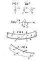
- a group of charged particles 11 is expelled from the area of the distress within the engine.
- the group of charged particles passes as a charge cloud in the gas path and as it approaches the ring sensor 10, it induces an electrostatic charge therein.
- the particles 11 are moving at a high velocity and the induced charge increases rapidly as the particles approach the plane of the ring sensor 10.
- the rate of change of charge increases and reaches a maximum as the leading edge of the cloud enters the plane of the sensor array. Assuming that the powder cloud has approximately uniform charge per unit length, the rate of change of charge decreases and reaches zero when the centre of the cloud is coincident with the centre of the sensor array. The maximum charge has then been induced.
- the rate of change of charge continues to fall as the leading edge of the cloud is leaving the vicinity of the sensors and reaches a minimum when the trailing edge leaves the sensors again indicating a rapid rate of change of charge.
- the signal level then returns to the mean level due to the discharge time constant in the electronics associated with the means for sensing the charge induced on the electrodes.
- the signal between the two peaks is not uniform showing almost a point of inflection. This mainly occurs for ring sensor arrays which is wider than any other sensors where the charge cloud is large and is not uniformally dispersed thereby causing some momentarily rate of change of charge.
- the charge signal as hereinbefore defined is the integrated pulse signal and shows the amount of charge induced on the sensor and hence the maximum of the charge signal should coincide with zero crossing of the pulse signal (no rate of change of charge). There is evidently a small time lag between the pulse and the charge signals and this is due to the charge constant of the integrator circuit and does not detract from the usefulness of the signal.
- the amount of charge induced thereon increases and reaches a maximum where the centre of the cloud is at the centre of the sensor. This corresponds to the first half of the bi-polar pulse signal.
- the quantum of charge induced on the electrode is at its maximum as shown by point B in Figure 2B.
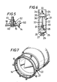
- FIG. 7 A typical series of sensors as arranged in the exhaust gas duct of a jet engine is shown in Figure 7 and the individual sensors are shown in Figures 3 and 4. In particular configuration shown in Figure 7, four segmental sensors are employed. Each sensor comprises an arcuate plate 14 having a pair of arcuately spaced holes 15. The face 16 of plate 14 is polished to provide a charge receiving surface and the periphery 17 and the back 18 (see Figure 4) are covered with a coating of a ceramic, electrically insulating material.
- Each plate 14 is secured to the engine casing 20 by means of a securing stud assembly 21.
- the securing stud assembly is shown in Figure 6 and comprises a generally cylindrical sleeve 22 which is provided on its internal surface towards a first end with an annulus 23. The external surface of the first end is threaded at 24 and the second end 25 of stud assembly 21 is provided with an annular recess (not shown).
- the second end is adapted to accommodate an insulating member 26 formed of a ceramic material and having a central bore adapted to accommodate a metal screw 27 adapted to be secured by nut 28 to ceramic member 26.
- Bolt 27 is provided with an enlarged slot 30 at its threaded end and is adapted to receive a flatten portion 31 of stud 32.
- Stud 32 is generally cylindrical and is threaded at its first end 33 and is adapted to be engaged by nut 34 which serves to clamp a further ceramic block 35 between the shoulder 36 defined by constriction 23 against ceramic member 26.
- the head 29 of bolt 27 serves to retain plate 16 in closely spaced relationship with the casing, but insulated therefrom while the bolt 27 and its associates stud 32 serves to provide a means of electrical connection whereby the end 33 can be electrically connected to a conductor for connection to detection sensing and analytical equipment.
- the ring sensor in accordance with the present invention may also be used in conjunction with rod sensors which are provided in the turbo fan casing for analysis of any debris present within the turbine casing itself. (See Figures 8 and 8a).
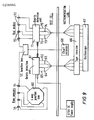
- the ring sensors 18 are connected via a four way function box 60 to supply signals to a debris detection unit 61.
- the debris detection unit has a channel corresponding to each ring sensor and provides four outputs 62, 63, 64 and 65 each of which are connected to a tape recorder 66 and subsequently to an oscilloscope 67 to provide a visual indication of the output of the components.
- the debris detection unit also provides an output to a chart recorder 68.
- Rod sensors 70 are also connected to a debris detection unit 71 and the various putputs 72, 73, 74 and 75 are connected to tape recorder 66 and 67 and are switchable to chart recorder 68.
- the debris detection unit 61 comprises a current input (trans-resistant) amplifier A which is an AC coupled amplifier with the gains set by resistor R (see Figure 10). Different types of sensor installation require different settings of R, the sensor signal passes also via capacitor 81. The non-inverting terminal is connected to the engine casing. The output signal at 82 passes to the input to a differential amplifier B which removes common mode signals present between the engine casing and the equipment earth. The differential amplifier output is a signal representing the rate at which the charge enters or leaves the sensor region. This is the pulse signal shown in Figure 2 which is then passed to a pulse outlet socket 83 for subsequent processing or tape recording.
- the pulse signal may also be passed to an integrating stage C, which for a ring sensor, the time integral of the pulse signal represents the amount of charge induced on the sensor.
- This signal is available via a further output 84 as a "charge" output. While this signal does not have the same physical significance for rod and ring sensors, the low pass filtering action for the integrator aids noise and interference removal.
- the integrator C is selectable between 1 and 10 seconds and this provides a smoothing charge output which can be separately monitored.
- test engine was fitted with a CA902 accelerometer mounted in the standard position.
- Extra instrumentation fitted by Rolls Royce to try to detect the faulty blade was as follows:-
- the engine was first run in standard form to give a datum record for the detectable signals.
- the test procedure was as follows:-
- the engine was stripped and rebuilt with a faulty blade in a fourth stage compressor rotor.
- the tang root of the blade was partially cut through to try and simulate the effects of cracking. The intention was that the blade would be sufficiently faulty to cause it to lean and produce a tip rub at some stage of the engine accleration. The root was not completely cut through as this would cause loss of the blade from the disc.
- the test programme was as follows:-
- thermocouples monitored temperatures of 250°C on the rod sensor shield and 325°C on the ring sensor shield.
- the cables and connections have been selected so as not to be damaged by the high temperatures involved.
- the ring sensor measured a lot of electrostatic activity including regular frequency pulses corresponding to ignitors operating.
- the signal level reached about 1.75V maximum during the start-up and this high level of activity remained until the engine had reached about until the engine had reached about 25% speed.
- the background level then settled down to about 30mt peak to peak and increased to about 40mV peak to peak at engine idle, i.e. 40% rpm.
- the background level gradually increased. At approximately 85% speed, it was about 70mV peak to peak. Above this speed the peak to peak amplitude increased more rapidly reaching 120mV at 93% rpm and about 200mV at 104% rpm.
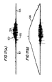
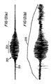
- Each recording A and B is a record of the output from a single plate 14 of the ring sensor assembly shown in Figure 8.
- the particular trace illustrated is of the engine run-up to maximum speed and then throttled back.
- the initial signal 101 obtained during the initial run-up period of 40 to 80% power shows very few vibrations and little sign of engine stress.
- the power exceeds 80% of maximum output the number of charged particles in the exhaust duct begins to increase as shown by signal in area 102.
- the number of specific peaks 103 are to be noted as the engine approaches full power.
- the rate of change of charge from the particles within the system decreases back to a level where they are only just detectable at 105.
- the additional trace 106 on trace B is a tachometer reading which is a measure of engine speed superimposed over the detected charge pattern for the particular ring sensor.
- This level fluctuated slightly while the engine remained at 104% rpm and decreased a small amount as the deceleration regime commenced. Then reduced sharply at about 96% of speed, gradually reducing to a background level similar to the acceleration case at 90% rpm. This pattern was repeated when second and third acceleration/deceleration cycles were carried out, although the maximum peak to peak amplitude was slightly less than for the first acceleration/deceleration.
- Figure 12 shows the trace for ring segments 1 and 2 similar to Figure 11.
- the general signal level on the blade rub test is high throughout the cycle, for example at 40% rpm, it is 60mV on the blade rub test compared with 40mV on the datum test and at 90% rpm it is 160mV peak to peak on the rub test compared with 120mV peak to peak on the datum run.
- the rate of change of signal level between these two speeds on datum and rub tests is about the same, being a factor of 3 on the datum test and 2.7 on the rub test.
- the rate of change of signal level and, therefore, electrostatic charge in the exhaust cone between about 97% rpm and 104% on the rub test is much greater than the datum test, a factor of about 3 on the rub test to about 1.6 during the datum test.
- the method of the invention gave a clear indication of distress within the engine. Furthermore, the method of detection of the use of the plurality of sensors provided the opportunity to carry out further analysis of the information.
- the information collected in accordance with the invention is capable of further analysis to show that during distress of the engine releasing metal particles into the gas stream, there was a change
- a method of the invention provides for signal analysis techniques including signal averaging, fast fourier transform analysis, signal statistics, signal shape identification, threshold crossings.
- the invention thus provides the opportunity to fit sensors in accordance with the present invention into both existing and new jet engines to provide an in-flight indication of any severe distress in the engine. It also provides the possibility of second line analysis whereby a flight record of the engine performance may be monitored and then at the end of the flight, may be run through a computer diagnostic for that particular engine to give an indication of the severity and location of any distresses monitored during flight.
- the present invention also allows for the possibility of integration of electrostatic distress sensing techniques for condition monitoring along with other techniques.
Landscapes
- Chemical & Material Sciences (AREA)
- Chemical Kinetics & Catalysis (AREA)
- Electrochemistry (AREA)
- Physics & Mathematics (AREA)
- Health & Medical Sciences (AREA)
- Life Sciences & Earth Sciences (AREA)
- Analytical Chemistry (AREA)
- Biochemistry (AREA)
- General Health & Medical Sciences (AREA)
- General Physics & Mathematics (AREA)
- Immunology (AREA)
- Pathology (AREA)
- Testing Of Engines (AREA)
- Investigating Or Analyzing Materials By The Use Of Electric Means (AREA)
- Investigating Or Analyzing Materials By The Use Of Fluid Adsorption Or Reactions (AREA)
Applications Claiming Priority (4)
| Application Number | Priority Date | Filing Date | Title |
|---|---|---|---|
| GB868620239A GB8620239D0 (en) | 1986-08-20 | 1986-08-20 | Jet engine gas path conditioning monitoring |
| GB8620239 | 1986-08-20 | ||
| GB8702553 | 1987-02-05 | ||
| GB878702553A GB8702553D0 (en) | 1987-02-05 | 1987-02-05 | Jet engine gas path condition monitoring |
Publications (1)
| Publication Number | Publication Date |
|---|---|
| EP0256845A2 true EP0256845A2 (de) | 1988-02-24 |
Family
ID=26291197
Family Applications (2)
| Application Number | Title | Priority Date | Filing Date |
|---|---|---|---|
| EP87307129A Withdrawn EP0256846A3 (de) | 1986-08-20 | 1987-08-12 | Überwachung der Abgase eines Düsenflugzeugmotors |
| EP19870307128 Withdrawn EP0256845A2 (de) | 1986-08-20 | 1987-08-12 | Überwachung der Abgase eines Düsenflugzeugmotors |
Family Applications Before (1)
| Application Number | Title | Priority Date | Filing Date |
|---|---|---|---|
| EP87307129A Withdrawn EP0256846A3 (de) | 1986-08-20 | 1987-08-12 | Überwachung der Abgase eines Düsenflugzeugmotors |
Country Status (1)
| Country | Link |
|---|---|
| EP (2) | EP0256846A3 (de) |
Cited By (8)
| Publication number | Priority date | Publication date | Assignee | Title |
|---|---|---|---|---|
| GB2266772A (en) * | 1992-04-30 | 1993-11-10 | Pollution Control & Measuremen | Detecting particles in a gas flow triboelectrically. |
| WO1994012872A1 (en) * | 1992-11-30 | 1994-06-09 | Stewart Hughes Limited | A sensor |
| US5753632A (en) * | 1993-04-07 | 1998-05-19 | Schmidt; Alfred | Use of colloidal silica for the treatment of sickle-cell anaemia, malaria and exogenously induced leucopenias |
| GB2336434A (en) * | 1998-04-17 | 1999-10-20 | Stewart Hughes Ltd | An apparatus for and method of monitoring a rotating machine |
| US6192740B1 (en) | 1993-04-06 | 2001-02-27 | Pcme Limited | Method and apparatus for detecting particles in a flow |
| EP1596037A2 (de) | 2004-05-13 | 2005-11-16 | ROLLS-ROYCE plc | Schaufelanordnung |
| KR20160146875A (ko) * | 2014-04-24 | 2016-12-21 | 누보 피그노네 에스알엘 | 회전 터보기계 내에서 회전 부품과 고정 부품 사이의 마찰을 모니터링하는 방법, 모니터링 장치 및 터보기계 |
| US10900377B2 (en) | 2018-04-23 | 2021-01-26 | Honeywell International Inc. | System and method for monitoring for sand plugging in gas turbine engines |
Families Citing this family (2)
| Publication number | Priority date | Publication date | Assignee | Title |
|---|---|---|---|---|
| GB8707187D0 (en) * | 1987-03-25 | 1987-04-29 | Hughes Ltd Stewart | Monitoring of foreign object in engines |
| GB8901238D0 (en) * | 1989-01-20 | 1989-03-15 | Stewart Hughes Ltd | Improvements relating to charge sensors |
Family Cites Families (2)
| Publication number | Priority date | Publication date | Assignee | Title |
|---|---|---|---|---|
| US3775763A (en) * | 1972-03-07 | 1973-11-27 | Us Air Force | Apparatus for indicating the impending failure of a jet engine |
| US4584531A (en) * | 1982-10-04 | 1986-04-22 | United Technologies Corporation | Noncontact electrostatic hoop probe for combustion engines |
-
1987
- 1987-08-12 EP EP87307129A patent/EP0256846A3/de not_active Withdrawn
- 1987-08-12 EP EP19870307128 patent/EP0256845A2/de not_active Withdrawn
Cited By (11)
| Publication number | Priority date | Publication date | Assignee | Title |
|---|---|---|---|---|
| GB2266772A (en) * | 1992-04-30 | 1993-11-10 | Pollution Control & Measuremen | Detecting particles in a gas flow triboelectrically. |
| GB2266772B (en) * | 1992-04-30 | 1995-10-25 | Pollution Control & Measuremen | Detecting particles in a gas flow |
| US5591895A (en) * | 1992-04-30 | 1997-01-07 | Pollution Control & Measurement (Europe) Ltd. | Detecting particles in a gas flow |
| WO1994012872A1 (en) * | 1992-11-30 | 1994-06-09 | Stewart Hughes Limited | A sensor |
| US6192740B1 (en) | 1993-04-06 | 2001-02-27 | Pcme Limited | Method and apparatus for detecting particles in a flow |
| US5753632A (en) * | 1993-04-07 | 1998-05-19 | Schmidt; Alfred | Use of colloidal silica for the treatment of sickle-cell anaemia, malaria and exogenously induced leucopenias |
| GB2336434A (en) * | 1998-04-17 | 1999-10-20 | Stewart Hughes Ltd | An apparatus for and method of monitoring a rotating machine |
| EP1596037A2 (de) | 2004-05-13 | 2005-11-16 | ROLLS-ROYCE plc | Schaufelanordnung |
| KR20160146875A (ko) * | 2014-04-24 | 2016-12-21 | 누보 피그노네 에스알엘 | 회전 터보기계 내에서 회전 부품과 고정 부품 사이의 마찰을 모니터링하는 방법, 모니터링 장치 및 터보기계 |
| US10161785B2 (en) | 2014-04-24 | 2018-12-25 | Nuovo Pignone Srl | Method of monitoring rubbing between a rotary party and a stationary part in a rotating turbomachine, monitoring arrangement and turbomachine |
| US10900377B2 (en) | 2018-04-23 | 2021-01-26 | Honeywell International Inc. | System and method for monitoring for sand plugging in gas turbine engines |
Also Published As
| Publication number | Publication date |
|---|---|
| EP0256846A3 (de) | 1990-05-02 |
| EP0256846A2 (de) | 1988-02-24 |
Similar Documents
| Publication | Publication Date | Title |
|---|---|---|
| US6456945B1 (en) | Detecting anomalies in rotating components | |
| Zielinski et al. | Noncontact vibration measurements on compressor rotor blades | |
| US4335600A (en) | Detecting internal abnormalities in turbines | |
| US5097711A (en) | Shrouded turbine blade vibration monitor and target therefor | |
| US4380172A (en) | On-line rotor crack detection | |
| Heath et al. | A survey of blade tip-timing measurement techniques for turbomachinery vibration | |
| US6904371B2 (en) | Method and apparatus for measuring rotor unbalance | |
| US4888948A (en) | Monitoring of foreign object ingestion in engines | |
| US20060283190A1 (en) | Engine status detection with external microphone | |
| US20110213569A1 (en) | Method and device for detecting cracks in compressor blades | |
| US7323868B2 (en) | System and method for temperature independent measurement of standoff distance using an eddy current sensor | |
| US5497101A (en) | Device for effecting dynamic measurement of the distance between the facing faces of the rotor and the stator of a rotary machine | |
| EP0256845A2 (de) | Überwachung der Abgase eines Düsenflugzeugmotors | |
| Joung et al. | Analysis of vibration of the turbine blades using non-intrusive stress measurement system | |
| RU2686522C2 (ru) | Способ мониторинга в режиме реального времени рабочего состояния емкостного датчика | |
| CN108303648A (zh) | 发电机大轴运行状态的监测装置及其监测方法 | |
| Cardwell et al. | The use of eddy current sensors for the measurement of rotor blade tip timing: sensor development and engine testing | |
| Krause et al. | Asynchronous response analysis of non-contact vibration measurements on compressor rotor blades | |
| Ugwiri et al. | Vibrations for fault detection in electric machines | |
| US9689660B2 (en) | Method and device for monitoring status of turbine blades | |
| Szczepanik et al. | Tip-timing and tip-clearance for measuring rotor turbine blade vibrations | |
| US4951500A (en) | Method for determining the untwist of turbine blades | |
| Fan et al. | Research on running status monitoring and rotating blade crack detection of large-scale centrifugal compressor based on blade tip timing technique | |
| CN207799037U (zh) | 发电机大轴运行状态的监测装置、发电机大轴和汽轮机 | |
| Tamura et al. | Non-contact vibration measurement of the rotor blades that play a pivotal role in the reliability of gas turbines |
Legal Events
| Date | Code | Title | Description |
|---|---|---|---|
| PUAI | Public reference made under article 153(3) epc to a published international application that has entered the european phase |
Free format text: ORIGINAL CODE: 0009012 |
|
| AK | Designated contracting states |
Kind code of ref document: A2 Designated state(s): AT BE CH DE ES FR GB GR IT LI LU NL SE |
|
| STAA | Information on the status of an ep patent application or granted ep patent |
Free format text: STATUS: THE APPLICATION IS DEEMED TO BE WITHDRAWN |
|
| 18D | Application deemed to be withdrawn |
Effective date: 19900301 |
|
| RIN1 | Information on inventor provided before grant (corrected) |
Inventor name: FORFITT, ROY Inventor name: FISHER, CELIA ELIZABETH |