EP0256796A2 - Verfahren und Vorrichtung zum gesteuerten Richtbohren von Bohrungen - Google Patents
Verfahren und Vorrichtung zum gesteuerten Richtbohren von Bohrungen Download PDFInfo
- Publication number
- EP0256796A2 EP0256796A2 EP87306999A EP87306999A EP0256796A2 EP 0256796 A2 EP0256796 A2 EP 0256796A2 EP 87306999 A EP87306999 A EP 87306999A EP 87306999 A EP87306999 A EP 87306999A EP 0256796 A2 EP0256796 A2 EP 0256796A2
- Authority
- EP
- European Patent Office
- Prior art keywords
- force
- drill string
- acting
- sensors
- measurements
- Prior art date
- Legal status (The legal status is an assumption and is not a legal conclusion. Google has not performed a legal analysis and makes no representation as to the accuracy of the status listed.)
- Granted
Links
Images
Classifications
-
- E—FIXED CONSTRUCTIONS
- E21—EARTH OR ROCK DRILLING; MINING
- E21B—EARTH OR ROCK DRILLING; OBTAINING OIL, GAS, WATER, SOLUBLE OR MELTABLE MATERIALS OR A SLURRY OF MINERALS FROM WELLS
- E21B7/00—Special methods or apparatus for drilling
- E21B7/04—Directional drilling
-
- E—FIXED CONSTRUCTIONS
- E21—EARTH OR ROCK DRILLING; MINING
- E21B—EARTH OR ROCK DRILLING; OBTAINING OIL, GAS, WATER, SOLUBLE OR MELTABLE MATERIALS OR A SLURRY OF MINERALS FROM WELLS
- E21B47/00—Survey of boreholes or wells
- E21B47/007—Measuring stresses in a pipe string or casing
-
- E—FIXED CONSTRUCTIONS
- E21—EARTH OR ROCK DRILLING; MINING
- E21B—EARTH OR ROCK DRILLING; OBTAINING OIL, GAS, WATER, SOLUBLE OR MELTABLE MATERIALS OR A SLURRY OF MINERALS FROM WELLS
- E21B47/00—Survey of boreholes or wells
- E21B47/02—Determining slope or direction
- E21B47/022—Determining slope or direction of the borehole, e.g. using geomagnetism
Definitions
- a so-called “big eye” drill bit is selectively oriented in a borehole to direct an enlarged port in the bit in a given lateral direction. Then, while rotation of the bit is temporarily discontinued, the mud pumps are operated for forcibly discharging a jet of drilling mud from the enlarged port to progressively carve out a cavity in the adjacent sidewall of the borehole into which the bit will hopefully advance whenever rotation is resumed.
- a third common directional drilling technique employs a fluid-driven motor and earth-boring device that are coupled to a so-called "bent sub" which can be cooperatively controlled from the surface for selectively positioning the device to drill along any one of several courses of excavation.
- MWD measuring-while-drilling
- directional measurements are obtained by arranging a MWD tool to include typical directional instruments adapted to provide real-time measurements representative of the spatial position of the tool in a borehole.
- typical directional instruments adapted to provide real-time measurements representative of the spatial position of the tool in a borehole.
- a conventional drill bit when a conventional drill bit is combined with a MWD tool which can provide either or both of these real-time measurements, it can be determined whether at least limited downhole directional changes are being effected from the surface by varying one or more drilling parameters such as the rotational speed of the drill string, the flow rate of the drilling mud in the drill string and the load on the drill bit.
- the ability to make these real-time directional or bending-moment measurements has also made it feasible to combine either a big-eye bit or a drilling motor coupled to a controllable bent sub with a suitable MWD tool for continuously monitoring the directional drilling tool as it excavates a borehole. It should be noted in passing that it has been found advantageous to employ MWD tools capable of providing real-time directional measurements while drilling a deviated borehole or while drilling a borehole along a generally vertical course of excavation.
- the instrumentation section of a typical MWD tool is ordinarily separated from the drilling apparatus by various tool bodies and, in some instances, one or more drill collars as well. Accordingly, when a directional measurement is made, the drilling apparatus is already at an advanced location that the measuring instruments will not reach until perhaps several hours later. In other words, any particular directional measurement represents only the previous location of the drilling apparatus when it was drilling the borehole interval that is presently occupied by the directional instrumentation in the MWD tool. Since the several interconnecting bodies and drill collars are relatively flexible, the drilling apparatus can be easily diverted from its intended course of excavation by such things as variations in formation properties or in the borehole environment or by changes in the performance characteristics of the drilling apparatus.
- the new and improved measuring apparatus of the present invention includes direction-measuring means for determining the present azimuthal direction and angular inclination of the earth-boring apparatus and producing one or more output signals representative of the spatial position of the boring apparatus.
- the measuring apparatus also includes force-measuring means for producing one or more output signals representative of the bending moments and shear forces acting on the measuring apparatus at a designated location above the earth-boring apparatus.
- the measuring apparatus further includes circuit means for combining these output signals to determine the magnitude and direction of any forces tending to divert the earth-boring apparatus.
- the measuring apparatus also includes means for cooperatively utilizing these output signals to direct the earth-boring apparatus along a selected course of excavation.
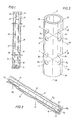
- FIGURE 1 a preferred embodiment of a new and improved directional drilling tool 10 arranged in keeping with the principles of the present invention is shown dependently coupled to the lower end of a tubular drill string 11 comprised of one or more drill collars, as at 12, and a plurality of tandemly-connected joints of drill pipe as at 13.
- the new and improved directional drilling tool 10 includes earth-boring means such as a fluid-powered turbodrill or a conventional drill bit as at 14 for excavating a borehole 15 through various earth formations as at 16.
- the drill string 11 is rotated by a typical drilling rig (not shown) at the surface as substantial volumes of a suitable drilling fluid such as a so-called “drilling mud" are continuously pumped downwardly through the drill string (as shown by the arrow 17).
- the drilling mud is discharged from fluid ports in the drill bit 14 for cooling it as well as for carrying formation materials removed by the bit to the surface as the drilling mud returns upwardly (as shown by the arrow 18) by way of the annular space in the borehole 15 outside of the drill string 11.
- the directional drilling tool 10 further comprises a typical MWD tool 19 which is preferably arranged with a plurality of heavy-walled tubular bodies which are tandemly coupled together to enclose new and improved force-measuring means 20 of the invention adapted for measuring various forces acting on the directional tool, typical position-measuring means 21 adapted for measuring one or more parameters indicative of the spatial position of the directional tool and typical data-signalling means 22 adapted for transmitting encoded acoustic signals to the surface through the downwardly-flowing mud stream in the drill string 11 that are representative of the output signals respectively provided by the force-measuring means and the position-measuring means.
- a typical MWD tool 19 which is preferably arranged with a plurality of heavy-walled tubular bodies which are tandemly coupled together to enclose new and improved force-measuring means 20 of the invention adapted for measuring various forces acting on the directional tool
- typical position-measuring means 21 adapted for measuring one or more parameters indicative of the spatial position
- the MWD tool 19 may also include one or more additional sensors and circuitry (not shown) as are typically employed for measuring various downhole conditions such as electrical or radioactivity properties of the adjacent earth formations and the temperature of the drilling mud.
- the output signals representative of each of these several measurements will be sent to the surface by way of the data-transmitting means 22 where they will be detected and processed by appropriate surface apparatus (not shown in the drawings).
- the MWD tool 19 as well as the surface detecting-and-processing apparatus are respectively arranged in the same fashion as the downhole and surface apparatus disclosed in the aforementioned Tanguy patents which, along with the other patents described therein, are herein incorporated by reference.
- it is preferred to employ a MWD tool as described in the Tanguy patents it will be realized that other telemetry systems such as those systems mentioned in the Tanguy patents could also be utilized for practicing the new and improved methods of the present invention.
- FIGURE 2 a somewhat-simplified diagram is shown of the new and improved directional drilling tool 10, the lower portion of the drill string 11 above the tool and the drill bit 14 therebelow for schematically illustrating some of the forces which may be acting on this assembly during a typical drilling operation.
- F1 a downward force
- F2 a downward force
- a significant aspect of the present invention is particularly directed toward providing new and improved methods and apparatus for accurately determining the magnitude and direction of the bending moment Mb acting on the drill bit 14 at any time during the course of a typical drilling operation.
- the external body 24 of the new and improved force-measuring means 20 is depicted somewhat schematically to illustrate the spatial relationships of the several measurement axes of the body as the force-measuring means measure various dynamic forces acting on the directional drilling tool 10 during a typical drilling operation.
- the thick-walled tubular body 24 is cooperatively arranged as a separate sub that can be mounted just above the drill bit 14 for obtaining more accurate measurements of the various forces acting on the bit.
- housings such as, for example, those shown in U.S. Patent No. 3,855,857 or U.S. Patent No. 4,359,898 could be used as depicted there or with modification as needed for devising alternative embodiments of force-measuring apparatus also falling within the scope of the present invention.
- the body 24 has a longitudinal or axial bore 25 of an appropriate diameter for carrying the stream of drilling mud flowing through the drill string 11.
- the body 24 has an upper set of four lateral or radial openings, as at A1, A2, A3 and A4, which are spaced equally around the circumference of the tubular body with the central axes of these openings lying in a common transverse plane that perpendicularly intersects the longitudinal or central Z-axis 26 of the body.
- the body 24 is also provided with a lower set of radial openings, as at B1, B2, B3 and B4, respectively disposed directly below their counterparts in the upper set of openings, A1-A4, and having their axes all lying in a lower transverse plane that is parallel to the upper transverse plane and also perpendicularly intersects the longitudinal Z-axis 26 of the body.
- these openings are cooperatively positioned so that they are respectively aligned with one another in either an upper or a lower transverse plane that perpendicularly intersects the Z-axis 26 of the body.
- one pair of the upper holes, A1 and A3 are respectively located on opposite sides of the body 24 and axially aligned with each other so that their respective central axes lie in the upper transverse plane and together define an X-axis 27 that is perpendicular to the Z-axis 26 of the body.
- the other two openings A2 and A4 in the upper plane are located on diametrically-opposite sides of the body 24 and are angularly offset by 90-degrees from the first set of openings A1 and A3 so that their aligned central axes respectively define the Y-axis 28 in the upper plane, with this upper Y-axis being perpendicular to the Z-axis 26 as well as the upper X-axis 27.
- one opposed pair of the openings B1 and B3 is arranged to define the X-axis 29 in the lower plane and the other opposed pair of openings B2 and B4 are arranged to define the Y-axis 30 in the lower plane.
- the upper openings A1 and A3 are positioned directly over their counterpart lower openings B1 and B3 so that the upper X-axis 27 is parallel to the lower X-axis: 29 and thereby define a vertical plane including the Z-axis 26.
- the upper openings A2 and A4 are located above the counterpart openings B2 and B4 so that the upper and lower Y-axes 28 and 30 define another vertical plane including the Z-axis 26 that will be perpendicular to the vertical plane including the X-axes 27 and 29.
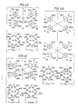
- FIGURE 4A an isometric view is shown of the upper openings A1-A4, the upper X-axis 27, the upper Y-axis 28 and the Z-axis 26 to illustrate the orthogonal relationship of the several axes of the body 24.
- force-sensing means such as a coordinated set of resistance-type strain gauges
- each opening i.e., at the 12 o'clock or the 0-degrees angular position in the opening itself as well as at the 6 o'clock or 180-degrees angular position within these opening
- a first pair of matched gauges 101a and 101b are respectively mounted in the 0-degrees position of the opening A1 and a second matched pair of gauges 101c and 101d are mounted in the 180-degrees position of the same opening A1.
- a first matched pair of gauges 103a and 103b are mounted side-by-side at the top of the opening A3 and a second matched pair of gauges 103c and 103d are mounted side-by-side at the bottom or 180-degrees position of the opening A3.
- another bridge circuit A2-A4 is provided by cooperatively mounting a corresponding set of force-sensing gauges 102a-102d and 104a-104d in the diametrically opposed openings A2 and A4.
- a corresponding set of force-sensing gauges 102a-102d and 104a-104d in the diametrically opposed openings A2 and A4.
- the bridges A1-A3 and A2-A4 are each cooperatively arranged as depicted in FIGURE 4A so that when a bending moment acting on the body 24 produces tension in that side of the body in which the opening A2 is located, the Wheatstone bridge A1-A3 will produce an output signal representative of what will hereafter be characterized as a positive bending moment about the X-axis 27 (i.e., +Moment X-X).
- the bridge circuit Al-A3 will then produce a negative output signal showing that there is a negative bending moment (-Moment X-X) acting on the body.
- the bridge circuit A2-A4 functions to produce a positive output signal (i.e. +Moment Y-Y) when the side of the body 24 containing the opening A1 is in tension and a negative output signal (i.e., -Moment Y-Y) when the opposite side of the body containing the opening A3 is located is in tension.
- a positive output signal i.e. +Moment Y-Y
- a negative output signal i.e., -Moment Y-Y
- FIGURE 4B an isometric view similar to FIGURE 4A is shown, but in this view both the upper openings A1-A4 and the lower openings B1-B4 are depicted.
- the aligned central axes of the upper openings A1 and A3 together define the upper X-axis 27 and the central axes of the lower openings B1 and B3 cooperate to define the lower X-axis 29, with these two X-axes together with the Z-axis cooperatively defining a longitudinal X-Z plane including the X-axes and the Z-axis 26.
- the aligned central axes of the two upper openings A2 and A4 define the upper Y-axis 28 and the axes of the two lower openings B2 and B4 define the lower Y-axis 30, with these upper and lower Y-axes together with the Z-axis 26 respectively defining a longitudinal Y-Z plane perpendicular to the longitudinal X-Z plane defined by the upper and lower X-axes.
- force-sensing means are cooperatively arranged in each of the openings A1-A4 and B1-4 for detecting laterally-directed shear forces acting on the body 24 of the new and improved force-measuring means 20.
- shear forces could be detected with only a single sensor in each of the openings A1-A4 and B1-B4, in the practice of the present invention it is instead preferred to position a single force sensor on each side of each opening.
- the optimum sensitivity is attained by mounting these force sensors so that for any given opening one of the associated sensors is at the 3 o'clock or 90-degrees angular position in the opening and the other associated sensor in that opening is at the 9 o'clock or 270 degrees angular position.
- one leg of the bridge circuit A1-B1 includes the force sensors 201a and 201b in the upper opening A1 and its associated leg is comprised of the force sensors 301a and 301b mounted on opposite sides of the lower opening B1.
- the other leg of the bridge circuit A1-B1 is similarly comprised of the force sensors 203a and 203b mounted within the upper opening A3 and the sensors 303a and 303b that are mounted on opposite sides of the lower opening B3.
- the bridge circuit A1-B1 will, therefore, produce an output signal (i.e., Shear X-X) representative of the lateral shear forces acting in the X-Z plane of the tool body 24.
- the bridge circuit A2-B2 will be effective for measuring the lateral shear forces acting in the Y-Z plane of the body 24 and producing a corresponding output signal (i.e., Shear Y-Y).
- FIGURE 4C an isometric view is shown of the lower openings B1-B4, the lower X-axis 29, the lower Y-axis 30 and the Z-axis 26.
- force-sensing means are mounted in each quadrant of the lower openings B1 and B2.
- these force-sensing means (such as typical strain gauges 401a-401d and 403a-403d) are respectively mounted at the 0-degrees, 90-degrees, 180-degrees and 270-degrees positions within the lower openings B1 and B3.
- additional force-sensing means such as typical strain gauges 402a-402d and 404a-404d, are mounted in each quadrant of the lower openings B2 and B4.
- additional force-sensing means such as typical strain gauges 402a-402d and 404a-404d, are mounted in each quadrant of the lower openings B2 and B4.
- maximum sensitivity is provided by mounting the strain gauges 402a-404d at the 45-degrees, 135-degrees, 225-degrees and 315-degrees positions in the lower opening B2 and by mounting the other strain gauges 404a-404d at the same angular positions in the lower opening B4.
- Measurement of the weight-on-bit is, therefore, obtained by arranging the several strain gauges 401a-401d and 403a-403d in a typical Wheatstone bridge B1-B3 to provide corresponding output signals (i.e., WOB).
- the torque measurements are obtained by connecting the several gauges 402a-402d and 404a-404d into another bridge B2-B4 that produces corresponding output signals (i.e., Torque).
- FIGURES 4A-4C can be mounted in various arrangements on the body 24.
- the several force sensors in the four upper openings A1-A4 and in the lower openings B1-B4 in such a manner that although the force sensors in a given opening are separated from one another, each sensor is located in an optimum position for providing the best possible response. Accordingly, as will be apparent by comparing FIGURES 4A-4C with one another, the several sensors are all positioned so as to not interfere with one another and to maximize the output signals from each sensor.
- the shear sensors 201a and 201b are each mounted at their respective optimum locations in the same openings as are the bending moment sensors 101a-101d. It will, of course, be recognized that the several sensors located in the upper opening A1 are each secured to the body 24 in a typical manner such as with a suitable adhesive.
- the force-measuring means 20 it has also been found advantageous to mount one or more terminal strips, as at 31 and 32, in each of the several openings to facilitate the interconnection of the force sensors in any given opening to one another as well as to provide a convenient terminal that will facilitate connecting the sensors to various conductors, as at 33, leading to the measuring circuitry in the MWD tool 19 (not seen in FIGURE 5).
- the several force sensors be protected from the borehole fluids and the extreme pressures and temperatures normally encountered in boreholes by sealing the sensors within their respective openings A1-A4 and B1-B4 by means of typical fluid-tight closure members (not shown in the drawings).
- the enclosed spaces defined in these openings and their associated interconnecting wire passages are usually filled with a suitable oil that is maintained at an elevated pressure by means such as a piston or other typical pressure-compensating member that is responsive to borehole conditions.
- Standard feed-through connectors (not shown in the drawings) are arranged as needed for interconnecting the conductors in these sealed spaces with their corresponding conductors outside of the oil-filled spaces.
- the accepted practice heretofore for determining whether the earth-boring apparatus is being diverted from its present directional course has been to simply measure the bending moments acting at one or more locations in the lower portion of a drill string and compute the magnitude and direction of any diverting force from these measurements alone. It has, nevertheless, been found that ordinarily there are significant bending moments which, as depicted at Mb in FIGURE 2, are acting upwardly on the earth-boring apparatus; and, as a result, these bending moments Mb must be taken into account for accurately computing the total magnitudes and angular directions of any lateral forces Fb that are tending to divert the earth-boring apparatus from its present course of excavation during a typical drilling operation.
- the tool body 24 of the force-measuring means 20 is coupled at a predetermined location in the drill string 11 above the drill bit 14 so that it can be successively operated to obtain a plurality of independent force measurements at that location at selected time intervals during a drilling operation.
- One group of these force measurements that are made at a given time is used for determining the magnitude and the absolute angular direction of the total bending moment, Mo, that is then acting on the drill string 11 at that location above the drill bit 14.
- Another group of these force measurements is uniquely used for determining the magnitude and the absolute angular direction of the laterally-directed shear force, Fo, acting at the same given time on the drill string 11 at the level of the body 24.
- Fo laterally-directed shear force
- a determination may be made of the magnitude of the corresponding lateral (shear) force, Fb, and the corresponding bending moment, Mb, that is tending to divert the drill bit 14 away from its course of excavation.
- the true direction or heading of the drill bit can be accurately established.
- an analysis of the computed bending moment Mb that is acting on the drill bit 14 will indicate whether the bit is advancing upwardly or downwardly as well as provide at least a general idea of the rate of ascent or descent of the drill bit as it continues to excavate the borehole 15. Accordingly, by periodically obtaining these two groups of independent force measurements during the course of a typical drilling operation with the new and improved apparatus of the invention and utilizing these measurements in accordance with the methods of the invention, the future course of the drill bit 14 can be accurately predicted.
- one group of independent measurements are respectively made along the X and Y orthogonal measurement axes which originate at the Z-axis 26 of the body 24.
- One series of these measurements involves independently measuring the bending moment acting on the body 24 along the longitudinal plane defined by the X-axis 27 and the Z-axis 26 of the body (i.e., Moment X-X as provided by the output signals of the bridge circuit A2-A4).
- Another series of these independent measurements is made to measure the bending moment acting on the body 24 along the Y-Z longitudinal plane of the body (i.e., the output signals Moment Y-Y provided by the bridge circuit A1-A3).
- the overall resultant bending moment Mo acting on the body 24 is determined by computing the square root of the summation of the square of Moment X-X and the square of Moment Y-Y.
- the absolute angular direction of this resultant bending moment Mo is then determined by algebraically dividing the absolute value of the Moment Y-Y by the absolute value of the Moment X-X to compute the trigonometric tangent of the angle between the X-axis and the resultant bending moment Mo.
- the previously mentioned other group of independent strain measurements are obtained for determining the lateral or shear force Fo acting transversely on the body 24.
- the force Fo is uniquely determined by measuring the bending moments acting at longitudinally-spaced upper and lower measuring points on the body 24 and, by means of a bridge circuit formed of these force sensors, combining these force measurements so as to directly measure the differential bending moments between the upper and lower measuring points in each orthogonal axis of the tool body 24. These differential measurements are then uniquely utilized for accurately determining the shear force Fo acting laterally on the body 24.
- one series of these strain measurements is made by simultaneously measuring the forces (i.e., the tension forces or the compression forces) which are acting at longitudinally-spaced upper and lower positions on opposite sides of the body 24 for determining the longitudinal forces acting in the X-Z plane of the body (i.e., the forces measured in the openings A1 and B1 are combined with the forces measured in the diametrically-opposite openings A3 and B3).
- the forces i.e., the tension forces or the compression forces
- Shear Y-Y another series of these measurements (e.g., Shear Y-Y) is made in the upper and lower openings A2 and B2 and in their respective diametrically-opposite openings A4 and B4 to determine the longitudinal forces simultaneously acting in the Y-Z plane of the body 24.
- the strain gauges in any given one of the openings are actually measuring the strain due to the bending moment in that section of the body 24.
- the gauges 201a and 201b mounted on the opposite sides of the upper opening A1 measure the bending moment on that side of the body 24 at the level of the upper openings; and the gauges 301a and 301b mounted on opposite sides of the lower opening B1 that is directly below the opening A1 are simultaneously measuring the bending moments acting at the lower level and on the same side of the body.
- gauges 201a and 201b By cooperatively combining the gauges 201a and 201b with the gauges 301a and 301b as illustrated in FIGURE 4B to comprise two legs on one side of the bridge circuit A1-B1, together these two legs will uniquely cooperate for providing an overall measurement that is representative of the differential of bending moment on that side of the body 24.
- the forces that are being measured at each of the upper and lower openings are quite substantial, if each force is separately measured and these separate measurements are used to compute the overall differential between the forces, even normal deviational errors in the individual measurements would greatly affect the accuracy of any differential that is subsequently computed from those measurements.
- the strain gauges 203a and 203b are similarly mounted in the upper opening A3 and cooperatively connected to the gauges 303a and 303b in the lower opening B3 therebelow as illustrated in FIGURE 4B to form the two legs on the other side of the bridge circuit A1-B1 for directly measuring the differential bending moment on the opposite side of the body between the openings A3 and B3. Accordingly, by combining these eight strain gauges to form the bridge circuit A1-B1 depicted in FIGURE 4B, it will be recognized that the output signals from the bridge circuit (i.e., Shear X-X) will be representative of the overall differential, Mx, between the bending moments acting at longitudinally-spaced locations in the X-Z plane of the body 24.
- Shear X-X the output signals from the bridge circuit
- the transfer function is a mathematical conversion factor which takes into account the elastic characteristics of the one or more bodies coupling the drill bit 14 to the tool body 24.
- the transfer function must therefore be computed for each particular configuration of drill collars, stabilizers, tool bodies, or whatever is included in the drill string that may affect the directional course of the boring apparatus such as the drill bit 14.
- the first thing that must be done in determining the transfer function is to establish a mathematical model of whatever combination of tool bodies and the like that will be used to couple a given earth-boring device such as the drill bit 14 to the tool body 24.
- the mathematical model is utilized to compute four so-called "influence coefficients" C1-C4 as follows:
- the weight (i.e., W as shown in FIGURE 2) of the one or more bodies between the drill bit 14 and the tool body 24 must also be considered whenever the directional drilling tool 10 is not vertical. In other words, whenever the directional drilling tool 10 is vertical, the weight W does not contribute to either the bending moment Mo or the lateral force Fo. On the other hand, if the drilling tool 10 is inclined as depicted in FIGURE 2, the component of the distributed weight W which affects the bending moment Mo and the lateral force Fo is that side of the force triangle that is perpendicular to the longitudinal axis of the tool.
- Equation 9 This transfer function is arbitrarily designated by "H” and Equation 9 is then rewritten as follows: It is, of course the principal object of the present invention to employ the new and improved methods and apparatus as described above for predicting the probable future directional course of the earth-boring apparatus, such as the drillbit 14, that is coupled to the directional tool 10; and, as far as is possible with the particular type of earth-boring apparatus being used, selectively directing the further advancement of the earth-boring apparatus along a desired course of excavation.
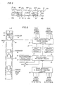
- the MWD tool 19 is preferably arranged as schematically depicted in FIGURE 6.
- the data-transmitting means 22 preferably include an acoustic signaler 34 such as one of those described, for example, in U.S. Patent Nos. 3,309,565 and 3,764,970 which is arranged to transmit either frequency-modulated or phase-encoded data signals to the surface by way the downwardly-flowing mud stream 17.
- the signaler 34 includes a fixed multi-bladed stator 35 that is operatively associated with a rotating multi-bladed stator 35 that is operatively associated with a rotating multi-bladed rotor 36 for producing acoustic signals of the desired character.
- the rotor 36 is rotatably driven by means such as a typical hydraulic motor 37 that is operatively controlled by suitable motor-control circuitry as at 38.
- the data-transmitting means 22 also include a typical turbine-powered hydraulic pump 39 which is driven by the mud stream 17 for supplying the hydraulic fluid to the motor 37 as well as for driving a motor-driven generator 40 that supplies power to the several electrical components of the MWD tool 19.
- the output signals from the WOB bridge circuit B1-B3 and from the Torque bridge circuit B2-B4 are coupled to the data-aquisition and motor-control circuitry 38 for driving the acoustic signaler motor 37 as needed for transmitting data signals to the surface which are representative of those several measurements.
- condition-measuring devices included in the MWD tool 19 may also be coupled to the circuitry 38 for transmitting data signals to the surface which are representative of those measured conditions.
- the position-measuring means 21 of the directional drilling tool 10 must be cooperatively arranged to provide output signals which are representative of the spatial position of the tool in the borehole 15.
- the position-measuring means 21 include means such as a typical tri-axial magnetometer 40 that is cooperatively arranged to provide electrical output signals representative of the angular position of the directional drill tool 10 in relation to a fixed, known reference such as the global magnetic north pole.
- the position-measuring means 21 also include a typical tri-axial accelerometer 41 cooperatively arranged for providing electrical output signals representative of the angle of inclination of the directional drilling tool 10 from the vertical.
- the output signals from the accelerometer 41 could, of course, be used to provide alternative reference signals indicative of the angular position of the tool 10 in relation to a fixed, known reference to true vertical.
- the various sensors which respectively comprise the magnetometer 40 and the accelerometer 41 are cooperatively mounted either as depicted in the previously-mentioned Tanguy patent or in diametrically-opposed enclosed chambers arranged at convenient locations on one of the tool bodies such as the tool body 24.
- the output signals of these position-measuring sensors 40 and 41 are respectively correlated with appropriate reference signals, as at 42 and 43, and combined by typical measurement circuitry, as at 44, to provide input signals to the data-acquisition and motor-control circuitry 44 representative of the azimuthal position and the angle of inclination of the directional drilling tool 10 in the borehole 15.
- the directional drilling tool is cooperatively arranged to provide one set of output signals which are representative of the magnitudes and angular directions of the bending moments and the lateral forces that are acting on the earth-boring apparatus 14 and another set of output signals which are representative of the spatial position of the new and improved tool 10.
- these output signals are transmitted to the surface by the data-signalling means 22 where they are detected and processed by way of typical signal-processing circuitry (not seen in the drawings) to provide suitable indications and records.
- the directional measurements provided by the force-measuring means 20 are related to the X-axes 27 and 29 of the body 24.
- the measurements from the force-measuring means 20 must, of course, be appropriately correlated with the directional measurements of the position-measuring means 21 to determine the true azimuthal orientations of the side force Fb and the bending moment Mb that are acting on the drill bit at any given time.
- the simplest way of correlating these two sets of directional measurements is to assume that the X-axis of the sensors in the accelerometer 41 (or the X-axis of the sensors in the magnetometer 40) is the reference axis for the tool 10 and obtain all of the measurements at the same time so that the only correction that is needed will be to account for the constantly changing angle (i.e., the angle as used in the following Equation 7) that will exist at any given time between the computed angular direction of the force Fb (or the computed angular direction of the bending moment Mb) and the previously-mentioned selected reference axis for the tool 10 (i.e., the X-axis of the sensors for either the magnetometer 40 or the accelerometer 41).
- the constantly changing angle i.e., the angle as used in the following Equation 7
- ⁇ t ⁇ t + ⁇ t + K Eq. 7
- ⁇ t azimuthal orientation of lateral force Fb (or bending moment Mb) at time of measurement t
- ⁇ t azimuthal direction of local X-axis at time of measurement t measured from fixed reference axis of either magnetometer 40 or accelerometer 41
- ⁇ t angular direction of lateral force Fb (or bending moment Mb) at time of measurement t
- K fixed correction angle for angular displacement between X-axes of force sensors in one tool body and magnetometer sensors (or accelerometer sensors) in other tool body after the assembly of those tool bodies into MWD tool 19
- This basic correlation can, of course, be done either by sending the various signals separately to the surface for processing and combining there or in the MWD tool 19 itself by means of suitable downhole circuitry, such as at 45, which has been appropriately arranged to perform the directional computations as well as the previously-discussed computation of the transfer function.
- the several signals are then preferably combined by means of the additional downhole circuitry 44.
- any change in the angle of inclination and azimuthal direction of the tool 10 will ordinarily be gradual, these parameters do not have to be continuously measured.
- two or more piezoelectric accelerometers 46 and 47 are cooperatively mounted in enclosed, air-filled chambers on opposite sides of the body 24 and arranged for providing output signals representative of the rotational acceleration, , of the tool 10 during the drilling operation.
- the operator will be able to determine with reasonable accuracy the azimuthal direction in which the drill bit 14 is then proceeding as well as to predict its probable future directional course.
- the measurements of the bending moment acting on the drill bit 14 at any given moment are also of major significance since they are directly related to the character of the formation materials that are being penetrated at any given time by the bit.
- the bit 14 will be uniformly cutting away the formation materials in every sector of the bottom of the borehole 15.
- the materials in one sector of the bottom surface of the borehole 15 be softer than the materials in the other sectors there will be a corresponding tendency for the bit 14 to cut away these softer materials faster than the harder materials in the other sectors. This unbalanced upward force on the bit 14 is, of course, a significant source of the bending moment Mb on the bit.
- the bending moment Mb on the bit 14 produces a corresponding deflection of the bit in relation to its longitudinal axis.
- the bending moment Mb on the bit 14 tends to tilt it out of axial alignment with the central axis of the tool 10 and the drill string 11.
- the tilting of the bit 14 is proportionally representative of the rate at which the bit is presently moving above or below a straight-line projection of the longitudinal axis of the tool 10. Accordingly, if there is little or no bending moment Mb acting on the bit 14, it will generally continue drilling along a course of excavation which is the straight-line extension of the Z-axis or longitudinal axis of the tool 10 and the drill string 11.
- Equation 9 is dependent on the nature of the formation being penetrated. This obviously represents an unknown parameter that must be determined if the radius of curvature of the drill bit 14 is to be computed.
- typical prediction corrector techniques are employed to compute the radius R. For example, if the formation characteristic ⁇ for those formations that are then being drilled is arbitrarily assumed to have a value of 1, the corresponding radius can then be computed. Then, by making a series of successive directional measurements as that interval is being drilled, the actual radius R of that particular interval of the borehole 15 can be calculated. Using this actual radius R, Equation 9 can be solved for ⁇ to arrive at a better value for the actual formation characteristic in this particular borehole interval.
- This later value of ⁇ is, of course, used for computing R so as to arrive at a prediction of the radius of the borehole interval that will be drilled if no further changes are made in the course of the drill bit 14. It will, of course, be understood that the values of the formation characteristic ⁇ will change as different types of formation materials are encountered so that there must be a continuous comparison of the predicted value of the radius R and the actual radius R as verified by the directional measurements of the new and improved directional tool 10. This iterative technique must be continuously used to verify the accuracy of the predicted course and radius of the borehole intervals that are yet to be drilled.
- the various measurements described above can be used to control the course of excavation of any standard earth-boring apparatus such as the drill bit 14. Accordingly, as previously mentioned, when an ordinary drill bit is being used the operator can selectively change various drilling parameters and use the several measurements provided by the new and improved drilling tool 10 to achieve at least a minimal control of the direction of the course of excavation of the drill bit 14. Since the new and improved measurements of the directional drilling tool 10 will enable the operator to know when the drill bit 14 is starting to move away from a desired course of excavation, even such minimal controls will often suffice to allow the operator to return the drill bit to the desired course before it has strayed too far.
- the directional drilling tool 10 of the present invention can also be used with both a big-eye bit and a bent-sub directional tool.
- the drilling operation would proceed with the new and improved directional drilling tool 10 providing the several directional measurements described above.
- the big-eye bit or the bent sub tool are operated in their customary manner to initiate a change in the direction of the borehole being drilled.
- the new and improved methods of the present invention can be effectively utilized as needed to achieve the directional change by either the big-eye bit or the bent-sub tool.
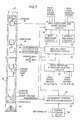
- the directional drilling tool 10 ⁇ shown in FIGURE 7 is identical to the tool 10 already described by reference to FIGURE 6 except that the flow of drilling mud into the drill bit 50 is controlled by means of a rotatable fluid diverter 51 that is selectively driven by a diverter motor 52 cooperatively arranged to rotate in either rotational direction and at various rotational speeds as needed to regulate the flow of mud through the respective mud ports of the drill bit 50.
- a typical rotary position transducer 53 is operatively arranged on the shaft connecting the diverter to the motor for providing output signals that are representative of the rotational speed of the diverter 51 as well as its angular position in relation to the alternative tool 10 ⁇ .
- feedback signals from the transducer 53 are fed to appropriate summing-and-integrating circuits 54.
- the output signals from the transducer 53 are also coupled to the data-acquisition and motor-control circuitry 38 to provide output signals at the surface representative of the rotational speed and the angular position of the diverter 51 relative to the body of the tool 10 ⁇ .
- a reference signal source as at 55, is cooperatively arranged to be selectively coupled to the servo driver 52 by means such as by a typical control device 56 mounted in the tool 10 ⁇ and adapted to be operated in response to changes in some selected downhole condition which can be readily varied or controlled from the surface.
- the control device 56 could be chosen to be responsive to a predetermined change in the flow rate of the drilling mud in the drill string 11.
- the directional control tool 10 ⁇ could be readily changed from one operational mode to another desired mode by simply controlling the mud pumps (not depicted) as required to momentarily increase or decrease the flow rate of the drilling mud which is then circulating in the drill string 11 to some predetermined higher or lower flow rate.
- the control device 56 could just as well be chosen to be actuated in response to predetermined levels or variations in the aforementioned weight-on-bit measurements in the drill string 11.
- an alternative remotely-actuated device 56 could be responsive to the passage of slugs of various radioactive tracer fluids in the drilling mud stream. Other means for selectively actuating the control device 56 will be apparent to those skilled in the art.
- the directional drilling tool 10 ⁇ is operated so that the motor 52 will selectively rotate the fluid diverter 51 as needed to accomplish any desired changes in the course of excavation of the drill bit 50 or to maintain it in a selected course of excavation. It will, of course, be appreciated that the continued diversion of the drill bit 50 in a selected lateral direction will progressively excavate the borehole 15 along an extended, somewhat-arcuate course. It is, however, not always feasible nor necessary to continue deviation of a given borehole as at 15.
- the directional tool 10 ⁇ is further arranged so that further diversion of the bit 50 can be selectively discontinued so that the bit will thereafter advance along a generally straight-line course of excavation.
- the remotely-actuated control device 56 is actuated (such as, for example, by momentarily changing the speed of the mud pumps at the surface) to cause the motor 52 to function to control the diverter 51 as needed to change the directional course of the bit 50. It will be recognized, therefore, by a review of the aforementioned Leising application that the new and improved tool 10 ⁇ can be controlled as needed to selectively direct the drill bit 50 along a selected course of excavation.
- the present invention has provided new and improved methods and apparatus for guiding well-boring apparatus of different designs along selected courses of excavation.
- well-boring apparatus coupled thereto can be reliably advanced in any selected azimuthal course and at any selected inclination without removing the drill string or using special apparatus to effect a minor course correction.
Landscapes
- Life Sciences & Earth Sciences (AREA)
- Engineering & Computer Science (AREA)
- Geology (AREA)
- Mining & Mineral Resources (AREA)
- Physics & Mathematics (AREA)
- Environmental & Geological Engineering (AREA)
- Fluid Mechanics (AREA)
- General Life Sciences & Earth Sciences (AREA)
- Geochemistry & Mineralogy (AREA)
- Geophysics (AREA)
- Force Measurement Appropriate To Specific Purposes (AREA)
- Earth Drilling (AREA)
Applications Claiming Priority (2)
| Application Number | Priority Date | Filing Date | Title |
|---|---|---|---|
| US06/896,891 US4739841A (en) | 1986-08-15 | 1986-08-15 | Methods and apparatus for controlled directional drilling of boreholes |
| US896891 | 1986-08-15 |
Publications (3)
| Publication Number | Publication Date |
|---|---|
| EP0256796A2 true EP0256796A2 (de) | 1988-02-24 |
| EP0256796A3 EP0256796A3 (en) | 1988-09-21 |
| EP0256796B1 EP0256796B1 (de) | 1991-04-03 |
Family
ID=25407022
Family Applications (1)
| Application Number | Title | Priority Date | Filing Date |
|---|---|---|---|
| EP87306999A Expired - Lifetime EP0256796B1 (de) | 1986-08-15 | 1987-08-07 | Verfahren und Vorrichtung zum gesteuerten Richtbohren von Bohrungen |
Country Status (5)
| Country | Link |
|---|---|
| US (1) | US4739841A (de) |
| EP (1) | EP0256796B1 (de) |
| CA (1) | CA1311372C (de) |
| DE (1) | DE3769033D1 (de) |
| NO (1) | NO873214L (de) |
Cited By (4)
| Publication number | Priority date | Publication date | Assignee | Title |
|---|---|---|---|---|
| EP0640743A3 (de) * | 1993-08-31 | 1995-09-27 | Anadrill Int Sa | Kraftmessdose zur Erfassung des, von auf den Bohrmeissel während des bohrens ausgeübten, Gewichts und Drehmoments. |
| WO1995026454A3 (en) * | 1994-03-25 | 1995-11-30 | Amoco Corp | Curved drilling apparatus |
| US6467557B1 (en) | 1998-12-18 | 2002-10-22 | Western Well Tool, Inc. | Long reach rotary drilling assembly |
| US6470974B1 (en) | 1999-04-14 | 2002-10-29 | Western Well Tool, Inc. | Three-dimensional steering tool for controlled downhole extended-reach directional drilling |
Families Citing this family (48)
| Publication number | Priority date | Publication date | Assignee | Title |
|---|---|---|---|---|
| US4905773A (en) * | 1987-11-02 | 1990-03-06 | Underground Technologies | Self-propelled subsoil penetrating tool system |
| US4979112A (en) * | 1988-05-11 | 1990-12-18 | Baker Hughes Incorporated | Method and apparatus for acoustic measurement of mud flow downhole |
| US4901806A (en) * | 1988-07-22 | 1990-02-20 | Drilex Systems, Inc. | Apparatus for controlled absorption of axial and torsional forces in a well string |
| US4909336A (en) * | 1988-09-29 | 1990-03-20 | Applied Navigation Devices | Drill steering in high magnetic interference areas |
| US5181172A (en) * | 1989-11-14 | 1993-01-19 | Teleco Oilfield Services Inc. | Method for predicting drillstring sticking |
| US5220963A (en) * | 1989-12-22 | 1993-06-22 | Patton Consulting, Inc. | System for controlled drilling of boreholes along planned profile |
| US5419405A (en) * | 1989-12-22 | 1995-05-30 | Patton Consulting | System for controlled drilling of boreholes along planned profile |
| US5133418A (en) * | 1991-01-28 | 1992-07-28 | Lag Steering Systems | Directional drilling system with eccentric mounted motor and biaxial sensor and method |
| US5226488A (en) * | 1991-07-10 | 1993-07-13 | Bor-Mor Inc. | Truck mounted boring system |
| US5339913A (en) * | 1991-10-09 | 1994-08-23 | Rives Allen K | Well orienting tool and method of use |
| WO1993012318A1 (en) * | 1991-12-09 | 1993-06-24 | Patton Bob J | System for controlled drilling of boreholes along planned profile |
| WO1993012319A1 (en) * | 1991-12-09 | 1993-06-24 | Patton Bob J | System for controlled drilling of boreholes along planned profile |
| US5720355A (en) * | 1993-07-20 | 1998-02-24 | Baroid Technology, Inc. | Drill bit instrumentation and method for controlling drilling or core-drilling |
| BE1007274A5 (fr) * | 1993-07-20 | 1995-05-09 | Baroid Technology Inc | Procede de commande de la tete d'un dispositif de forage ou de carottage et installation pour la mise en oeuvre de ce procede. |
| US5456141A (en) * | 1993-11-12 | 1995-10-10 | Ho; Hwa-Shan | Method and system of trajectory prediction and control using PDC bits |
| US5988243A (en) * | 1997-07-24 | 1999-11-23 | Black & Decker Inc. | Portable work bench |
| NL1015365C1 (nl) * | 1999-07-02 | 2001-01-03 | Heerema Ondergrondse Infrastru | Jetgraafinrichting. |
| US6315062B1 (en) | 1999-09-24 | 2001-11-13 | Vermeer Manufacturing Company | Horizontal directional drilling machine employing inertial navigation control system and method |
| US6308787B1 (en) | 1999-09-24 | 2001-10-30 | Vermeer Manufacturing Company | Real-time control system and method for controlling an underground boring machine |
| GB2371625B (en) * | 2000-09-29 | 2003-09-10 | Baker Hughes Inc | Method and apparatus for prediction control in drilling dynamics using neural network |
| WO2002035048A1 (en) | 2000-10-27 | 2002-05-02 | Vermeer Manufacturing Company | Solid-state inertial navigation control system for a horizontal drilling machine |
| US6547016B2 (en) * | 2000-12-12 | 2003-04-15 | Aps Technology, Inc. | Apparatus for measuring weight and torque on drill bit operating in a well |
| US6523623B1 (en) * | 2001-05-30 | 2003-02-25 | Validus International Company, Llc | Method and apparatus for determining drilling paths to directional targets |
| GB2417792B (en) * | 2003-03-31 | 2007-05-09 | Baker Hughes Inc | Real-time drilling optimization based on mwd dynamic measurements |
| US20050103123A1 (en) * | 2003-11-14 | 2005-05-19 | Newman Kenneth R. | Tubular monitor systems and methods |
| US7775099B2 (en) * | 2003-11-20 | 2010-08-17 | Schlumberger Technology Corporation | Downhole tool sensor system and method |
| EP1709293B1 (de) * | 2003-12-19 | 2007-11-21 | Baker Hughes Incorporated | Verfahren und vorrichtung zur verbesserung der richtungsgenauigkeit und -steuerung unter verwendung von grundbohrungsanordnungsbiegemessungen |
| WO2005066452A1 (en) * | 2003-12-29 | 2005-07-21 | Noble Drilling Services, Inc. | Turbine generator system and method |
| US7730967B2 (en) * | 2004-06-22 | 2010-06-08 | Baker Hughes Incorporated | Drilling wellbores with optimal physical drill string conditions |
| US7866413B2 (en) * | 2006-04-14 | 2011-01-11 | Baker Hughes Incorporated | Methods for designing and fabricating earth-boring rotary drill bits having predictable walk characteristics and drill bits configured to exhibit predicted walk characteristics |
| WO2007137208A2 (en) * | 2006-05-19 | 2007-11-29 | Neoguide Systems, Inc. | Methods and apparatus for displaying three-dimensional orientation of a steerable distal tip of an endoscope |
| WO2008101285A1 (en) * | 2007-02-20 | 2008-08-28 | Commonwealth Scientific & Industrial Research Organisation | Method and apparatus for modelling the interaction of a drill bit with the earth formation |
| US8286729B2 (en) * | 2008-02-15 | 2012-10-16 | Baker Hughes Incorporated | Real time misalignment correction of inclination and azimuth measurements |
| US8525690B2 (en) * | 2009-02-20 | 2013-09-03 | Aps Technology, Inc. | Synchronized telemetry from a rotating element |
| US8397562B2 (en) * | 2009-07-30 | 2013-03-19 | Aps Technology, Inc. | Apparatus for measuring bending on a drill bit operating in a well |
| US8919457B2 (en) | 2010-04-30 | 2014-12-30 | Mark Hutchinson | Apparatus and method for determining axial forces on a drill string during underground drilling |
| US9272337B2 (en) * | 2012-08-17 | 2016-03-01 | Baker Hughes Incorporated | System and method for forming a bore in a workpiece |
| US9371693B2 (en) | 2012-08-23 | 2016-06-21 | Ramax, Llc | Drill with remotely controlled operating modes and system and method for providing the same |
| US10094172B2 (en) | 2012-08-23 | 2018-10-09 | Ramax, Llc | Drill with remotely controlled operating modes and system and method for providing the same |
| WO2015117151A2 (en) | 2014-02-03 | 2015-08-06 | Aps Technology, Inc. | System, apparatus and method for guiding a drill bit based on forces applied to a drill bit |
| US9927310B2 (en) | 2014-02-03 | 2018-03-27 | Aps Technology, Inc. | Strain sensor assembly |
| WO2015122918A1 (en) | 2014-02-14 | 2015-08-20 | Halliburton Energy Services Inc. | Drilling shaft deflection device |
| US10161196B2 (en) | 2014-02-14 | 2018-12-25 | Halliburton Energy Services, Inc. | Individually variably configurable drag members in an anti-rotation device |
| EP3074589B1 (de) | 2014-02-14 | 2020-03-04 | Halliburton Energy Services, Inc. | Gleichmässig variabel konfigurierbare widerstandselemente in einer drehverhinderungsvorrichtung |
| WO2016043752A1 (en) | 2014-09-18 | 2016-03-24 | Halliburton Energy Services, Inc. | Releasable locking mechanism for locking a housing to a drilling shaft of a rotary drilling system |
| AU2014412066B2 (en) * | 2014-11-19 | 2018-10-18 | Halliburton Energy Services, Inc. | Drilling direction correction of a steerable subterranean drill in view of a detected formation tendency |
| US11732570B2 (en) * | 2019-07-31 | 2023-08-22 | Schlumberger Technology Corporation | Indirect detection of bending of a collar |
| CN113464050B (zh) * | 2021-06-24 | 2023-08-08 | 成都理工大学 | 一种面向智慧矿山的瓦斯钻孔方法及其机器人系统 |
Family Cites Families (10)
| Publication number | Priority date | Publication date | Assignee | Title |
|---|---|---|---|---|
| US2930137A (en) * | 1954-08-04 | 1960-03-29 | Jan J Arps | Earth borehole crookedness detection and indication |
| US3855857A (en) * | 1973-05-09 | 1974-12-24 | Schlumberger Technology Corp | Force-measuring apparatus for use in a well bore pipe string |
| US4445578A (en) * | 1979-02-28 | 1984-05-01 | Standard Oil Company (Indiana) | System for measuring downhole drilling forces |
| CA1134257A (en) * | 1979-02-28 | 1982-10-26 | Keith K. Millheim | System for measuring downhole drilling forces |
| US4303994A (en) * | 1979-04-12 | 1981-12-01 | Schlumberger Technology Corporation | System and method for monitoring drill string characteristics during drilling |
| US4479564A (en) * | 1979-04-12 | 1984-10-30 | Schlumberger Technology Corporation | System and method for monitoring drill string characteristics during drilling |
| US4324297A (en) * | 1980-07-03 | 1982-04-13 | Shell Oil Company | Steering drill string |
| US4359898A (en) * | 1980-12-09 | 1982-11-23 | Schlumberger Technology Corporation | Weight-on-bit and torque measuring apparatus |
| US4384483A (en) * | 1981-08-11 | 1983-05-24 | Mobil Oil Corporation | Preventing buckling in drill string |
| US4662458A (en) * | 1985-10-23 | 1987-05-05 | Nl Industries, Inc. | Method and apparatus for bottom hole measurement |
-
1986
- 1986-08-15 US US06/896,891 patent/US4739841A/en not_active Expired - Lifetime
-
1987
- 1987-07-31 NO NO873214A patent/NO873214L/no unknown
- 1987-08-07 DE DE8787306999T patent/DE3769033D1/de not_active Expired - Fee Related
- 1987-08-07 EP EP87306999A patent/EP0256796B1/de not_active Expired - Lifetime
- 1987-08-14 CA CA000544545A patent/CA1311372C/en not_active Expired - Lifetime
Cited By (5)
| Publication number | Priority date | Publication date | Assignee | Title |
|---|---|---|---|---|
| EP0640743A3 (de) * | 1993-08-31 | 1995-09-27 | Anadrill Int Sa | Kraftmessdose zur Erfassung des, von auf den Bohrmeissel während des bohrens ausgeübten, Gewichts und Drehmoments. |
| WO1995026454A3 (en) * | 1994-03-25 | 1995-11-30 | Amoco Corp | Curved drilling apparatus |
| US6467557B1 (en) | 1998-12-18 | 2002-10-22 | Western Well Tool, Inc. | Long reach rotary drilling assembly |
| US6470974B1 (en) | 1999-04-14 | 2002-10-29 | Western Well Tool, Inc. | Three-dimensional steering tool for controlled downhole extended-reach directional drilling |
| US6708783B2 (en) | 1999-04-14 | 2004-03-23 | Western Well Tool, Inc. | Three-dimensional steering tool for controlled downhole extended-reach directional drilling |
Also Published As
| Publication number | Publication date |
|---|---|
| EP0256796B1 (de) | 1991-04-03 |
| US4739841A (en) | 1988-04-26 |
| CA1311372C (en) | 1992-12-15 |
| NO873214L (no) | 1988-02-16 |
| EP0256796A3 (en) | 1988-09-21 |
| NO873214D0 (no) | 1987-07-31 |
| DE3769033D1 (de) | 1991-05-08 |
Similar Documents
| Publication | Publication Date | Title |
|---|---|---|
| EP0256796B1 (de) | Verfahren und Vorrichtung zum gesteuerten Richtbohren von Bohrungen | |
| EP0263644B1 (de) | Verfahren zur Untersuchung des Widerstandes und des Drehmomentverlustes beim Bohren | |
| US4662458A (en) | Method and apparatus for bottom hole measurement | |
| CA2550405C (en) | Method and apparatus for enhancing directional accuracy and control using bottomhole assembly bending measurements | |
| US4445578A (en) | System for measuring downhole drilling forces | |
| US6438495B1 (en) | Method for predicting the directional tendency of a drilling assembly in real-time | |
| US8397562B2 (en) | Apparatus for measuring bending on a drill bit operating in a well | |
| US8286729B2 (en) | Real time misalignment correction of inclination and azimuth measurements | |
| US11299975B2 (en) | At-bit sensing of rock lithology | |
| EP2553204B1 (de) | Biegung einer welle eines lenkbaren bohrwerkzeuges für bohrlöcher | |
| US10450854B2 (en) | Methods and apparatus for monitoring wellbore tortuosity | |
| EP3504395B1 (de) | Flexible manschette für ein rotierendes lenkbares system | |
| CA1134257A (en) | System for measuring downhole drilling forces | |
| GB2384567A (en) | Filtering of Data for Tendency Control of a Drillstring | |
| Inglis | Current and Future Developments |
Legal Events
| Date | Code | Title | Description |
|---|---|---|---|
| PUAI | Public reference made under article 153(3) epc to a published international application that has entered the european phase |
Free format text: ORIGINAL CODE: 0009012 |
|
| AK | Designated contracting states |
Kind code of ref document: A2 Designated state(s): DE FR GB IT NL |
|
| PUAL | Search report despatched |
Free format text: ORIGINAL CODE: 0009013 |
|
| AK | Designated contracting states |
Kind code of ref document: A3 Designated state(s): DE FR GB IT NL |
|
| 17P | Request for examination filed |
Effective date: 19881018 |
|
| 17Q | First examination report despatched |
Effective date: 19891016 |
|
| RAP1 | Party data changed (applicant data changed or rights of an application transferred) |
Owner name: ANADRILL INTERNATIONAL SA |
|
| GRAA | (expected) grant |
Free format text: ORIGINAL CODE: 0009210 |
|
| ITF | It: translation for a ep patent filed | ||
| AK | Designated contracting states |
Kind code of ref document: B1 Designated state(s): DE FR GB IT NL |
|
| REF | Corresponds to: |
Ref document number: 3769033 Country of ref document: DE Date of ref document: 19910508 |
|
| ET | Fr: translation filed | ||
| PLBE | No opposition filed within time limit |
Free format text: ORIGINAL CODE: 0009261 |
|
| STAA | Information on the status of an ep patent application or granted ep patent |
Free format text: STATUS: NO OPPOSITION FILED WITHIN TIME LIMIT |
|
| 26N | No opposition filed | ||
| PGFP | Annual fee paid to national office [announced via postgrant information from national office to epo] |
Ref country code: GB Payment date: 19920602 Year of fee payment: 6 |
|
| PGFP | Annual fee paid to national office [announced via postgrant information from national office to epo] |
Ref country code: FR Payment date: 19920615 Year of fee payment: 6 |
|
| PGFP | Annual fee paid to national office [announced via postgrant information from national office to epo] |
Ref country code: NL Payment date: 19920831 Year of fee payment: 6 |
|
| PGFP | Annual fee paid to national office [announced via postgrant information from national office to epo] |
Ref country code: DE Payment date: 19920930 Year of fee payment: 6 |
|
| PG25 | Lapsed in a contracting state [announced via postgrant information from national office to epo] |
Ref country code: GB Effective date: 19930807 |
|
| PG25 | Lapsed in a contracting state [announced via postgrant information from national office to epo] |
Ref country code: NL Effective date: 19940301 |
|
| GBPC | Gb: european patent ceased through non-payment of renewal fee |
Effective date: 19930807 |
|
| NLV4 | Nl: lapsed or anulled due to non-payment of the annual fee | ||
| PG25 | Lapsed in a contracting state [announced via postgrant information from national office to epo] |
Ref country code: FR Effective date: 19940429 |
|
| PG25 | Lapsed in a contracting state [announced via postgrant information from national office to epo] |
Ref country code: DE Effective date: 19940503 |
|
| REG | Reference to a national code |
Ref country code: FR Ref legal event code: ST |
|
| PG25 | Lapsed in a contracting state [announced via postgrant information from national office to epo] |
Ref country code: IT Free format text: LAPSE BECAUSE OF NON-PAYMENT OF DUE FEES;WARNING: LAPSES OF ITALIAN PATENTS WITH EFFECTIVE DATE BEFORE 2007 MAY HAVE OCCURRED AT ANY TIME BEFORE 2007. THE CORRECT EFFECTIVE DATE MAY BE DIFFERENT FROM THE ONE RECORDED. Effective date: 20050807 |