EP0256744A1 - Maintenance of a desired pedestrian speed - Google Patents
Maintenance of a desired pedestrian speed Download PDFInfo
- Publication number
- EP0256744A1 EP0256744A1 EP87306878A EP87306878A EP0256744A1 EP 0256744 A1 EP0256744 A1 EP 0256744A1 EP 87306878 A EP87306878 A EP 87306878A EP 87306878 A EP87306878 A EP 87306878A EP 0256744 A1 EP0256744 A1 EP 0256744A1
- Authority
- EP
- European Patent Office
- Prior art keywords
- equipment
- pedestrian
- speed
- output frequency
- maintenance
- Prior art date
- Legal status (The legal status is an assumption and is not a legal conclusion. Google has not performed a legal analysis and makes no representation as to the accuracy of the status listed.)
- Withdrawn
Links
- 238000012423 maintenance Methods 0.000 title claims abstract description 5
- 238000005507 spraying Methods 0.000 claims abstract description 7
- 239000012530 fluid Substances 0.000 claims description 9
- 238000009987 spinning Methods 0.000 claims description 2
- 239000007921 spray Substances 0.000 claims 1
- 239000004009 herbicide Substances 0.000 abstract description 5
- 230000002363 herbicidal effect Effects 0.000 abstract description 4
- 239000000463 material Substances 0.000 description 3
- 238000010586 diagram Methods 0.000 description 1
- 230000000694 effects Effects 0.000 description 1
- 239000007788 liquid Substances 0.000 description 1
- 238000000034 method Methods 0.000 description 1
Images

Classifications
-
- B—PERFORMING OPERATIONS; TRANSPORTING
- B05—SPRAYING OR ATOMISING IN GENERAL; APPLYING FLUENT MATERIALS TO SURFACES, IN GENERAL
- B05B—SPRAYING APPARATUS; ATOMISING APPARATUS; NOZZLES
- B05B9/00—Spraying apparatus for discharge of liquids or other fluent material, without essentially mixing with gas or vapour
- B05B9/03—Spraying apparatus for discharge of liquids or other fluent material, without essentially mixing with gas or vapour characterised by means for supplying liquid or other fluent material
- B05B9/04—Spraying apparatus for discharge of liquids or other fluent material, without essentially mixing with gas or vapour characterised by means for supplying liquid or other fluent material with pressurised or compressible container; with pump
- B05B9/08—Apparatus to be carried on or by a person, e.g. of knapsack type
-
- A—HUMAN NECESSITIES
- A01—AGRICULTURE; FORESTRY; ANIMAL HUSBANDRY; HUNTING; TRAPPING; FISHING
- A01M—CATCHING, TRAPPING OR SCARING OF ANIMALS; APPARATUS FOR THE DESTRUCTION OF NOXIOUS ANIMALS OR NOXIOUS PLANTS
- A01M7/00—Special adaptations or arrangements of liquid-spraying apparatus for purposes covered by this subclass
- A01M7/0089—Regulating or controlling systems
-
- B—PERFORMING OPERATIONS; TRANSPORTING
- B05—SPRAYING OR ATOMISING IN GENERAL; APPLYING FLUENT MATERIALS TO SURFACES, IN GENERAL
- B05B—SPRAYING APPARATUS; ATOMISING APPARATUS; NOZZLES
- B05B12/00—Arrangements for controlling delivery; Arrangements for controlling the spray area
- B05B12/08—Arrangements for controlling delivery; Arrangements for controlling the spray area responsive to condition of liquid or other fluent material to be discharged, of ambient medium or of target ; responsive to condition of spray devices or of supply means, e.g. pipes, pumps or their drive means
- B05B12/12—Arrangements for controlling delivery; Arrangements for controlling the spray area responsive to condition of liquid or other fluent material to be discharged, of ambient medium or of target ; responsive to condition of spray devices or of supply means, e.g. pipes, pumps or their drive means responsive to conditions of ambient medium or target, e.g. humidity, temperature position or movement of the target relative to the spray apparatus
- B05B12/126—Arrangements for controlling delivery; Arrangements for controlling the spray area responsive to condition of liquid or other fluent material to be discharged, of ambient medium or of target ; responsive to condition of spray devices or of supply means, e.g. pipes, pumps or their drive means responsive to conditions of ambient medium or target, e.g. humidity, temperature position or movement of the target relative to the spray apparatus responsive to target velocity, e.g. to relative velocity between spray apparatus and target
Definitions
- This invention relates to maintenance of a desired speed by a pedestrian.
- European patent publication EP-A-0143588 discloses a liquid spraying device which has a control unit, the control unit indicating when the sensed speed of the device is greater than, or less than, an input desired speed.
- this control unit is suitable only for use with wheeled spraying devices and, moreover, relies upon being able to measure accurately the speed of a wheeled vehicle across uneven and overgrown terrain of the type to which it is often necessary to apply a herbicide.
- pedestrian operated plant treatment equipment comprising a device for use in assisting the maintenance of a desired pedestrian speed, the device comprising means for emitting an audible output signal at an output frequency to serve as a guide for maintaining a desired striding rate.
- the signal comprises a regular series of audible pulses, the frequency of which corresponds to the striding rate to be maintained.
- the pulses may be admitted at a higher frequency, with a stride being completed on, for example, every fourth pulse.
- the equipment may advantageously be adapted for delivering herbicide at a controlled flow rate.
- the device may be mounted internally in the plant treatment equipment. Alternatively, the device may be mounted externally, perhaps in a releasable manner. Where the equipment is provided with a battery having an electrical connector for connection to a mains supply to recharge the battery, the device may be fitted to the equipment by engaging it with the electrical connector.
- the device may have its own source of current, but alternatively it may be adapted to draw current from the battery of the spraying equipment.
- the frequency of the signal is preferably adjustable. Such adjustment may be provided not only in order to enable the pedestrian to maintain different speeds, but also to adapt the signal to the actual length of each stride taken by the pedestrian. Thus, if a desired speed is to be maintained, the frequency of the signal will need to be higher for a person who takes relatively short strides than it would need to be for a person who takes relatively long strides.
- One method of calibrating the device is for the pedestrian to walk over a predetermined distance, for example 20 metres, and to count the number of steps taken. The number of steps taken can be used to derive a calibration factor which can be set on the device to obtain a signal of the desired frequency.
- the device may comprise a control member such as a multi-position switch, which is operable to alter the frequency of the signal.
- a control member such as a multi-position switch, which is operable to alter the frequency of the signal.
- each output of the switch may be connected to a signal generator through a respective resistor or combination of resistors.
- the resistors may be chosen, for example, to give signals corresponding to walking speeds of 2.4km/h(1.5mph), 3.2km/h(2.0 mph), 4.0 km/h(2.5mph) and 4.8km/h(3.0mph), assuming a predetermined length of stride.
- the multi-position switch could have a further output connected to a variable resistor which can be adjusted to give any desired walking speed with any length of stride.
- the variable resistors corresponding to the fixed speeds may then be replaced by resistors having appropriate fixed values.
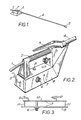
- Figure 1 shows equipment for distributing a fluid over an area of land, to which the fluid is supplied via an inlet duct 1.
- the equipment is adapted to be held by a pedestrian operator, and includes a handset for this purpose, incorporating a handle 2.
- the handle is provided with means for controlling the rate of flow of fluid, such that when the upper part 3 of the handle is squeezed against the remainder of the body of the handle, fluid is allowed to flow along a duct 4 towards a fluid distributing head 5, which is provided with a spinning disc which causes the fluid to be evenly distributed over an area of land.
- the handle 2 is provided with electric leads 5 for connection to a power source, and has a rotary switch 6, a jack socket 7, and an externally mounted sounder 8 provided on the body thereof.
- Figure 3 is a sectional view of a side surface 9 of the handle 2, showing an electronic circuit board 10 mounted to the inner surface thereof by pins 11.
- the circuit board has electrical connections 5, 12 to the power source and to the sounder 8 respectively.
- the electrical power source which may conveniently be a battery, may be accommodated in the handset, or may be carried by a pedestrian operator of the equipment in a back-pack which also contains the fluid which is to be distributed.
- FIG 4 shows the electronic circuitry which may be mounted to the circuit board 10.
- the switch 6 is a BCD type, which is used to set the desired pedestrian speed.
- the switch 6 has a common contact 13 and four other contacts 14, 15, 16, 17.
- the set position of the switch 6 controls the input voltage which is passed to the intergrated circuit IC1, which is a CMOS 556 timer, one section of which is configured as an audio oscillator.
- IC1 which is a CMOS 556 timer, one section of which is configured as an audio oscillator.
- the circuitry has connections 18, 19 for a remotely located piezo sounder, and a jack socket 7, which may be used to supply the audible output tone to, for example, a set of headphones which may be worn by the operator of the equipment.
- the common contact 13 In the embodiment of the invention illustrated in Figure 4, four output frequencies are available.
- the common contact 13 In the first position, the common contact 13 is connected to the first contact 14; in the second postion, the common contact 13 is connected to the second contact 15; in the third position, the common contact 13 is connected to both the first contact 14 and second contact 15; and in the fourth position, the common contact 13 is connected to the third contact 16.
- the power supply When the common contact 13 is connected to the fourth contact 17, the power supply is open circuit, and thus the timer intergrated circuit IC1 is disabled, although the power supply is not disconnected. As the integrated circuit draws minimal power when not connected, it is not necessary to provide a further power switch.
- Changing the position of the switch causes the input voltage to the integrated circuit IC1 to be varied, and hence results in a change of the output frequency of the audible signal.
- the four available output positions correspond to pedestrian speeds of 2.4km/h(1.5 mph), 3.2km/h(2.0 mph), 4.0km/h(2.5 mph) and 4.8km/h(3.0 mph).
- a constant stride length of 0.76m (30 inches) is assumed, and so the four switch positions correspond to output frequencies of 0.88Hz, 1.17Hz, 1.46Hz and 1.76Hz respectively.
- the equipment may include means for providing an indication of travel speed.
- Such means may be operated from one of the wheels, for example in the manner disclosed in British Patent Application No. 8407163 (Publication No. 2,157,025A).
- Speed indication may be provided by a needle moving over a scale. The operator would then walk at a speed which keeps the needle in the appropriate position on the scale. Once this position is reached, the operator could adjust the signal generating device so that the frequency of the signal is coordinated to the strides taken by the operator. Thenceforth, the signal would aid the operator in maintaining the desired speed without the need for him to look constantly at the needle.
Landscapes
- Life Sciences & Earth Sciences (AREA)
- Engineering & Computer Science (AREA)
- Insects & Arthropods (AREA)
- Pest Control & Pesticides (AREA)
- Wood Science & Technology (AREA)
- Zoology (AREA)
- Environmental Sciences (AREA)
- Catching Or Destruction (AREA)
- Nozzles (AREA)
Abstract
Description
- This invention relates to maintenance of a desired speed by a pedestrian.
- It is known, for example from British Patent No. 2131327 and British Patent Application No. 8407163 (Publication No. 2,157,025A), to apply materials such as herbicides by means of equipment which is either carried by a pedestrian, or moved over the ground under the control of the pedestrian. The flow rate of the herbicide is carefully controlled in order to achieve a desired area density of the material over the ground to be treated. However, the area density of material depends not only upon the flow rate, but also upon the travel speed of the equipment, and therefore on the walking speed of the operator. With the known equipment, the operator must try to keep to the required walking speed, but this is not easy to do.
- European patent publication EP-A-0143588 discloses a liquid spraying device which has a control unit, the control unit indicating when the sensed speed of the device is greater than, or less than, an input desired speed. However, this control unit is suitable only for use with wheeled spraying devices and, moreover, relies upon being able to measure accurately the speed of a wheeled vehicle across uneven and overgrown terrain of the type to which it is often necessary to apply a herbicide.
- According to the present invention there is provided pedestrian operated plant treatment equipment, comprising a device for use in assisting the maintenance of a desired pedestrian speed, the device comprising means for emitting an audible output signal at an output frequency to serve as a guide for maintaining a desired striding rate.
- In a preferred embodiment, the signal comprises a regular series of audible pulses, the frequency of which corresponds to the striding rate to be maintained. Alternatively, the pulses may be admitted at a higher frequency, with a stride being completed on, for example, every fourth pulse.
- The equipment may advantageously be adapted for delivering herbicide at a controlled flow rate.
- The device may be mounted internally in the plant treatment equipment. Alternatively, the device may be mounted externally, perhaps in a releasable manner. Where the equipment is provided with a battery having an electrical connector for connection to a mains supply to recharge the battery, the device may be fitted to the equipment by engaging it with the electrical connector. The device may have its own source of current, but alternatively it may be adapted to draw current from the battery of the spraying equipment.
- The frequency of the signal is preferably adjustable. Such adjustment may be provided not only in order to enable the pedestrian to maintain different speeds, but also to adapt the signal to the actual length of each stride taken by the pedestrian. Thus, if a desired speed is to be maintained, the frequency of the signal will need to be higher for a person who takes relatively short strides than it would need to be for a person who takes relatively long strides. One method of calibrating the device is for the pedestrian to walk over a predetermined distance, for example 20 metres, and to count the number of steps taken. The number of steps taken can be used to derive a calibration factor which can be set on the device to obtain a signal of the desired frequency.
- The device may comprise a control member such as a multi-position switch, which is operable to alter the frequency of the signal. For example, each output of the switch may be connected to a signal generator through a respective resistor or combination of resistors. The resistors may be chosen, for example, to give signals corresponding to walking speeds of 2.4km/h(1.5mph), 3.2km/h(2.0 mph), 4.0 km/h(2.5mph) and 4.8km/h(3.0mph), assuming a predetermined length of stride. There may be provision for adjusting the variable resistors to correct the frequency of the signal for different lengths of stride. Alternatively, the multi-position switch could have a further output connected to a variable resistor which can be adjusted to give any desired walking speed with any length of stride. The variable resistors corresponding to the fixed speeds may then be replaced by resistors having appropriate fixed values.
- For a better understanding of the present invention, and to show how it may be carried into effect, reference will now be made, by way of example, to the accompanying drawings, in which:-
- Figure 1 shows plant treatment equipment according to one aspect of the present invention;
- Figure 2, to a larger scale, shows the handle of the equipment shown in Figure 1;
- Figure 3 is a sectional view of one part of the handle shown in Figure 2; and
- Figure 4 is an electronic circuit diagram of a device in accordance with another aspect of the present invention.
- Figure 1 shows equipment for distributing a fluid over an area of land, to which the fluid is supplied via an
inlet duct 1. The equipment is adapted to be held by a pedestrian operator, and includes a handset for this purpose, incorporating ahandle 2. The handle is provided with means for controlling the rate of flow of fluid, such that when theupper part 3 of the handle is squeezed against the remainder of the body of the handle, fluid is allowed to flow along aduct 4 towards afluid distributing head 5, which is provided with a spinning disc which causes the fluid to be evenly distributed over an area of land. - As shown in Figure 2, the
handle 2 is provided withelectric leads 5 for connection to a power source, and has arotary switch 6, ajack socket 7, and an externally mountedsounder 8 provided on the body thereof. - Figure 3 is a sectional view of a
side surface 9 of thehandle 2, showing anelectronic circuit board 10 mounted to the inner surface thereof bypins 11. The circuit board haselectrical connections sounder 8 respectively. - The electrical power source, which may conveniently be a battery, may be accommodated in the handset, or may be carried by a pedestrian operator of the equipment in a back-pack which also contains the fluid which is to be distributed.
- Figure 4 shows the electronic circuitry which may be mounted to the
circuit board 10. Theswitch 6 is a BCD type, which is used to set the desired pedestrian speed. Theswitch 6 has acommon contact 13 and fourother contacts switch 6 controls the input voltage which is passed to the intergrated circuit IC1, which is a CMOS 556 timer, one section of which is configured as an audio oscillator. Thus, an output audible tone is produced at a required frequency since this oscillator is switched on and off at the required rate by the second oscillator. The circuitry hasconnections jack socket 7, which may be used to supply the audible output tone to, for example, a set of headphones which may be worn by the operator of the equipment. - In the embodiment of the invention illustrated in Figure 4, four output frequencies are available. In the first position, the
common contact 13 is connected to thefirst contact 14; in the second postion, thecommon contact 13 is connected to thesecond contact 15; in the third position, thecommon contact 13 is connected to both thefirst contact 14 andsecond contact 15; and in the fourth position, thecommon contact 13 is connected to the third contact 16. When thecommon contact 13 is connected to the fourth contact 17, the power supply is open circuit, and thus the timer intergrated circuit IC1 is disabled, although the power supply is not disconnected. As the integrated circuit draws minimal power when not connected, it is not necessary to provide a further power switch. - Changing the position of the switch causes the input voltage to the integrated circuit IC1 to be varied, and hence results in a change of the output frequency of the audible signal. The four available output positions correspond to pedestrian speeds of 2.4km/h(1.5 mph), 3.2km/h(2.0 mph), 4.0km/h(2.5 mph) and 4.8km/h(3.0 mph). A constant stride length of 0.76m (30 inches) is assumed, and so the four switch positions correspond to output frequencies of 0.88Hz, 1.17Hz, 1.46Hz and 1.76Hz respectively.
- Where the spraying equipment is provided with one or more wheels and is intended to be pushed or drawn over the ground by a pedestrian operator, the equipment may include means for providing an indication of travel speed. Such means may be operated from one of the wheels, for example in the manner disclosed in British Patent Application No. 8407163 (Publication No. 2,157,025A). Speed indication may be provided by a needle moving over a scale. The operator would then walk at a speed which keeps the needle in the appropriate position on the scale. Once this position is reached, the operator could adjust the signal generating device so that the frequency of the signal is coordinated to the strides taken by the operator. Thenceforth, the signal would aid the operator in maintaining the desired speed without the need for him to look constantly at the needle.
Claims (6)
Applications Claiming Priority (2)
| Application Number | Priority Date | Filing Date | Title |
|---|---|---|---|
| GB868619333A GB8619333D0 (en) | 1986-08-07 | 1986-08-07 | Maintenance of desired pedestrian speed |
| GB8619333 | 1986-08-07 |
Publications (1)
| Publication Number | Publication Date |
|---|---|
| EP0256744A1 true EP0256744A1 (en) | 1988-02-24 |
Family
ID=10602404
Family Applications (1)
| Application Number | Title | Priority Date | Filing Date |
|---|---|---|---|
| EP87306878A Withdrawn EP0256744A1 (en) | 1986-08-07 | 1987-08-04 | Maintenance of a desired pedestrian speed |
Country Status (6)
| Country | Link |
|---|---|
| EP (1) | EP0256744A1 (en) |
| JP (1) | JPS6344830A (en) |
| AU (1) | AU602345B2 (en) |
| GB (2) | GB8619333D0 (en) |
| NZ (1) | NZ221333A (en) |
| ZA (1) | ZA875719B (en) |
Cited By (6)
| Publication number | Priority date | Publication date | Assignee | Title |
|---|---|---|---|---|
| EP0414364A1 (en) * | 1989-08-21 | 1991-02-27 | Nomix-Chipman Limited | Calibration of fluid delivery equipment |
| EP0434259A1 (en) * | 1989-12-19 | 1991-06-26 | Nomix-Chipman Limited | Electronic control of fluid flow rate |
| EP3335553A1 (en) * | 2016-12-13 | 2018-06-20 | Bayer CropScience AG | Spraying apparatus |
| WO2018108696A1 (en) * | 2016-12-13 | 2018-06-21 | Bayer Cropscience Aktiengesellschaft | Spaying device |
| EP3348329A1 (en) * | 2017-01-16 | 2018-07-18 | Bayer CropScience Aktiengesellschaft | Spraying apparatus |
| WO2020239664A1 (en) | 2019-05-31 | 2020-12-03 | Bayer Aktiengesellschaft | Monitoring module for sprayers |
Families Citing this family (4)
| Publication number | Priority date | Publication date | Assignee | Title |
|---|---|---|---|---|
| IL87108A0 (en) * | 1987-07-20 | 1988-12-30 | Nomix Mfg Co Ltd | Equipment for delivering fluids |
| GB2207110A (en) * | 1987-07-20 | 1989-01-25 | Nomix Mfg Co Ltd | Containers for fluids such as herbicide |
| GB8903243D0 (en) * | 1989-02-14 | 1989-04-05 | Nomix Mfg Co Ltd | Hand-held equipment |
| CA2009426A1 (en) * | 1989-02-14 | 1990-08-14 | David C. Gill | Hand-held equipment |
Citations (5)
| Publication number | Priority date | Publication date | Assignee | Title |
|---|---|---|---|---|
| GB432873A (en) * | 1933-11-02 | 1935-08-02 | Carl Pape | Improvements in and relating to pace making and rhythm indicating apparatus for athletes |
| FR2266450A1 (en) * | 1974-04-04 | 1975-10-31 | Lestradet M C J | |
| EP0110713A1 (en) * | 1982-11-30 | 1984-06-13 | Nomix Manufacturing Co. Limited | Spraying equipment |
| EP0143588A2 (en) * | 1983-11-18 | 1985-06-05 | Brian Montandon | Distributing device |
| EP0155850A2 (en) * | 1984-03-20 | 1985-09-25 | Nomix Manufacturing Co. Limited | Apparatus for distributing fluid |
Family Cites Families (6)
| Publication number | Priority date | Publication date | Assignee | Title |
|---|---|---|---|---|
| JPS5226927A (en) * | 1975-08-25 | 1977-02-28 | Minoru Takeoda | Portable pacemaking machine |
| JPS53109730A (en) * | 1977-03-08 | 1978-09-25 | Seiko Instr & Electronics Ltd | Compact pace maker |
| GB2065338A (en) * | 1979-11-29 | 1981-06-24 | Siu Leung Chuang A | Improvements in and relating to a metronome device |
| CH649857A5 (en) * | 1981-01-27 | 1985-06-14 | Walter Dr Med Dr Med Pepersack | Signal transfer device with adjustable beat frequency. |
| US4466204A (en) * | 1981-05-27 | 1984-08-21 | Chyuan Jong Wu | Electronic pace and distance counting shoe |
| JPS59198281A (en) * | 1983-04-22 | 1984-11-10 | 株式会社日立製作所 | Handrail for man conveyor |
-
1986
- 1986-08-07 GB GB868619333A patent/GB8619333D0/en active Pending
-
1987
- 1987-08-03 ZA ZA875719A patent/ZA875719B/en unknown
- 1987-08-04 NZ NZ221333A patent/NZ221333A/en unknown
- 1987-08-04 EP EP87306878A patent/EP0256744A1/en not_active Withdrawn
- 1987-08-04 GB GB8718389A patent/GB2197094B/en not_active Expired - Fee Related
- 1987-08-05 JP JP62194576A patent/JPS6344830A/en active Pending
- 1987-08-06 AU AU76642/87A patent/AU602345B2/en not_active Ceased
Patent Citations (5)
| Publication number | Priority date | Publication date | Assignee | Title |
|---|---|---|---|---|
| GB432873A (en) * | 1933-11-02 | 1935-08-02 | Carl Pape | Improvements in and relating to pace making and rhythm indicating apparatus for athletes |
| FR2266450A1 (en) * | 1974-04-04 | 1975-10-31 | Lestradet M C J | |
| EP0110713A1 (en) * | 1982-11-30 | 1984-06-13 | Nomix Manufacturing Co. Limited | Spraying equipment |
| EP0143588A2 (en) * | 1983-11-18 | 1985-06-05 | Brian Montandon | Distributing device |
| EP0155850A2 (en) * | 1984-03-20 | 1985-09-25 | Nomix Manufacturing Co. Limited | Apparatus for distributing fluid |
Cited By (13)
| Publication number | Priority date | Publication date | Assignee | Title |
|---|---|---|---|---|
| US5207381A (en) * | 1989-08-21 | 1993-05-04 | Nomix Manufacturing Company Limited | Calibration of fluid delivery equipment |
| EP0414364A1 (en) * | 1989-08-21 | 1991-02-27 | Nomix-Chipman Limited | Calibration of fluid delivery equipment |
| EP0434259A1 (en) * | 1989-12-19 | 1991-06-26 | Nomix-Chipman Limited | Electronic control of fluid flow rate |
| EP4364563A3 (en) * | 2016-12-13 | 2024-07-24 | Bayer CropScience AG | Spraying device |
| EP3335553A1 (en) * | 2016-12-13 | 2018-06-20 | Bayer CropScience AG | Spraying apparatus |
| WO2018108696A1 (en) * | 2016-12-13 | 2018-06-21 | Bayer Cropscience Aktiengesellschaft | Spaying device |
| US11583877B2 (en) | 2016-12-13 | 2023-02-21 | Bayer Cropscience Aktiengesellschaft | Spraying device |
| EP3348329A1 (en) * | 2017-01-16 | 2018-07-18 | Bayer CropScience Aktiengesellschaft | Spraying apparatus |
| WO2020239664A1 (en) | 2019-05-31 | 2020-12-03 | Bayer Aktiengesellschaft | Monitoring module for sprayers |
| EP4410081A2 (en) | 2019-05-31 | 2024-08-07 | Bayer AG | Monitoring module for spray devices |
| EP4467937A2 (en) | 2019-05-31 | 2024-11-27 | Bayer AG | Monitoring module for spray devices |
| EP4541184A2 (en) | 2019-05-31 | 2025-04-23 | Bayer Aktiengesellschaft | Monitoring module for sprayers |
| US12520835B2 (en) | 2019-05-31 | 2026-01-13 | Bayer Aktiengesellschaft | Monitoring module for sprayers |
Also Published As
| Publication number | Publication date |
|---|---|
| GB8718389D0 (en) | 1987-09-09 |
| AU602345B2 (en) | 1990-10-11 |
| JPS6344830A (en) | 1988-02-25 |
| NZ221333A (en) | 1990-08-28 |
| AU7664287A (en) | 1988-02-11 |
| GB2197094B (en) | 1990-03-28 |
| GB8619333D0 (en) | 1986-09-17 |
| ZA875719B (en) | 1988-05-25 |
| GB2197094A (en) | 1988-05-11 |
Similar Documents
| Publication | Publication Date | Title |
|---|---|---|
| EP0068606B1 (en) | Sprayer control system | |
| EP0256744A1 (en) | Maintenance of a desired pedestrian speed | |
| US5251637A (en) | Electro-therapeutic device | |
| US4220998A (en) | Electronic liquid application rate monitoring system | |
| US4580570A (en) | Electrical therapeutic apparatus | |
| CA1043423A (en) | Anal sphincter device and barium enema plug | |
| US4272916A (en) | Proximity responsive toy | |
| DE3885058D1 (en) | Therapeutic breathing device with selective display of the parameter setting points. | |
| JP2006198409A (en) | Fluid cutting device and method of using the same | |
| EP0774245A1 (en) | Orientation aid for the visually impaired | |
| PT1187643E (en) | IRRIGATION CONTROL SYSTEM | |
| ATE117599T1 (en) | METHOD AND DEVICE FOR ULTRASONIC LIQUID ATOMIZATION. | |
| EP0322046A1 (en) | An agricultural machine for distributing material | |
| EP0414364B1 (en) | Calibration of fluid delivery equipment | |
| US3838418A (en) | Pest control apparatus and method | |
| EP0865770A1 (en) | Dental irrigation device with a customized tray | |
| EP0143588A2 (en) | Distributing device | |
| EP0291332B1 (en) | Electronic pump control | |
| GB2099705A (en) | Pulse generator for pain blocking bandage | |
| JP2887766B2 (en) | Drug spraying robot | |
| GB1575322A (en) | Apparatus for pulse current action on the central nervous system | |
| WO1999003385A3 (en) | Timer with adjustable time control based on an rc oscillator with a variable resistor, and toaster including such a timer | |
| Black | 555 as switching regulator supplies negative voltage | |
| JPH07255346A (en) | Walking speed-indicating device of knapsack type power sprayer | |
| GB2243066A (en) | Variable speed electro hydraulic drive system for potato planter |
Legal Events
| Date | Code | Title | Description |
|---|---|---|---|
| PUAI | Public reference made under article 153(3) epc to a published international application that has entered the european phase |
Free format text: ORIGINAL CODE: 0009012 |
|
| AK | Designated contracting states |
Kind code of ref document: A1 Designated state(s): AT BE CH DE ES FR GR IT LI LU NL SE |
|
| 17P | Request for examination filed |
Effective date: 19880811 |
|
| 17Q | First examination report despatched |
Effective date: 19891120 |
|
| RAP1 | Party data changed (applicant data changed or rights of an application transferred) |
Owner name: NOMIX MANUFACTURING COMPANY LIMITED |
|
| RAP1 | Party data changed (applicant data changed or rights of an application transferred) |
Owner name: NOMIX-CHIPMAN LIMITED |
|
| STAA | Information on the status of an ep patent application or granted ep patent |
Free format text: STATUS: THE APPLICATION IS DEEMED TO BE WITHDRAWN |
|
| 18D | Application deemed to be withdrawn |
Effective date: 19920430 |
|
| RIN1 | Information on inventor provided before grant (corrected) |
Inventor name: GILL, DAVID CHARLES |