EP0256602A1 - Method and apparatus for the automatic periodical discharge of non-condensable gases from the circuit of a compression refrigeration machine - Google Patents
Method and apparatus for the automatic periodical discharge of non-condensable gases from the circuit of a compression refrigeration machine Download PDFInfo
- Publication number
- EP0256602A1 EP0256602A1 EP87201517A EP87201517A EP0256602A1 EP 0256602 A1 EP0256602 A1 EP 0256602A1 EP 87201517 A EP87201517 A EP 87201517A EP 87201517 A EP87201517 A EP 87201517A EP 0256602 A1 EP0256602 A1 EP 0256602A1
- Authority
- EP
- European Patent Office
- Prior art keywords
- circuit
- condensable gases
- refrigeration machine
- machine
- blowoff
- Prior art date
- Legal status (The legal status is an assumption and is not a legal conclusion. Google has not performed a legal analysis and makes no representation as to the accuracy of the status listed.)
- Granted
Links
- 239000007789 gas Substances 0.000 title claims abstract description 30
- 238000005057 refrigeration Methods 0.000 title claims abstract description 28
- 238000000034 method Methods 0.000 title claims abstract description 15
- 230000006835 compression Effects 0.000 title claims abstract description 5
- 238000007906 compression Methods 0.000 title claims abstract description 5
- 239000003507 refrigerant Substances 0.000 claims abstract description 25
- 238000007599 discharging Methods 0.000 claims abstract description 3
- QGZKDVFQNNGYKY-UHFFFAOYSA-N Ammonia Chemical compound N QGZKDVFQNNGYKY-UHFFFAOYSA-N 0.000 description 6
- 229910021529 ammonia Inorganic materials 0.000 description 3
- 238000010586 diagram Methods 0.000 description 2
- 238000011144 upstream manufacturing Methods 0.000 description 2
- XLYOFNOQVPJJNP-UHFFFAOYSA-N water Substances O XLYOFNOQVPJJNP-UHFFFAOYSA-N 0.000 description 2
- 230000002844 continuous effect Effects 0.000 description 1
- 238000001816 cooling Methods 0.000 description 1
- 230000008878 coupling Effects 0.000 description 1
- 238000010168 coupling process Methods 0.000 description 1
- 238000005859 coupling reaction Methods 0.000 description 1
- 230000007613 environmental effect Effects 0.000 description 1
- 239000007788 liquid Substances 0.000 description 1
- 230000000717 retained effect Effects 0.000 description 1
- 229910001220 stainless steel Inorganic materials 0.000 description 1
- 239000010935 stainless steel Substances 0.000 description 1
Images
Classifications
-
- F—MECHANICAL ENGINEERING; LIGHTING; HEATING; WEAPONS; BLASTING
- F25—REFRIGERATION OR COOLING; COMBINED HEATING AND REFRIGERATION SYSTEMS; HEAT PUMP SYSTEMS; MANUFACTURE OR STORAGE OF ICE; LIQUEFACTION SOLIDIFICATION OF GASES
- F25B—REFRIGERATION MACHINES, PLANTS OR SYSTEMS; COMBINED HEATING AND REFRIGERATION SYSTEMS; HEAT PUMP SYSTEMS
- F25B43/00—Arrangements for separating or purifying gases or liquids; Arrangements for vaporising the residuum of liquid refrigerant, e.g. by heat
- F25B43/04—Arrangements for separating or purifying gases or liquids; Arrangements for vaporising the residuum of liquid refrigerant, e.g. by heat for withdrawing non-condensible gases
- F25B43/043—Arrangements for separating or purifying gases or liquids; Arrangements for vaporising the residuum of liquid refrigerant, e.g. by heat for withdrawing non-condensible gases for compression type systems
Definitions
- the invention relates to a method of discharging non-condensable gases from the circuit of a compression refrigeration machine, wherein a part of the circuit through which there is no flow is indirectly cooled by a smaller secondary refrigeration machine in order to condense the condensable refrigerant vapour in that part and thus to increase the content of non-condensable gases to be discharged in that part, and further relates to an apparatus for applying said method.
- Cooling with the aid of a secondary refrigeration machine prevents the loss of a large amount of refrigerant from the circuit of the primary refrigeration machine, since the refrigerant is to a substantial extent condensed.
- blowoff is either continuous, or the commencement and end of the blowoff must be determined by the operator, who has no information regarding the ratio of condensable to non-condensable gases.
- the American Patent Specification No. 4,169,356 does not in fact state how to control the process.
- the plant fails when the non-condensable gas content in the primary refrigerant circuit falls sharply, as is the intention. With a falling content of non-condensable gas a current of pure primary refrigerant will be offered at saturation temperature, which is from 0° to 20° K above ambient temperature. The auxiliary refrigeration machine will not be able to condense this flow at low temperature.
- the temperature in the refrigeration coils of the auxiliary refrigeration machine will rise, and in the extreme case will even rise to the saturation temperature of the primary refrigerant, because the transfer of heat from the primary to the secondary refrigerant can take place with a very low temperature differential with practically pure vapour.
- the primary refrigerant will therefore practically retain its saturation pressure at ambient temperature. Practically pure refrigerant then escapes through the blowoff, which is precisely what must be avoided.
- the auxiliary refrigeration machine will also probably break down under the overload.
- the invention seeks to improve the known method and this is achieved in that the value of the suction pressure of the regrigerant circuit of the secondary refrigeration machine is used for automatically starting and stopping the discharge of non-condensable gases.
- the value of the suction pressure in the secondary circuit is directly related to the content of non-condensable gases in the primary circuit.
- a high content of non-condensable gases, such as air, indicates in fact poor indirect transfer of heat between the two circuits.
- the temperature in the secondary circuit and thus also the pressure in that circuit thus fall. In other words, because of the poor transfer of heat the secondary refrigeration machine can easily discharge the heat flow offered and will thus be able to lower the temperature of the secondary refrigerant.
- the content of non-condensable gases in the primary refrigerant is low, practically only pure primary refrigerant is in heat exchange relationship with the secondary refrigerant and the transfer of heat between the two refrigerants is very good.
- the secondary refrigeration machine can then deal with the heat flow offered only with a smaller temperature differential and therefore at higher temperature and pressure of the secondary refrigerant.
- the invention also relates to an apparatus for applying the method.
- FIG. 1 designates a receiver vessel containing liquid refrigerant and gas.
- the gas consists of vaporous refrigerant and non-condensable gases, such as air.
- the apparatus according to the invention seeks to remove these non-condensable gases periodically without losing an amount of refrigerant which is excessive from the economic point of view.
- deaeration is thus used to mean not solely the removal of air, but also that of other non-condens able gases.
- a vertical pipe 4 is also connected to the top of the vessel 1 and is provided with a shut-off valve 5 between the vessel 1 and the pipe 4, a metering blowoff device 6, which will be discussed later on, and a shut-off valve V1.
- This pipe 4 is thus not part of the circuit, although it is connected to it.
- the pipe 4 is surrounded by a jacket 7, through which refrigerant from a smaller secondary refrigeration machine is passed.
- This secondary refrigeration machine consists of a pipe 8, a compressor 9, a condenser 10 and an operable expansion shut-off valve V2.
- the jacket 7 forms the evaporator.
- a pressure gauge Pc which operates a switch P L in dependence on the suction pressure in the pipe 8 (see Figure 2).
- FIG. 2 shows the electrical diagram of the apparatus according to Figure 1.
- L designates therein a time clock adapted to operate a switch 5.
- M designates the motor of the compressor 9.
- the time clock L is set so that after for example 24 hours it closes the switch S and keeps it closed during a certain period of time, for example for five minutes.
- Pc measures the suction pressure in the pipe 8 upstream of the compressor 9.
- This suction pressure is a measure of the content of condensable gas and the content of non-condensable gas in the tube 4.
- Condensable gas is formed by the refrigerant, such as freon or ammonia, and must as far as possible be retained.
- the suction pressure in the pipe 8 upstream of the compressor 9 is then low.
- the switch P L is closed by Pc.
- the compressor 9 then continues to operate and the switches V1 and V2 remain open, despite the fact that the time clock L interrupts the switch S after five minutes.
- the apparatus according to the invention stops and the blowoff process thus starts automatically in dependence on the content of non-condensable gases.
- the known aspparatus blows off continuously, or else blowoff must be stopped or started manually. However in this case no information at all regarding the air content in the tube 4 is available.
- the only known method is to connect to V1 a bottle filled with water. If bubbles are seen to rise to the surface of the water, this means that air is contained in the pipe 4, but there is no indication of the amount of air.
- the suction pressure in the pipe 8 is a measure of the air content in the pipe 4. It had never been realized that use could be made of it.
- blowoff is effected in a metered manner
- the blowoff valve 6 can for this purpose be constructed as illustrated in Figure 3.
- the passage of the blowoff valve 6 is formed by a small tube 11 of stainless steel having, for example, an inside diameter of 0.05 mm and an outside diameter of 0.3 mm.
- the length of the tube 11 determines the blowoff capacity. With a pressure of for example 10 bars, 5 cubic centimetres of air per second, for example, are blown off.
- the user of the apparatus according to the invention thus knows accurately how much air is blown off during the blowoff operation.
- the slender, vulnerable tube 11 can be mounted in a plate 12 clamped in the pipe parts 13 and 14 by means of a coupling nut 15.
Landscapes
- Engineering & Computer Science (AREA)
- Chemical & Material Sciences (AREA)
- Analytical Chemistry (AREA)
- Power Engineering (AREA)
- Physics & Mathematics (AREA)
- Mechanical Engineering (AREA)
- Thermal Sciences (AREA)
- General Engineering & Computer Science (AREA)
- Separation By Low-Temperature Treatments (AREA)
- Air Conditioning Control Device (AREA)
- Jet Pumps And Other Pumps (AREA)
Abstract
Description
- The invention relates to a method of discharging non-condensable gases from the circuit of a compression refrigeration machine, wherein a part of the circuit through which there is no flow is indirectly cooled by a smaller secondary refrigeration machine in order to condense the condensable refrigerant vapour in that part and thus to increase the content of non-condensable gases to be discharged in that part, and further relates to an apparatus for applying said method.
- A method and an apparatus of this kind are known from American Patent Specification 4,169,356.
- Cooling with the aid of a secondary refrigeration machine prevents the loss of a large amount of refrigerant from the circuit of the primary refrigeration machine, since the refrigerant is to a substantial extent condensed.
- Nevertheless, a great deal of refrigerant is lost during blowoff. When the refrigerant consists of ammonia, this is not so objectionable in respect of cost, but it is certainly undesirable for the environment. Environmental objections are even greater where freon is concerned, while in addition the question of cost is also important. The price of freon is about eight times that of ammonia, and its density is at least six times as high.
- In the known method the blowoff is either continuous, or the commencement and end of the blowoff must be determined by the operator, who has no information regarding the ratio of condensable to non-condensable gases.
- The American Patent Specification No. 4,169,356 does not in fact state how to control the process. The plant fails when the non-condensable gas content in the primary refrigerant circuit falls sharply, as is the intention. With a falling content of non-condensable gas a current of pure primary refrigerant will be offered at saturation temperature, which is from 0° to 20° K above ambient temperature. The auxiliary refrigeration machine will not be able to condense this flow at low temperature. The temperature in the refrigeration coils of the auxiliary refrigeration machine will rise, and in the extreme case will even rise to the saturation temperature of the primary refrigerant, because the transfer of heat from the primary to the secondary refrigerant can take place with a very low temperature differential with practically pure vapour. In the deaeration part the primary refrigerant will therefore practically retain its saturation pressure at ambient temperature. Practically pure refrigerant then escapes through the blowoff, which is precisely what must be avoided. The auxiliary refrigeration machine will also probably break down under the overload.
- The invention seeks to improve the known method and this is achieved in that the value of the suction pressure of the regrigerant circuit of the secondary refrigeration machine is used for automatically starting and stopping the discharge of non-condensable gases.
- The value of the suction pressure in the secondary circuit is directly related to the content of non-condensable gases in the primary circuit. A high content of non-condensable gases, such as air, indicates in fact poor indirect transfer of heat between the two circuits. The temperature in the secondary circuit and thus also the pressure in that circuit thus fall. In other words, because of the poor transfer of heat the secondary refrigeration machine can easily discharge the heat flow offered and will thus be able to lower the temperature of the secondary refrigerant.
- If on the other hand the content of non-condensable gases in the primary refrigerant is low, practically only pure primary refrigerant is in heat exchange relationship with the secondary refrigerant and the transfer of heat between the two refrigerants is very good. The secondary refrigeration machine can then deal with the heat flow offered only with a smaller temperature differential and therefore at higher temperature and pressure of the secondary refrigerant.
- There is then a threat of overloading of the secondary refrigeration machine. The suction pressure in the secondary circuit then rises above a predetermined value, so that the secondary refrigeration machine is switched off and blowoff from the primary circuit is stopped. According to the invention this consequently takes place entirely automatically. The discharge of non-condensable gases also takes place according to the invention in a metered manner, that is to say for a determined pressure the discharge capacity is fixed.
- The invention also relates to an apparatus for applying the method.
- The invention will now be explained more fully with reference to the drawings, in which:
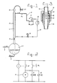
- Figure 1 is a schematic representation of the deaeration apparatus according to the invention;
- Figure 2 is an electric diagram for the operation of the apparatus, and
- Figure 3 is a cross-section of the metering blowoff apparatus.
- In Figure 1, 1 designates a receiver vessel containing liquid refrigerant and gas. The gas consists of vaporous refrigerant and non-condensable gases, such as air.
- The apparatus according to the invention seeks to remove these non-condensable gases periodically without losing an amount of refrigerant which is excessive from the economic point of view.
- A
pipe 2, coming from the condenser (not shown) of the refrigeration machine requiring deaeration, is connected to the top of the receiver vessel. The expression "deaeration" is thus used to mean not solely the removal of air, but also that of other non-condens able gases. - A
pipe 3, which leads to the evaporator (likewise not shown) of the refrigeration machine, is connected to the bottom of the receiver vessel 1. - A
vertical pipe 4 is also connected to the top of the vessel 1 and is provided with a shut-offvalve 5 between the vessel 1 and thepipe 4, ametering blowoff device 6, which will be discussed later on, and a shut-off valve V1. Thispipe 4 is thus not part of the circuit, although it is connected to it. - The
pipe 4 is surrounded by a jacket 7, through which refrigerant from a smaller secondary refrigeration machine is passed. This secondary refrigeration machine consists of apipe 8, acompressor 9, acondenser 10 and an operable expansion shut-off valve V2. The jacket 7 forms the evaporator. - Between the evaporator 7 and the
compressor 9 is disposed a pressure gauge Pc, which operates a switch PL in dependence on the suction pressure in the pipe 8 (see Figure 2). - Figure 2 shows the electrical diagram of the apparatus according to Figure 1. L designates therein a time clock adapted to operate a
switch 5. M designates the motor of thecompressor 9. - When S is closed, the
compressor 9 is in operation and the shut-off valves V1 and V2 are opened. - This is also the case when S is opened but Pc closes the secondary circuit, by means of the switch PL, under a determined pressure in the
pipe 8. - The apparatus shown in Figure 1 works as follows:
- The time clock L is set so that after for example 24 hours it closes the switch S and keeps it closed during a certain period of time, for example for five minutes. During this time Pc measures the suction pressure in the
pipe 8 upstream of thecompressor 9. - This suction pressure is a measure of the content of condensable gas and the content of non-condensable gas in the
tube 4. Condensable gas is formed by the refrigerant, such as freon or ammonia, and must as far as possible be retained. - With a high air content in the
pipe 4 the transfer of heat between the jacket 7 and thetube 4 is poor and the secondary refrigeration machine is well able to cool thetube 4 adequately. - The suction pressure in the
pipe 8 upstream of thecompressor 9 is then low. When the sensor Pc measures a suction pressure below a predetermined value, the switch PL is closed by Pc. Thecompressor 9 then continues to operate and the switches V₁ and V₂ remain open, despite the fact that the time clock L interrupts the switch S after five minutes. - In view of the fact that V₁ is open, non-condensable gas is blown off to the atmosphere during this time until the content of non-condensable gas in the
pipe 4 has fallen to such an extent that the transfer of heat between 7 and 4 is once again satisfactory. The suction pressure in thepipe 8 then rises above a determined adjusted value, and Pc switches off PL, so that the secondary refrigeration machine is stopped and V₁ is also closed. The blowoff is thus stopped until the time clock L switches on again. - If during the aforesaid period of five minutes it is already found that the air content in the
tube 4 is low, the suction pressure in thepipe 8 will be high and Pc will switch off the switch PL. At the end of the period of five minutes L will also switch off S, so that the secondary refrigeration machine will stop. - The apparatus according to the invention stops and the blowoff process thus starts automatically in dependence on the content of non-condensable gases.
- The known aspparatus blows off continuously, or else blowoff must be stopped or started manually. However in this case no information at all regarding the air content in the
tube 4 is available. The only known method is to connect to V₁ a bottle filled with water. If bubbles are seen to rise to the surface of the water, this means that air is contained in thepipe 4, but there is no indication of the amount of air. - In the case of the apparatus according to the invention the suction pressure in the
pipe 8 is a measure of the air content in thepipe 4. It had never been realized that use could be made of it. - In the apparatus according to the invention, moreover, blowoff is effected in a metered manner, and the
blowoff valve 6 can for this purpose be constructed as illustrated in Figure 3. The passage of theblowoff valve 6 is formed by a small tube 11 of stainless steel having, for example, an inside diameter of 0.05 mm and an outside diameter of 0.3 mm. The length of the tube 11 determines the blowoff capacity. With a pressure of for example 10 bars, 5 cubic centimetres of air per second, for example, are blown off. The user of the apparatus according to the invention thus knows accurately how much air is blown off during the blowoff operation. - The slender, vulnerable tube 11 can be mounted in a
plate 12 clamped in thepipe parts 13 and 14 by means of acoupling nut 15.
Claims (8)
Priority Applications (1)
| Application Number | Priority Date | Filing Date | Title |
|---|---|---|---|
| AT87201517T ATE52325T1 (en) | 1986-08-19 | 1987-08-10 | METHOD AND DEVICE FOR AUTOMATIC, PERIODIC VENTILATION OF A COMPRESSION REFRIGERATION CIRCUIT. |
Applications Claiming Priority (2)
| Application Number | Priority Date | Filing Date | Title |
|---|---|---|---|
| NL8602106A NL8602106A (en) | 1986-08-19 | 1986-08-19 | METHOD AND APPARATUS FOR AUTOMATIC PERIODICALLY EXTRACTING NON-CONDENSIBLE GASES FROM THE CIRCULATION OF A COMPRESSION CHILLER. |
| NL8602106 | 1986-08-19 |
Publications (2)
| Publication Number | Publication Date |
|---|---|
| EP0256602A1 true EP0256602A1 (en) | 1988-02-24 |
| EP0256602B1 EP0256602B1 (en) | 1990-04-25 |
Family
ID=19848427
Family Applications (1)
| Application Number | Title | Priority Date | Filing Date |
|---|---|---|---|
| EP87201517A Expired - Lifetime EP0256602B1 (en) | 1986-08-19 | 1987-08-10 | Method and apparatus for the automatic periodical discharge of non-condensable gases from the circuit of a compression refrigeration machine |
Country Status (8)
| Country | Link |
|---|---|
| US (1) | US4776175A (en) |
| EP (1) | EP0256602B1 (en) |
| AT (1) | ATE52325T1 (en) |
| DE (1) | DE3762453D1 (en) |
| ES (1) | ES2014020B3 (en) |
| GR (1) | GR3000450T3 (en) |
| NL (1) | NL8602106A (en) |
| ZA (1) | ZA875980B (en) |
Cited By (3)
| Publication number | Priority date | Publication date | Assignee | Title |
|---|---|---|---|---|
| EP3591316A1 (en) | 2018-07-06 | 2020-01-08 | Danfoss A/S | Apparatus for removing non-condensable gases from a refrigerant |
| US11549734B2 (en) | 2018-06-22 | 2023-01-10 | Danfoss A/S | Method for terminating defrosting of an evaporator by use of air temperature measurements |
| US12044450B2 (en) | 2018-06-22 | 2024-07-23 | Danfoss A/S | Method for terminating defrosting of an evaporator |
Families Citing this family (4)
| Publication number | Priority date | Publication date | Assignee | Title |
|---|---|---|---|---|
| US5040382A (en) * | 1990-06-19 | 1991-08-20 | 501 Wynn's Climate Systems, Inc. | Refrigerant recovery system |
| US5337578A (en) * | 1993-02-19 | 1994-08-16 | Wynn's Climate Systems, Inc. | Trapped air monitor for a refrigerant recovery unit |
| US5400613A (en) * | 1993-11-19 | 1995-03-28 | O'neal; Andrew | Purger for refrigeration system |
| US9759465B2 (en) | 2011-12-27 | 2017-09-12 | Carrier Corporation | Air conditioner self-charging and charge monitoring system |
Citations (8)
| Publication number | Priority date | Publication date | Assignee | Title |
|---|---|---|---|---|
| NL101674C (en) * | 1900-01-01 | |||
| US1744816A (en) * | 1926-11-18 | 1930-01-28 | Frigidaire Corp | Refrigerating apparatus |
| GB575884A (en) * | 1944-04-21 | 1946-03-08 | Standard Pressed Steel Co | Improvements in or relating to refrigerating systems |
| US2400620A (en) * | 1945-01-18 | 1946-05-21 | Worthington Pump & Mach Corp | Purging system for refrigerating systems |
| US3131548A (en) * | 1962-11-01 | 1964-05-05 | Worthington Corp | Refrigeration purge control |
| US3167928A (en) * | 1963-04-26 | 1965-02-02 | Electronic Specialty Co | Method of and apparatus for venting fixed gas from absorption refrigeration system |
| CH492939A (en) * | 1968-08-27 | 1970-06-30 | Linde Ag | Automatic venting device for refrigerant circuits, in particular in compression refrigeration machine systems |
| US4169356A (en) * | 1978-02-27 | 1979-10-02 | Lloyd Kingham | Refrigeration purge system |
Family Cites Families (3)
| Publication number | Priority date | Publication date | Assignee | Title |
|---|---|---|---|---|
| US3145544A (en) * | 1961-11-07 | 1964-08-25 | American Radiator & Standard | Refrigeration system impurity purge means |
| DE2334152B2 (en) * | 1973-07-05 | 1975-05-15 | Flachglas Ag Delog-Detag, 8510 Fuerth | Heat-reflecting, 20 to 60% of the visible light transmitting window pane with improved color neutrality in the view and its use |
| US4304102A (en) * | 1980-04-28 | 1981-12-08 | Carrier Corporation | Refrigeration purging system |
-
1986
- 1986-08-19 NL NL8602106A patent/NL8602106A/en not_active Application Discontinuation
-
1987
- 1987-08-10 ES ES87201517T patent/ES2014020B3/en not_active Expired - Lifetime
- 1987-08-10 AT AT87201517T patent/ATE52325T1/en not_active IP Right Cessation
- 1987-08-10 EP EP87201517A patent/EP0256602B1/en not_active Expired - Lifetime
- 1987-08-10 DE DE8787201517T patent/DE3762453D1/en not_active Expired - Fee Related
- 1987-08-12 ZA ZA875980A patent/ZA875980B/en unknown
- 1987-08-19 US US07/086,738 patent/US4776175A/en not_active Expired - Lifetime
-
1990
- 1990-04-26 GR GR90400196T patent/GR3000450T3/en unknown
Patent Citations (8)
| Publication number | Priority date | Publication date | Assignee | Title |
|---|---|---|---|---|
| NL101674C (en) * | 1900-01-01 | |||
| US1744816A (en) * | 1926-11-18 | 1930-01-28 | Frigidaire Corp | Refrigerating apparatus |
| GB575884A (en) * | 1944-04-21 | 1946-03-08 | Standard Pressed Steel Co | Improvements in or relating to refrigerating systems |
| US2400620A (en) * | 1945-01-18 | 1946-05-21 | Worthington Pump & Mach Corp | Purging system for refrigerating systems |
| US3131548A (en) * | 1962-11-01 | 1964-05-05 | Worthington Corp | Refrigeration purge control |
| US3167928A (en) * | 1963-04-26 | 1965-02-02 | Electronic Specialty Co | Method of and apparatus for venting fixed gas from absorption refrigeration system |
| CH492939A (en) * | 1968-08-27 | 1970-06-30 | Linde Ag | Automatic venting device for refrigerant circuits, in particular in compression refrigeration machine systems |
| US4169356A (en) * | 1978-02-27 | 1979-10-02 | Lloyd Kingham | Refrigeration purge system |
Cited By (6)
| Publication number | Priority date | Publication date | Assignee | Title |
|---|---|---|---|---|
| US11549734B2 (en) | 2018-06-22 | 2023-01-10 | Danfoss A/S | Method for terminating defrosting of an evaporator by use of air temperature measurements |
| US12044450B2 (en) | 2018-06-22 | 2024-07-23 | Danfoss A/S | Method for terminating defrosting of an evaporator |
| EP3591316A1 (en) | 2018-07-06 | 2020-01-08 | Danfoss A/S | Apparatus for removing non-condensable gases from a refrigerant |
| WO2020007866A1 (en) | 2018-07-06 | 2020-01-09 | Danfoss A/S | Apparatus for removing non-condensable gases from a refrigerant |
| CN112204323A (en) * | 2018-07-06 | 2021-01-08 | 丹佛斯有限公司 | Apparatus for removing non-condensable gases from a refrigerant |
| US11365919B2 (en) | 2018-07-06 | 2022-06-21 | Danfoss A/S | Apparatus for removing non-condensable gases from a refrigerant |
Also Published As
| Publication number | Publication date |
|---|---|
| ATE52325T1 (en) | 1990-05-15 |
| ES2014020B3 (en) | 1990-06-16 |
| EP0256602B1 (en) | 1990-04-25 |
| GR3000450T3 (en) | 1991-06-28 |
| US4776175A (en) | 1988-10-11 |
| ZA875980B (en) | 1988-02-19 |
| DE3762453D1 (en) | 1990-05-31 |
| NL8602106A (en) | 1988-03-16 |
Similar Documents
| Publication | Publication Date | Title |
|---|---|---|
| US5875638A (en) | Refrigerant recovery system | |
| US5046325A (en) | Refrigerating circuit apparatus with two stage compressor and heat storage tank | |
| US6119472A (en) | Ice cream machine optimized to efficiently and evenly freeze ice cream | |
| US6370892B1 (en) | Batch process and apparatus optimized to efficiently and evenly freeze ice cream | |
| US5291743A (en) | Refrigerant reclaim with automatic air purge | |
| EP0256602A1 (en) | Method and apparatus for the automatic periodical discharge of non-condensable gases from the circuit of a compression refrigeration machine | |
| US4976116A (en) | Cold-air generating device | |
| JPH0792299B2 (en) | Refrigerant recovery method and recovery device | |
| AU616829B2 (en) | Refrigerant processing and charging system | |
| US4718245A (en) | Refrigeration system with bypass valves | |
| US5465590A (en) | Refrigerant reclaim with air purge | |
| US3224212A (en) | Process and apparatus for continuously dehydrating gas | |
| JPH04506248A (en) | Compression refrigeration equipment equipped with oil separator | |
| JP4008393B2 (en) | Water cooler | |
| US5921097A (en) | Purge processor | |
| JP2880478B2 (en) | Drain discharge controller of refrigeration air dryer and refrigeration air dryer | |
| KR100510695B1 (en) | Quick Cooling Device | |
| JP2643671B2 (en) | Operation control device for refrigeration equipment | |
| KR970004339B1 (en) | Impurity Gas Removal Device | |
| KR940010584B1 (en) | Refrigerator | |
| SU1693326A1 (en) | Refrigerating plant | |
| JPH04268179A (en) | Device for control of defrosting of air conditioner | |
| KR200181954Y1 (en) | Apparatus for cooling water in the water cooling-warming machine or water cleaning machine | |
| JPS56108501A (en) | Refrigerator for compressed air | |
| SU841464A1 (en) | Refrigeration unit |
Legal Events
| Date | Code | Title | Description |
|---|---|---|---|
| PUAI | Public reference made under article 153(3) epc to a published international application that has entered the european phase |
Free format text: ORIGINAL CODE: 0009012 |
|
| AK | Designated contracting states |
Kind code of ref document: A1 Designated state(s): AT BE CH DE ES FR GB GR IT LI LU NL SE |
|
| 17P | Request for examination filed |
Effective date: 19880111 |
|
| 17Q | First examination report despatched |
Effective date: 19880926 |
|
| GRAA | (expected) grant |
Free format text: ORIGINAL CODE: 0009210 |
|
| AK | Designated contracting states |
Kind code of ref document: B1 Designated state(s): AT BE CH DE ES FR GB GR IT LI LU NL SE |
|
| REF | Corresponds to: |
Ref document number: 52325 Country of ref document: AT Date of ref document: 19900515 Kind code of ref document: T |
|
| ITF | It: translation for a ep patent filed | ||
| REF | Corresponds to: |
Ref document number: 3762453 Country of ref document: DE Date of ref document: 19900531 |
|
| ET | Fr: translation filed | ||
| REG | Reference to a national code |
Ref country code: GR Ref legal event code: FG4A Free format text: 3000450 |
|
| PLBE | No opposition filed within time limit |
Free format text: ORIGINAL CODE: 0009261 |
|
| STAA | Information on the status of an ep patent application or granted ep patent |
Free format text: STATUS: NO OPPOSITION FILED WITHIN TIME LIMIT |
|
| 26N | No opposition filed | ||
| ITTA | It: last paid annual fee | ||
| EPTA | Lu: last paid annual fee | ||
| EAL | Se: european patent in force in sweden |
Ref document number: 87201517.7 |
|
| GBPC | Gb: european patent ceased through non-payment of renewal fee |
Effective date: 19950810 |
|
| REG | Reference to a national code |
Ref country code: GB Ref legal event code: 728V |
|
| REG | Reference to a national code |
Ref country code: GB Ref legal event code: 728Y |
|
| REG | Reference to a national code |
Ref country code: GB Ref legal event code: IF02 |
|
| PGFP | Annual fee paid to national office [announced via postgrant information from national office to epo] |
Ref country code: ES Payment date: 20030619 Year of fee payment: 17 |
|
| PGFP | Annual fee paid to national office [announced via postgrant information from national office to epo] |
Ref country code: GR Payment date: 20030620 Year of fee payment: 17 |
|
| PGFP | Annual fee paid to national office [announced via postgrant information from national office to epo] |
Ref country code: NL Payment date: 20030630 Year of fee payment: 17 |
|
| PGFP | Annual fee paid to national office [announced via postgrant information from national office to epo] |
Ref country code: SE Payment date: 20030806 Year of fee payment: 17 Ref country code: GB Payment date: 20030806 Year of fee payment: 17 |
|
| PGFP | Annual fee paid to national office [announced via postgrant information from national office to epo] |
Ref country code: FR Payment date: 20030808 Year of fee payment: 17 |
|
| PGFP | Annual fee paid to national office [announced via postgrant information from national office to epo] |
Ref country code: LU Payment date: 20030813 Year of fee payment: 17 Ref country code: AT Payment date: 20030813 Year of fee payment: 17 |
|
| PGFP | Annual fee paid to national office [announced via postgrant information from national office to epo] |
Ref country code: CH Payment date: 20030818 Year of fee payment: 17 |
|
| PGFP | Annual fee paid to national office [announced via postgrant information from national office to epo] |
Ref country code: DE Payment date: 20030822 Year of fee payment: 17 |
|
| PGFP | Annual fee paid to national office [announced via postgrant information from national office to epo] |
Ref country code: BE Payment date: 20031009 Year of fee payment: 17 |
|
| PG25 | Lapsed in a contracting state [announced via postgrant information from national office to epo] |
Ref country code: LU Free format text: LAPSE BECAUSE OF NON-PAYMENT OF DUE FEES Effective date: 20040810 Ref country code: GB Free format text: LAPSE BECAUSE OF NON-PAYMENT OF DUE FEES Effective date: 20040810 Ref country code: AT Free format text: LAPSE BECAUSE OF NON-PAYMENT OF DUE FEES Effective date: 20040810 |
|
| PG25 | Lapsed in a contracting state [announced via postgrant information from national office to epo] |
Ref country code: SE Free format text: LAPSE BECAUSE OF NON-PAYMENT OF DUE FEES Effective date: 20040811 Ref country code: ES Free format text: LAPSE BECAUSE OF NON-PAYMENT OF DUE FEES Effective date: 20040811 |
|
| PG25 | Lapsed in a contracting state [announced via postgrant information from national office to epo] |
Ref country code: LI Free format text: LAPSE BECAUSE OF NON-PAYMENT OF DUE FEES Effective date: 20040831 Ref country code: CH Free format text: LAPSE BECAUSE OF NON-PAYMENT OF DUE FEES Effective date: 20040831 Ref country code: BE Free format text: LAPSE BECAUSE OF NON-PAYMENT OF DUE FEES Effective date: 20040831 |
|
| BERE | Be: lapsed |
Owner name: *GRASSO'S KONINKLIJKE MACHINEFABRIEKEN N.V. Effective date: 20040831 |
|
| PG25 | Lapsed in a contracting state [announced via postgrant information from national office to epo] |
Ref country code: NL Free format text: LAPSE BECAUSE OF NON-PAYMENT OF DUE FEES Effective date: 20050301 Ref country code: DE Free format text: LAPSE BECAUSE OF NON-PAYMENT OF DUE FEES Effective date: 20050301 |
|
| PG25 | Lapsed in a contracting state [announced via postgrant information from national office to epo] |
Ref country code: GR Free format text: LAPSE BECAUSE OF NON-PAYMENT OF DUE FEES Effective date: 20050303 |
|
| EUG | Se: european patent has lapsed | ||
| GBPC | Gb: european patent ceased through non-payment of renewal fee |
Effective date: 20040810 |
|
| REG | Reference to a national code |
Ref country code: CH Ref legal event code: PL |
|
| PG25 | Lapsed in a contracting state [announced via postgrant information from national office to epo] |
Ref country code: FR Free format text: LAPSE BECAUSE OF NON-PAYMENT OF DUE FEES Effective date: 20050429 |
|
| NLV4 | Nl: lapsed or anulled due to non-payment of the annual fee |
Effective date: 20050301 |
|
| REG | Reference to a national code |
Ref country code: FR Ref legal event code: ST |
|
| PG25 | Lapsed in a contracting state [announced via postgrant information from national office to epo] |
Ref country code: IT Free format text: LAPSE BECAUSE OF NON-PAYMENT OF DUE FEES;WARNING: LAPSES OF ITALIAN PATENTS WITH EFFECTIVE DATE BEFORE 2007 MAY HAVE OCCURRED AT ANY TIME BEFORE 2007. THE CORRECT EFFECTIVE DATE MAY BE DIFFERENT FROM THE ONE RECORDED. Effective date: 20050810 |
|
| REG | Reference to a national code |
Ref country code: ES Ref legal event code: FD2A Effective date: 20040811 |
|
| BERE | Be: lapsed |
Owner name: *GRASSO'S KONINKLIJKE MACHINEFABRIEKEN N.V. Effective date: 20040831 |