EP0255907A2 - Machine for topping agricultural products - Google Patents
Machine for topping agricultural products Download PDFInfo
- Publication number
- EP0255907A2 EP0255907A2 EP87110875A EP87110875A EP0255907A2 EP 0255907 A2 EP0255907 A2 EP 0255907A2 EP 87110875 A EP87110875 A EP 87110875A EP 87110875 A EP87110875 A EP 87110875A EP 0255907 A2 EP0255907 A2 EP 0255907A2
- Authority
- EP
- European Patent Office
- Prior art keywords
- containers
- machine according
- products
- machine
- respect
- Prior art date
- Legal status (The legal status is an assumption and is not a legal conclusion. Google has not performed a legal analysis and makes no representation as to the accuracy of the status listed.)
- Withdrawn
Links
Images


Classifications
-
- A—HUMAN NECESSITIES
- A23—FOODS OR FOODSTUFFS; TREATMENT THEREOF, NOT COVERED BY OTHER CLASSES
- A23N—MACHINES OR APPARATUS FOR TREATING HARVESTED FRUIT, VEGETABLES OR FLOWER BULBS IN BULK, NOT OTHERWISE PROVIDED FOR; PEELING VEGETABLES OR FRUIT IN BULK; APPARATUS FOR PREPARING ANIMAL FEEDING- STUFFS
- A23N15/00—Machines or apparatus for other treatment of fruits or vegetables for human purposes; Machines or apparatus for topping or skinning flower bulbs
- A23N15/04—Devices for topping fruit or vegetables
Definitions
- the present invention relates to a stemming machine, particularly usable for horticultural products.
- the main aim of the present invention is therefore to eliminate the disadvantages described above in known types, by devising a machine which allows to perform the cutting of the ends of horticultural products such as courgettes, cucumbers, carrots, etc., automatically without the intervention of personnel.
- an important object is to devise a machine which, taking said products, also allows a correct positioning thereof in the cutting step.
- Another important object is to provide a machine which adds to the preceding characteristics that of being able to achieve a high productivity.
- a stemming machine particularly for horticultural products, characterized in that it comprises a conveyor belt composed of a plurality of individual swivelling containers guided on sequential counterposed inclined planes, said machine comprising at least two stations for cutting according to an adjustable depth at the most inclined regions of said containers, with said machine there being associated means for the positioning and the securing of said products within said containers.
- the reference numeral 1 indicates a stemming machine particularly usable for horticultural products, indicated by the numeral 2, such as cucumbers, courgettes, carrots, egg-plants, etc.
- Said machine 1 comprises a framework 3 which supports a motorized conveyor belt 4 which in turn consists of a plurality of individual containers 5 arranged side by side to one another.
- These containers are composed of a cup with an essentially V-shaped transverse cross section, and have such dimensions as to accommodate horticultural products having lengths or diameters different from one another.
- each of said containers 5 is provided with elements for connection to means for moving the belt, consisting of rods 6 welded at the lower surface thereof.
- Each of said rods is pivoted to the flaps of a connecting element consisting of an essentially U-shaped section 7, said section being retained on a chain 8 which constitutes, together with a suitable motor, the means for the movement of the belt 4.
- each individual container 5 rest on adapted lateral guides 9 and 10.
- These guides are arranged so that the containers 5 which are slideable thereon have a variable plane of arrangement according to the movement of said belt, said containers 5 being arranged, in a first region 11, on a horizontal plane, then, in a second region 12, on a transversely inclined plane, subsequently passing in a third region 13 wherein said containers are arranged on a plane inclined in the opposite direction with respect to that of said second region.
- two rods 17a and 17b are associated at one end with an eccentric element 18 rotated by a shaft 19 keyed on an adapted motor, and are connected to these portions 14 and 15 by means of an interposed elastically deformable element consisting of a spring 16.
- a vibrating assembly is thus defined wherein the portions 14 and 15 transmit to the individual containers 5 an alternate periodic motion such as to position the horticultural products contained therein alternately adjacent to the lateral walls 20 and 21 of the framework 3 between which slides the belt 4.
- a first cutting station 22 is provided and consists of a rotating blade 23 which is movable along planes parallel with respect to said wall 20.
- Said blade is operated by an electric motor 24, rigidly associated with a plate 25 which is slideable with respect to a first small frame 26 projecting from the wall 20, the movement along planes parallel to that of said wall 20 being allowed by a screw 27 an end whereof is connected to the plate 25, the other end interacting with a complementary threaded sleeve 28 rigidly associated with a bar 29 transversely coupled to a pair of lateral uprights 30a and 30b the ends whereof are associated respectively with the first frame 26 and with the wall 21 of the framework 3.
- a means for the securing of the products 2 in the containers 5 before and during the cutting step is associated with the plate 25.
- Said means consists of a toothed wheel 31 adjacent to the rotating blade 23 and interacting with the products before the blade.
- the teeth of the wheel are in fact shaped complementarily with respect to the seats of the containers 5 and are preferably made of elastically deformable plastic material so as to avoid ruining the product's shape, adapting thereto.
- the toothed wheel 31 is pivoted to an arm 32 associated with the plate 25 and projecting below it.
- the products Once the products are placed in the container 5, for example by means of a conveyor belt which takes said products from a hopper, the products tend to place themselves by gravity against the wall 20 when said containers begin to arrange themselves inclined upon reaching the first region 12.
- the products In the motion of the belt, the products interact with the toothed wheel 31 which secures them in the correct position during the step of cutting one of their ends by means of the blade 23.
- the cut-off pieces fall onto a conveyor 33 underlying the region of said blade.
- the products, one end whereof is already cut are carried by the belt 4 to the third region 13 wherein the containers are arranged again inclined, but on the opposite side with respect to the previous one, so that the still uncut end of the product arranges itself adjacent to the wall 21.
- a second cutting station 34 similar to the preceding one and arranged adjacent to the wall 21, is provided.
- the station consists of a rotating blade, movable along planes which are parallel to that of the wall 21, and is operated by a motor 35 rigidly associated with a plate which is slideable with respect to a second small frame 36.
- a screw 37 is similar to the one 27 is provided for the positioning of the blade according to the desired cutting depth.
- a means for the securing of the products 2 in the containers 5 before and during the cutting step consisting of a second toothed wheel 38 arranged adjacent to the blade, is associated with the plate.
- This wheel is provided with teeth which are shaped complementarily with respect to the seats of the containers 5 and are made of elastically deformable plastic material so as to avoid ruining the horticultural products, adapting thereto.
- the belt After passing the second region 14, the belt unloads the stemmed products through a duct 39 provided at the terminal end of the machine 1.
- the machine is furthermore provided with a control panel 40 to operate the motors 24, 33 and of the motors which drive the chain 8 and the shaft 19.
- the selected cutting depth can be obtained by moving a partition 41 which is movable with respect to the ends of the containers 5 and to the plane of arrangement of the lateral walls 20 and 21.
- a two-blade third cutting station 42 adapted to further cut the processed product which exits from the machine 1 is conveniently provided at the terminal end of the conveyor belt 4.
- the blades of this station are arranged on planes perpendicular to the plane of arrangement of the containers 5 facing said station so as to reduce the length of the processed products and to allow, for example, their successive conveyance to a dicing or slicing machine.
- the products obtained have uniformly precise stemmed ends by virtue of the inclination imparted to the containers 5 and of the vibratory motion imparted to the same in the regions of greater inclination.
- the chain 8 which has a loop-like configuration, is entrained at the ends of the machine on adapted crown wheels 43, at least one whereof is a driving crown wheel, its shaft 44 being pivoted on a slider 45 which is movable on a side member 46 of the framework and is articulated, by means of an arm 47, to the end of a rod 48a, also pivoted eccentrically to the framework 3 and, at the other end, to an adjustable tensioning element 49 connected to the framework 3 by means of a spring 50.
- the optimum tensioning of the chain 8 during the operation of the machine is thus obtained.
- a small tooth is provided which interacts with a rack 48b associated with an element 48c rigidly associated with the framework so as to cause the unidirectional tensioning of the chain.
- Figures 6 and 7 instead illustrate further means for the correct positioning of the horticultural products 2 within the containers 5: they consist of three straightening brushes arranged above the containers 5, of which two are positioned side by side between the machine inlet end for the product to be stemmed and the toothed wheel 31 and the third is arranged between the first cutting station 22 and the second toothed wheel 38.
- Each of said brushes is rigidly associated with a disc 52, arranged on a plane approximately parallel to the plane of arrangement of the underlying inclined containers 5, and rotating by means of an adapted motor 53.
- Said brush is provided with a plurality of elastic appendages 54 skimming the containers, their function being to pull along, straightening them, the horticultural products 2 arranged transversely with respect to said containers 5.
- the brushes are arranged adjacent to the lateral wall of the machine whereon rest the horticultural products 2, on said wall there being provided, before the brush, a guide 55 adapted to remove from said wall the horticultural products 2 arranged longitudinally with respect to said machine.
- a water system having fan-like nozzles 56.
- the electrical plant of the machine is accordingly made waterproof by having the conductors 57 pass within an adapted duct 58 arranged above the conveyor belt.
- Figure 8 illustrates a cutting station wherein the rotating blade 23 has its shaft pivoted to a plate 25, also supporting the electric motor 24.
- the pulleys 59 and 60 for the transmission of the motion by means of the belt 61 are keyed to said shaft and said electric motor.
- the plate 25 is advantageously pivoted at one end to a pivot 62 projecting from said framework, parallel and eccentric to the pivoting shaft of the rotating blade 23. Said blade can thus oscillate for example if it makes contact with foreign objects, such as a stone.
- the materials, as well as the dimensions of the individual elements constituting the machine, may also be the most adapted according to the specific requirements.
Abstract
Topping machine (1), particularly for agricultural products (2), comprising a conveyor belt (4) composed of a plurality of individual containers (5) which are swivelling and guided on counterposed and sequential inclined planes. The machine (1) furthermore comprises stations (22,34) for cutting at a selective depth, as well as means (31,38) adapted to secure said products within said containers (5) during the cutting steps.
Description
- The present invention relates to a stemming machine, particularly usable for horticultural products.
- Currently, if horticultural products such as for example courgettes, cucumbers, carrots, etc., are to be treated, it is necessary for the same to be processed beforehand to remove their ends.
- These ends are in fact not edible and therefore must be eliminated before any cutting and/or cooking and/or packaging steps.
- Currently this stemming of horticultural products is usually performed manually, using personnel the cost whereof is such as to considerably affect the overall processing cost of these products.
- The only machine used for cutting the ends of said products is a circular blade: this however always leaves in any case to an operator the steps of taking the products and of placing the same next to said blade.
- The main aim of the present invention is therefore to eliminate the disadvantages described above in known types, by devising a machine which allows to perform the cutting of the ends of horticultural products such as courgettes, cucumbers, carrots, etc., automatically without the intervention of personnel.
- Within the scope of the above described aim, an important object is to devise a machine which, taking said products, also allows a correct positioning thereof in the cutting step.
- Another important object is to provide a machine which adds to the preceding characteristics that of being able to achieve a high productivity.
- The aim and the objects described above, as well as others which will become apparent hereinafter, are achieved by a stemming machine, particularly for horticultural products, characterized in that it comprises a conveyor belt composed of a plurality of individual swivelling containers guided on sequential counterposed inclined planes, said machine comprising at least two stations for cutting according to an adjustable depth at the most inclined regions of said containers, with said machine there being associated means for the positioning and the securing of said products within said containers.
- Further characteristics and advantages of the invention will become apparent from the description of a particular, but not exclusive, embodiment, illustrated only by way of non-limitative example in the accompanying drawings, wherein:
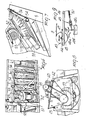
- Fig. 1 is a perspective side view of the machine;
- Fig. 2 is a perspective front view of the machine from the front end thereof wherefrom the processed product exits;
- Fig. 3 is a perspective view of one of the cutting stations;
- Fig. 4 is a view of the guides whereon the containers slide and the means for their movement;
- Fig. 5 is a cross section view of a container;
- Figs. 6 and 7 are respectively top and lateral perspective views of further means for the correct positioning of the horticultural products within the containers;
- Fig. 8 is a lateral view of an oscillating cutting station; and
- Fig. 9 finally is a view of a chain tensioner applied to the machine.
- With reference to the above described drawings, the reference numeral 1 indicates a stemming machine particularly usable for horticultural products, indicated by the
numeral 2, such as cucumbers, courgettes, carrots, egg-plants, etc. - Said machine 1 comprises a
framework 3 which supports a motorized conveyor belt 4 which in turn consists of a plurality ofindividual containers 5 arranged side by side to one another. - These containers are composed of a cup with an essentially V-shaped transverse cross section, and have such dimensions as to accommodate horticultural products having lengths or diameters different from one another.
- At its transverse middle axis, each of said
containers 5 is provided with elements for connection to means for moving the belt, consisting of rods 6 welded at the lower surface thereof. - Each of said rods is pivoted to the flaps of a connecting element consisting of an essentially U-shaped
section 7, said section being retained on achain 8 which constitutes, together with a suitable motor, the means for the movement of the belt 4. - During the movement of said belt, the lateral ends of each
individual container 5 rest on adaptedlateral guides 9 and 10. - These guides are arranged so that the
containers 5 which are slideable thereon have a variable plane of arrangement according to the movement of said belt, saidcontainers 5 being arranged, in a first region 11, on a horizontal plane, then, in asecond region 12, on a transversely inclined plane, subsequently passing in athird region 13 wherein said containers are arranged on a plane inclined in the opposite direction with respect to that of said second region. - This arrangement of the
guides 9 and 10 is illustrated in fig. 4, which points out that theseguides 9 and 10 have, at each end of theregions portions - In fact, two rods 17a and 17b are associated at one end with an
eccentric element 18 rotated by a shaft 19 keyed on an adapted motor, and are connected to theseportions spring 16. - A vibrating assembly is thus defined wherein the
portions individual containers 5 an alternate periodic motion such as to position the horticultural products contained therein alternately adjacent to thelateral walls framework 3 between which slides the belt 4. - At the
wall 20 and adjacent to it in thesecond region 12 of maximum inclination, afirst cutting station 22 is provided and consists of a rotatingblade 23 which is movable along planes parallel with respect to saidwall 20. - Said blade is operated by an
electric motor 24, rigidly associated with aplate 25 which is slideable with respect to a firstsmall frame 26 projecting from thewall 20, the movement along planes parallel to that ofsaid wall 20 being allowed by ascrew 27 an end whereof is connected to theplate 25, the other end interacting with a complementary threadedsleeve 28 rigidly associated with abar 29 transversely coupled to a pair oflateral uprights 30a and 30b the ends whereof are associated respectively with thefirst frame 26 and with thewall 21 of theframework 3. - A means for the securing of the
products 2 in thecontainers 5 before and during the cutting step is associated with theplate 25. - Said means consists of a
toothed wheel 31 adjacent to the rotatingblade 23 and interacting with the products before the blade. - The teeth of the wheel are in fact shaped complementarily with respect to the seats of the
containers 5 and are preferably made of elastically deformable plastic material so as to avoid ruining the product's shape, adapting thereto. - The
toothed wheel 31 is pivoted to anarm 32 associated with theplate 25 and projecting below it. - Once the products are placed in the
container 5, for example by means of a conveyor belt which takes said products from a hopper, the products tend to place themselves by gravity against thewall 20 when said containers begin to arrange themselves inclined upon reaching thefirst region 12. - This setting is ensured by the vibratory motion imparted to the
portions guides 9 and 10. - In the motion of the belt, the products interact with the
toothed wheel 31 which secures them in the correct position during the step of cutting one of their ends by means of theblade 23. - The cut-off pieces fall onto a
conveyor 33 underlying the region of said blade. - After passing the
second region 12, the products, one end whereof is already cut, are carried by the belt 4 to thethird region 13 wherein the containers are arranged again inclined, but on the opposite side with respect to the previous one, so that the still uncut end of the product arranges itself adjacent to thewall 21. - At this point a
second cutting station 34, similar to the preceding one and arranged adjacent to thewall 21, is provided. - Also in this case, the station consists of a rotating blade, movable along planes which are parallel to that of the
wall 21, and is operated by amotor 35 rigidly associated with a plate which is slideable with respect to a secondsmall frame 36. - Naturally, a
screw 37 is similar to the one 27 is provided for the positioning of the blade according to the desired cutting depth. - A means for the securing of the
products 2 in thecontainers 5 before and during the cutting step, consisting of a secondtoothed wheel 38 arranged adjacent to the blade, is associated with the plate. - This wheel is provided with teeth which are shaped complementarily with respect to the seats of the
containers 5 and are made of elastically deformable plastic material so as to avoid ruining the horticultural products, adapting thereto. - After passing the
second region 14, the belt unloads the stemmed products through aduct 39 provided at the terminal end of the machine 1. - The machine is furthermore provided with a
control panel 40 to operate themotors chain 8 and the shaft 19. - Thus, for example, the selected cutting depth can be obtained by moving a
partition 41 which is movable with respect to the ends of thecontainers 5 and to the plane of arrangement of thelateral walls - The spacing of this
wall 41 from the ends of the containers determines the cutting depth, since the products rest one of their ends on this wall. - Moreover, a two-blade
third cutting station 42 adapted to further cut the processed product which exits from the machine 1 is conveniently provided at the terminal end of the conveyor belt 4. - The blades of this station are arranged on planes perpendicular to the plane of arrangement of the
containers 5 facing said station so as to reduce the length of the processed products and to allow, for example, their successive conveyance to a dicing or slicing machine. - It has thus been observed that the invention achieves the intended aim and objets, a machine having been obtained which allows to cut the terminal ends of products such as courgettes, cucumbers and carrots automatically and rapidly.
- The processing costs are thus considerably reduced, obtaining output products ready for the subsequent operations, which vary according to the destination of said products.
- Finally, the products obtained have uniformly precise stemmed ends by virtue of the inclination imparted to the
containers 5 and of the vibratory motion imparted to the same in the regions of greater inclination. - Naturally, the invention is susceptible to numerous modifications and variations, all of which are within the scope of the same inventive concept. Thus, for example, the
chain 8, which has a loop-like configuration, is entrained at the ends of the machine on adaptedcrown wheels 43, at least one whereof is a driving crown wheel, itsshaft 44 being pivoted on aslider 45 which is movable on aside member 46 of the framework and is articulated, by means of anarm 47, to the end of arod 48a, also pivoted eccentrically to theframework 3 and, at the other end, to anadjustable tensioning element 49 connected to theframework 3 by means of aspring 50. The optimum tensioning of thechain 8 during the operation of the machine is thus obtained. At the free end of therod 48a a small tooth is provided which interacts with a rack 48b associated with an element 48c rigidly associated with the framework so as to cause the unidirectional tensioning of the chain. - Figures 6 and 7 instead illustrate further means for the correct positioning of the
horticultural products 2 within the containers 5: they consist of three straightening brushes arranged above thecontainers 5, of which two are positioned side by side between the machine inlet end for the product to be stemmed and thetoothed wheel 31 and the third is arranged between thefirst cutting station 22 and the secondtoothed wheel 38. - Each of said brushes, indicated by the
numeral 51, is rigidly associated with adisc 52, arranged on a plane approximately parallel to the plane of arrangement of the underlyinginclined containers 5, and rotating by means of an adaptedmotor 53. - Said brush is provided with a plurality of
elastic appendages 54 skimming the containers, their function being to pull along, straightening them, thehorticultural products 2 arranged transversely with respect to saidcontainers 5. - In order to facilitate this operation, the brushes are arranged adjacent to the lateral wall of the machine whereon rest the
horticultural products 2, on said wall there being provided, before the brush, aguide 55 adapted to remove from said wall thehorticultural products 2 arranged longitudinally with respect to said machine. - Moreover, in order to facilitate the sliding of the
horticultural products 2 within thecontainers 5, a water system is provided having fan-like nozzles 56. - Advantageously, the electrical plant of the machine is accordingly made waterproof by having the conductors 57 pass within an adapted
duct 58 arranged above the conveyor belt. - Figure 8 illustrates a cutting station wherein the rotating
blade 23 has its shaft pivoted to aplate 25, also supporting theelectric motor 24. Thepulleys belt 61 are keyed to said shaft and said electric motor. - The
plate 25 is advantageously pivoted at one end to a pivot 62 projecting from said framework, parallel and eccentric to the pivoting shaft of therotating blade 23. Said blade can thus oscillate for example if it makes contact with foreign objects, such as a stone. - The materials, as well as the dimensions of the individual elements constituting the machine, may also be the most adapted according to the specific requirements.
Claims (18)
1. Machine (1), particularly for horticultural products (2), characterized in that it comprises a conveyor belt (4) composed of a plurality of individual swivelling containers (5) guided on sequential counterposed inclined planes, said machine (1) further comprising at least two stations (22,34) for cutting said products, according to an adjustable depth, at the most inclined regions (12,13) of said containers (5), with said machine there being associated means (31,38) for the positioning and the securing of said products (2) within said containers (5).
2. Machine according to claim 1, characterized in that said conveyor belt (4) is motorized, said containers (5) being arranged side by side to one another and consisting of a cup having an essentially V-shaped transverse cross section, said containers (5) having such dimensions as to accommodate horticultural products (2) having different lengths or diameters with respect to one another.
3. Machine according to claims 1 and 2, characterized in that each of said containers (5) is downwardly provided, at its transverse middle axis, with elements for connection to means for moving said belt, said elements consisting of rods (6), said means consisting of a chain (8) operated by means of an adapted motor.
4. Machine according to the preceding claims, characterized in that said rods (6) of said containers (5) are pivoted to the flaps of an element for connecting to said chain consisting of an essentially U-shaped section (7).
5. Machine according to claims 1 and 4, characterized in that during the movement of said belt (4) the lateral ends of each of said containers (5) rest on adapted lateral guides (9,10), said guides being arranged so that said containers (5) slideable thereon have a plane of arrangement which varies according to the movement of said belt, said containers being arranged at a first region (11) on a horizontal plane, then at a second region (12) on an inclined plane, subsequently passing to a third region (13) where they are arranged on a plane inclined in the opposite direction with respect to that of said second region (12).
6. Machine according to claims 1 and 5, characterized in that said guides (9,10) are provided, at each of said second (12) and third (13) regions, with two portions (14,15) mechanically uncoupled therefrom, to said portions (14,15) there being connected an adapted means (16,17,18,19) for causing said portions (14,15) to vibrate.
7. Machine according to claims 1 and 6, characterized in that said means adapted to impart vibrations to said portions (14,15) mechanically uncoupled from said guides (9,10) consists of an elastically deformable element (16) the ends whereof are associated with said portions and with a rod (17a,17b) associated, at its other end, with an eccentric element (18) caused to rotate by means of an adapted shaft (19) keyed on an adapted motor.
8. Machine according to the preceding claims, characterized in that said belt (4) slides between two lateral walls (20,21), on one of said walls (20) there being provided, in said second region (12), a first cutting station (22) consisting of a rotating blade (23) which is movable on planes parallel to said wall (20), said blade (23) being operated by an electric motor (24) rigidly associated with a plate (25) which is slideable with respect to a first small frame (26) projecting from said wall (20), the motion according to planes parallel to the latter being allowed by a screw (27) an end whereof is connected to said plate (25), the other one interacting with a complementarily threaded sleeve (28) rigidly associated with a bar (29) which is transversely rigidly coupled to a pair of lateral uprights (30a,30b) the ends whereof are respectively rigidly associated with said first small frame (26) and with the opposite wall (21).
9. Machine according to the preceding claims, characterized in that it comprises a means for the securing of said products (2) in said containers (5) before and during the cutting step, said means consisting of a toothed wheel (31) adjacent to said rotating blade (23) and interacting with the products (2) before said blade, the teeth of said wheel being shaped complementarily with respect to the seats of said containers (5) and being preferably made of elastically deformable plastic material, said wheel (31) being pivoted to an arm (32) associated and projecting below said plate (25) which is slideable with respect to said first small frame (26).
10. Machine according to the preceding claims, characterized in that it comprises a second cutting station (34), similar to said first cutting station (22), arranged at said third region (13) in which said containers (5) are arranged on a plane which is inclined in the opposite direction with respect to that of said second region (12).
11. Machine according to the preceding claims, characterized in that it comprises, at each of said first (22) and second (34) cutting stations, a conveyor (33) adapted to recover the cut ends of said horticultural products (2).
12. Machine according to the preceding claims, characterized in that said cutting depth can be adjusted by moving a partition (41) which is movable with respect to the ends of said containers (5) and to the plane of arrangement of one of said lateral walls (20,21) between which said conveyor belt (4) slides, on said movable partition (41) there resting an end of said horticultural products (2).
13. Machine according to the preceding claims, characterized in that at the terminal end of said conveyor belt (4) a third, double-blade cutting station (42) is provided and is adapted to further cut said processed horticultural products (2), the blades of said third station being arranged on planes perpendicular to the planes of arrangement of said containers (5).
14. Machine according to claims 1 and 3, characterized in that said chain (8) is entrained on adapted crown wheels (43) at least one whereof is pivoted on a slider (45), movable with respect to said framework (3), and articulated to the end of a rod (48a), the latter being pivoted eccentrically to said framework (3), interacting with an adjustable tensioning element (49) connected to said framework (3) by means of a spring (50) and having at its free end a small tooth selectively engageable with a rack (48b) rigidly associated with said framework (3).
15. Machine according to claims 1,8,9 and 10, characterized in that it comprises at least three brushes (51) for the straightening of said horticultural products (2), arranged overlying said containers (5), two of said brushes (51) being arranged between the input end of said machine (1) and said means (31) for the securing of said products (2) adjacent to said first cutting station (22), a third brush (51) being arranged between said cutting station (22) and said means (31) for securing said products adjacent to said second cutting station (34), each of said brushes (51) being rigidly associated with a rotating disc (52) which is arranged on a plane approximately parallel to the plane of arrangement of said containers (5) and being provided with a plurality of elastic appendages (54) skimming said containers (5).
16. Machine according to claims 1 and 15, characterized in that said brushes (51) are arranged adjacent to the lateral wall (20,21) of said machine whereon rest said horticultural products (2), said products, when resting longitudinally against said lateral wall (20,21) interacting with a guide (55) projecting from said lateral wall.
17. Machine according to claims 1,6 and 7, characterized in that it comprises a water system provided with fan-like nozzles (56) arranged above said containers (5) arranged on an inclined plane, the electric circuit of said machine being made waterproof.
18. Machine according to claims 1, 8, 10 and 11, characterized in that said rotating blade (23) has its shaft pivoted to a plate (25) also supporting said electric motor (24), said plate (25) being in turn pivoted on a pivot (62) projecting from said framework (3) parallel and eccentric with respect to said shaft.
Applications Claiming Priority (2)
| Application Number | Priority Date | Filing Date | Title |
|---|---|---|---|
| IT8256886 | 1986-08-04 | ||
| IT82568/86A IT1205521B (en) | 1986-08-04 | 1986-08-04 | MOLDING MACHINE, PARTICULARLY FOR HORTICULTURAL PRODUCTS |
Publications (2)
| Publication Number | Publication Date |
|---|---|
| EP0255907A2 true EP0255907A2 (en) | 1988-02-17 |
| EP0255907A3 EP0255907A3 (en) | 1989-09-06 |
Family
ID=11318862
Family Applications (1)
| Application Number | Title | Priority Date | Filing Date |
|---|---|---|---|
| EP87110875A Withdrawn EP0255907A3 (en) | 1986-08-04 | 1987-07-27 | Machine for topping agricultural products |
Country Status (5)
| Country | Link |
|---|---|
| US (1) | US4831925A (en) |
| EP (1) | EP0255907A3 (en) |
| CA (1) | CA1294193C (en) |
| IL (1) | IL83340A (en) |
| IT (1) | IT1205521B (en) |
Cited By (2)
| Publication number | Priority date | Publication date | Assignee | Title |
|---|---|---|---|---|
| BE1011128A3 (en) * | 1997-04-24 | 1999-05-04 | Bruynooghe Constructie Nv | Method for the removal of at least one end of long, thin vegetables and device that applies this method |
| DE202013100929U1 (en) * | 2013-03-04 | 2014-06-10 | Jörn Strauß | Pressure wheel for a food slicer, food slicer and food sorting device |
Families Citing this family (13)
| Publication number | Priority date | Publication date | Assignee | Title |
|---|---|---|---|---|
| CA2088571C (en) * | 1993-02-01 | 1996-02-27 | Donald James Chapman | Apparatus for top and tailing vegetables |
| GB2293539B (en) * | 1994-09-27 | 1997-10-29 | Fenland Fruits Ltd | Improvements in and relating to carrot processing machines |
| CA2232695C (en) * | 1997-04-14 | 2005-02-01 | De La Rue Giori S.A. | Intaglio printing press |
| US5916354A (en) * | 1998-02-10 | 1999-06-29 | Wm. Bolthouse Farms, Inc. | Vegetable topping, tailing and cutting machine |
| US6612209B2 (en) | 1999-04-22 | 2003-09-02 | Grimmway Enterprises, Inc. | Food processing apparatus |
| NL1014899C2 (en) * | 2000-04-10 | 2001-10-11 | Boogaard Jean Pierre Henr Van | Cutting device for removing part of stem from e.g. mushrooms, has fixed horizontal blade positioned above channel leading into waste tray |
| NL1016346C2 (en) * | 2000-10-06 | 2002-04-16 | Meijel B V Van | Cutting device. |
| ITRM20070294A1 (en) * | 2007-05-29 | 2008-11-30 | Turatti Srl | MACHINE FOR AUTOMATIC BENDING OF BEANS. |
| GB2453923A (en) * | 2007-09-18 | 2009-04-29 | Everett Bros Enigineering Ltd | Tipping and tailing machine for vegetables |
| US7571800B2 (en) * | 2007-10-30 | 2009-08-11 | Stork Townsend Inc. | Vibrating alignment conveyor |
| US7806678B2 (en) * | 2007-12-14 | 2010-10-05 | General Mills Marketing, Inc. | System and apparatus for removing trim from dough products |
| US8438820B1 (en) | 2012-07-20 | 2013-05-14 | NF Global | Flower handling apparatus and method |
| CN109700055A (en) * | 2019-03-12 | 2019-05-03 | 寻乌县羊角园果蔬有限公司 | A kind of millet starch is automatically de- machine |
Citations (5)
| Publication number | Priority date | Publication date | Assignee | Title |
|---|---|---|---|---|
| US2858866A (en) * | 1955-05-16 | 1958-11-04 | Hendry Elmer | Vegetable trimming machine |
| US3339603A (en) * | 1963-12-12 | 1967-09-05 | Dall Argine Franco | Tomato peeling machine |
| NL6605377A (en) * | 1966-04-22 | 1967-10-23 | ||
| US3738258A (en) * | 1971-09-17 | 1973-06-12 | R Goodale | Apparatus for trimming the ends off vegetables |
| US3800693A (en) * | 1971-08-11 | 1974-04-02 | Del Monte Corp | Apparatus for cutting articles |
Family Cites Families (4)
| Publication number | Priority date | Publication date | Assignee | Title |
|---|---|---|---|---|
| US1098398A (en) * | 1914-06-02 | Phinney Engineering Company | Machine for trimming string-beans and other articles. | |
| US1777384A (en) * | 1929-06-24 | 1930-10-07 | George A Smith | Bean snipper |
| US2192838A (en) * | 1939-06-21 | 1940-03-05 | Henry R Mcgrew | Fish entrails extractor |
| US3670792A (en) * | 1970-09-04 | 1972-06-20 | Robert P Claussen | Apparatus for aligning asparagus spears |
-
1986
- 1986-08-04 IT IT82568/86A patent/IT1205521B/en active
-
1987
- 1987-07-27 IL IL83340A patent/IL83340A/en unknown
- 1987-07-27 EP EP87110875A patent/EP0255907A3/en not_active Withdrawn
- 1987-07-28 CA CA000543210A patent/CA1294193C/en not_active Expired - Lifetime
- 1987-07-29 US US07/079,058 patent/US4831925A/en not_active Expired - Fee Related
Patent Citations (5)
| Publication number | Priority date | Publication date | Assignee | Title |
|---|---|---|---|---|
| US2858866A (en) * | 1955-05-16 | 1958-11-04 | Hendry Elmer | Vegetable trimming machine |
| US3339603A (en) * | 1963-12-12 | 1967-09-05 | Dall Argine Franco | Tomato peeling machine |
| NL6605377A (en) * | 1966-04-22 | 1967-10-23 | ||
| US3800693A (en) * | 1971-08-11 | 1974-04-02 | Del Monte Corp | Apparatus for cutting articles |
| US3738258A (en) * | 1971-09-17 | 1973-06-12 | R Goodale | Apparatus for trimming the ends off vegetables |
Cited By (2)
| Publication number | Priority date | Publication date | Assignee | Title |
|---|---|---|---|---|
| BE1011128A3 (en) * | 1997-04-24 | 1999-05-04 | Bruynooghe Constructie Nv | Method for the removal of at least one end of long, thin vegetables and device that applies this method |
| DE202013100929U1 (en) * | 2013-03-04 | 2014-06-10 | Jörn Strauß | Pressure wheel for a food slicer, food slicer and food sorting device |
Also Published As
| Publication number | Publication date |
|---|---|
| IL83340A (en) | 1990-08-31 |
| US4831925A (en) | 1989-05-23 |
| IT8682568A0 (en) | 1986-08-04 |
| IL83340A0 (en) | 1987-12-31 |
| IT1205521B (en) | 1989-03-23 |
| EP0255907A3 (en) | 1989-09-06 |
| CA1294193C (en) | 1992-01-14 |
Similar Documents
| Publication | Publication Date | Title |
|---|---|---|
| EP0255907A2 (en) | Machine for topping agricultural products | |
| KR100957745B1 (en) | Garlic stem cutting apparatus | |
| US3915083A (en) | Apparatus for automatically processing bulbous and tuberous plants | |
| EP0100207A2 (en) | Apparatus for harvesting mushrooms and the like | |
| JP7102664B2 (en) | Chestnut skin notch formation method and its device | |
| US3621900A (en) | Apparatus for automatically orienting and trimming vegetables | |
| US3070944A (en) | Harvesting apparatus | |
| EP0412835A2 (en) | Apparatus for conveying and cutting a product into discrete pieces | |
| US3764717A (en) | Method for automatically orienting and trimming vegetables | |
| CN107960444B (en) | Shrimp line removing device | |
| US3478794A (en) | Broccoli trimmer | |
| US3886858A (en) | Food trimming | |
| US1955004A (en) | Severing apparatus | |
| WO1986004788A1 (en) | Apparatus for separating potato flesh from a potato half | |
| US3677315A (en) | Method for trimming projections from globular articles | |
| US3645271A (en) | Machine for cutting stems from legume pods | |
| US3302727A (en) | Onion topper | |
| US3584690A (en) | Separator for tomato harvester | |
| US2961023A (en) | Vegetable trimming machine | |
| CA2266548C (en) | Sawing machine | |
| JPH10295350A (en) | Apparatus for cut treatment of root of bulbous vegetable | |
| JPS6361160B2 (en) | ||
| US3538969A (en) | Machine for trimming projections from globular articles | |
| CN219685842U (en) | Automatic potato dicing device | |
| US4253574A (en) | Apparatus and method for sorting pickles |
Legal Events
| Date | Code | Title | Description |
|---|---|---|---|
| PUAI | Public reference made under article 153(3) epc to a published international application that has entered the european phase |
Free format text: ORIGINAL CODE: 0009012 |
|
| AK | Designated contracting states |
Kind code of ref document: A2 Designated state(s): AT BE CH DE ES FR GB GR IT LI NL SE |
|
| PUAL | Search report despatched |
Free format text: ORIGINAL CODE: 0009013 |
|
| AK | Designated contracting states |
Kind code of ref document: A3 Designated state(s): AT BE CH DE ES FR GB GR IT LI NL SE |
|
| STAA | Information on the status of an ep patent application or granted ep patent |
Free format text: STATUS: THE APPLICATION IS DEEMED TO BE WITHDRAWN |
|
| 18D | Application deemed to be withdrawn |
Effective date: 19900307 |