EP0254920A1 - System zum Anschluss von Telefonteilnehmern, rund um eine digitale Zeitmultiplexvermittlungsanlage gestaltet - Google Patents
System zum Anschluss von Telefonteilnehmern, rund um eine digitale Zeitmultiplexvermittlungsanlage gestaltet Download PDFInfo
- Publication number
- EP0254920A1 EP0254920A1 EP87109799A EP87109799A EP0254920A1 EP 0254920 A1 EP0254920 A1 EP 0254920A1 EP 87109799 A EP87109799 A EP 87109799A EP 87109799 A EP87109799 A EP 87109799A EP 0254920 A1 EP0254920 A1 EP 0254920A1
- Authority
- EP
- European Patent Office
- Prior art keywords
- trunk
- time
- central processor
- signals
- link
- Prior art date
- Legal status (The legal status is an assumption and is not a legal conclusion. Google has not performed a legal analysis and makes no representation as to the accuracy of the status listed.)
- Granted
Links
- 230000015654 memory Effects 0.000 claims abstract description 37
- 230000005540 biological transmission Effects 0.000 claims description 56
- 230000011664 signaling Effects 0.000 claims description 33
- 238000004891 communication Methods 0.000 claims description 20
- 230000006854 communication Effects 0.000 claims description 20
- 238000006243 chemical reaction Methods 0.000 claims description 8
- 230000002457 bidirectional effect Effects 0.000 claims description 6
- 230000006870 function Effects 0.000 claims description 6
- 239000011159 matrix material Substances 0.000 claims description 4
- 230000002123 temporal effect Effects 0.000 claims description 4
- 230000001360 synchronised effect Effects 0.000 claims description 2
- 235000019227 E-number Nutrition 0.000 claims 1
- 239000004243 E-number Substances 0.000 claims 1
- 230000006978 adaptation Effects 0.000 description 6
- 238000000034 method Methods 0.000 description 6
- 230000008859 change Effects 0.000 description 5
- 238000010586 diagram Methods 0.000 description 5
- 230000002093 peripheral effect Effects 0.000 description 5
- 238000012545 processing Methods 0.000 description 5
- 230000004913 activation Effects 0.000 description 4
- 238000009826 distribution Methods 0.000 description 4
- 230000004048 modification Effects 0.000 description 3
- 238000012986 modification Methods 0.000 description 3
- 238000005070 sampling Methods 0.000 description 3
- 230000008901 benefit Effects 0.000 description 2
- 238000000605 extraction Methods 0.000 description 2
- 230000008569 process Effects 0.000 description 2
- 230000009471 action Effects 0.000 description 1
- 230000007175 bidirectional communication Effects 0.000 description 1
- 230000015572 biosynthetic process Effects 0.000 description 1
- 125000004122 cyclic group Chemical group 0.000 description 1
- 238000001514 detection method Methods 0.000 description 1
- 238000009432 framing Methods 0.000 description 1
- 238000012546 transfer Methods 0.000 description 1
- 238000011144 upstream manufacturing Methods 0.000 description 1
- 238000012795 verification Methods 0.000 description 1
Images


Classifications
-
- H—ELECTRICITY
- H04—ELECTRIC COMMUNICATION TECHNIQUE
- H04Q—SELECTING
- H04Q11/00—Selecting arrangements for multiplex systems
- H04Q11/04—Selecting arrangements for multiplex systems for time-division multiplexing
- H04Q11/0407—Selecting arrangements for multiplex systems for time-division multiplexing using a stored programme control
Definitions
- the subject of the present invention is a system for attaching telephone subscribers, in particular of the private type, organized around a digital time switch.
- a solution implemented in large automatic switches with a control system comprising several processors consists in carrying out processors at the various junctions and in having the processors of the junctors interact with those of the command system via one or more link networks, internal to the exchange, where information is exchanged in a standardized manner specific to each link network.
- the present invention therefore proposes a system for attaching telephone subscribers, in particular of the private type, organized around a digital time switch which is controlled by a central processor, which is synchronized by a central clock, which comprises a connection network composed by a time switching matrix and which comprises trunks connected on the one hand to the connection network by time multiplex links, on the other hand either to telecommunication devices, possibly various, by which the subscribers are attached to the PABX , via appropriate lines, to communicate with each other, or even to other PABXs, the trunks being specifically adapted as a function of the telecommunications apparatus or PABX equipment to which they are connected.
- all the different trunks are identically connected to the connection network, each having the same number of time channels, on one of the time multiplex links, through which all the information concerning it passes. so that this information is systematically switched either to another trunk or to the central processor, the latter having direct access to the switching memory in which it is likely to come directly to read and write, as well as at least access by an asynchronous universal transceiver circuit connected as a trunk to a time multiplex link, via a link circuit bi-directionally converting and transmitting the signals between the time multiplex link and asynchronous universal transceiver circuit concerned.
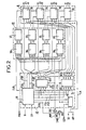
- the digital time system for connecting telephone subscribers shown in FIG. 1 is intended to allow the connection of various telecommunication devices 2 with a view to putting them into communication with identical or compatible devices via a connecting PABX 1 , possibly via telephone links 3 connecting this home exchange to other exchanges 1A, 1B of the same communication network.
- the automatic switch 1 is a digital time connection network automatic switch 4, it is placed under the control of a central processor 5, responsible in particular for establishing communications between telecommunication devices 1 via the connection network 4 .
- telecommunication devices 2 are likely to be very different, they have the characteristic - that. common to be provided to allow the exchange of signals corresponding to speech or data with identical or compatible devices via a telephone-type switching network.
- the telecommunications devices 2 are for example simple telephone sets, intercoms, sets communications systems, or answering machines designed to allow voice communications between subscribers of the same telephone communication network.
- Telecommunication devices 2 are also for example computer terminals or modems connectable to telephone lines for the purpose of data transmission, via the automatic exchange 1.
- Telecommunication devices 2 are also, for example, fax machines or terminals capable of transmitting and receiving both speech signals and data signals, such as certain terminals, called directory or certain advanced telephone sets, it being understood that '' same central office is capable of simultaneously serving 2 different telecommunication devices connected to it via lines here generally referenced L.
- the PABX 1 is capable of being connected to other PABXs, such as 1A and 1B, by wired or wireless telephone links 3, the most conventional of which are analog trunk lines, digital MIL type links or ISDN, automatic dedicated lines.
- the PABX 1 includes specialized trunks responsible for connecting the lines L of the telecommunications apparatus 2 or the telephone links 3 to its own connection network 4.
- Each specialized trunk 6 or 7 essentially comprises a connecting interface 8 or 9 respectively connected to one or more telecommunications devices 2 or to one or more telephone links 3, the devices or links connected to the same interface being identical or compatible with each other .
- Each of the attachment interfaces 8 or 9 is respectively connected, in the specialized trunk which comprises it, to an interface access 10 or 11 to the connection network 4 via an adaptation arrangement 12 or 13 for the speech or data signals and a signaling collector arrangement 14 or 15.
- An identification arrangement 16 is also provided in each trunk 6 or 7 to allow its recognition for the central processor 5, the structure and functions of the attachment interfaces and of the adaptation, signaling and identification arrangements will be specified later during the present description.
- the access interfaces 10 or 11 of the specialized trunks are connected to the switching network 4 by means of bidirectional time multiplex links LM, such as LMO, LM1, LMn, LMm in FIG. 1.
- time multiplex links LM is for example a link at 2048 Kbit / s making it possible to route thirty two telephone channels per pair of wires on a bidirectional link with two pairs of wires.
- each time multiplex link LM serves four junctions 6 or 7 which also share the thirty two time channels.
- the distribution of the time channels is for example a function of the geographical position of each trunk with respect to the three other trunks with which it shares a LM time multiplex link in the mounting unit which includes them: in this case, it is the individual positioning of each of the four connectors provided at the backplane to connect four trunks to the same time-division multiplex link LM, which determines the allocation of the time channels to each of the trunks, said connectors being chosen to be all identical for the connection of the trunks to the links LM time multiplexes, despite the differences between trunks.
- Each time multiplex link LM is responsible for transmitting all the information switched or to be switched by the connection network 4 and all the signaling associated with this information for each of the junctions 6 or 7 that it serves, said information and said signaling sharing the time channels assigned to trunk considered in each direction of transmission.
- connection network 4 consists of one or more switching matrixes to which the time multiplex links LM0 to LMn end.
- connection network 4 is constituted by an 8 ⁇ 8 type matrix making it possible to switch the time channels of eight bidirectional time multiplex links LM, such as the matrix referenced M088 from the company SGS.
- such matrices include a switching memory 17, often called speech memory, this memory receives the bytes successively supplied by the time multiplex links LM, via an input multiplexer 18, for each of the different time channels that these links behave in a first sense, says incoming.
- the various bytes received are retransmitted by the switching memory 17, in a determined order and via an output demultiplexer 19, on the second direction time channels, called outgoing, of the LM multiplex links intended for the junctions 6 or 8 responsible for them forward further.
- the byte output of the switching memory 17 is connected in parallel at the input of the output demultiplexer 19 and at the input of an exchange interface 20 allowing in particular the central processor 5 to read the bytes appearing at the output of the switching memory 17.
- the exchange interface 20 is connected to the input / output bus 21 of the central processor 5, which also connects this processor to its usual set of read and write memories 22.
- the exchange interface 20 is also connected to an input of a two-input multiplexer 23, inserted between the input of the demultiplexer 19 and the output of the switching memory 17 to which it is connected by its second input.
- the link thus established between the central processor 5 and the multiplexer 23 allows the central processor 5 to substitute a byte defined according to its needs for a byte from the switching memory in any outgoing time channel from any of the LM multiplex links. .
- the switching memory 17 is placed under the control of a control memory 24 and a time base 25 which distribute the control of the writes and leotures of bytes in this switching memory.
- the time base 25 receives a clock signal H and a synchronization signal SY from a central clock 26 of the switch which is external to the connection network 4.
- the multiplication of the clock frequency by a factor of two or multiple, for the writing and reading operations in switching memory 17 allows time for direct reading by the central processor 5 of the bytes stored, without disturbance of the reading phases of the bytes sent on the outgoing time channels of the LM time multiplex links.
- the control memory 24 is conventionally addressed in writing by the central processor 5 via the exchange interface 20 and a first addressing selector 27 and in reading by the time base 25, via this first addressing selector.
- the switching memory 17 is addressed by the control memory 24 or by the time base 25, via a second address selector 28, for its read and write operations.
- the central processor 5 has at least one peripheral equipment 68 comprising an asynchronous universal transceiver circuit 29, of the UART or USART type, intended to transmit or receive, for the central processor 5 and in the form digital, at least certain information to or from trunk 6 or 7.
- peripheral equipment 68 comprising an asynchronous universal transceiver circuit 29, of the UART or USART type, intended to transmit or receive, for the central processor 5 and in the form digital, at least certain information to or from trunk 6 or 7.
- each asynchronous transceiver circuit 29 is connected on the one hand to the input-output bus 21 of the central processor 5 on the other hand to a time multiplex link LM, such LMm, giving it access to the connection network 4, via an individual link circuit 30 •
- Each link circuit 30 ensures the formatting of bytes MIC compatible with the data transmitted in serial form by the associated asynchronous transceiver circuit 29, with a view to the transmission of these bytes on an incoming time channel of the time multiplex link LM, intended for a trunk via the connection network 4.
- Each link circuit 30 also ensures the transmission in series to the associated asynchronous transceiver circuit 29 of the bits contained in the bytes received from a trunk via an incoming time channel of the time multiplex link which draws it, the network of connection 4 and an outgoing time channel of the time multiplex link LMn.
- An identification arrangement 16 associated with the link circuit 30 allows the recognition of the peripheral equipment 68 which comprises it.
- a time multiplex link LMn also makes it possible to connect auxiliary equipment 31 of the PABX 1 to the switching network 4 of this PABX, for example for the purposes of processing the multifrequency signals possibly received from certain trunks .
- Each auxiliary equipment 31, which preferably connects to the time multiplex junction LMn like a trunk 6 or 7, is equipped for this purpose with an access interface 32, similar to the access interfaces 10 and 11, which will be specified more away with these.
- the access interface 32 is connected on the one hand to a signaling arrangement 33 intended to receive and transmit the signals coming from or intended for the automatic exchange 1 and on the other hand to a processing arrangement 34 able to convert the information received as information usable by the automatic branch exchange, if necessary, this information received being for example dialing information transmitted coded in multifrequency form.
- the auxiliaries 32 each have an identification arrangement 16 allowing them to be recognized by the central processor 5 as do the trunks 6 or 7.
- the processing arrangement 34 is indeed heard in conjunction with the signaling arrangement 33 for the purposes of its function.
- the specialized trunk shown in Figure 2 is intended to serve common telephone sets not shown, here provided four in number, individually connected by their line wires to the terminals referenced globally E1, E2, E3, E4 of four conventional line circuits subscriber 35 which in this case constitute the connection interface 8 of the trunk considered.
- Each subscriber line circuit 35 is connected to a so-called coded MIC encoder-decoder 36 via a two-wire / four-wire pass circuit 37, so as to allow coding, as a MIC sample, of the analog signals which 'it receives from the telephone set it serves and the analogue form of the speech signals constituted by a succession of regularly spaced MIC samples which are intended for it.
- the four codecs 36 of the trunk which are preferably of the cofidec type associating a filter with the codec-decoder itself, are connected in parallel to a bidirectional time multiplex link, such as LMO, or more precisely to each of the two unidirectional time multiplex links of ME transmission and MR reception of opposite direction of this LMO link.
- a bidirectional time multiplex link such as LMO
- the emission of MIC samples by the codecs 36 during the channel time intervals reserved for the trunk during the frames on the unidirectional time multiplex link ME is controlled by a circuit by a clock circuit 38 receiving signals from clock H and synchronization SY of clock 26 of the PABX 1, as well as indications POS here consisting of a two-bit word enabling it to determine the positions of the time slots allocated to the trunk which includes it.
- LMO time-division multiplex link
- the clock circuit 38 which is usually presented as a counter will not be described further since it is of structure known to those skilled in the art.
- This clock circuit 38 controls an output amplifier 39S via a link CHI connecting the codecs 36 to the transmission link DX on which they send the MIC samples, so that the junctor has a high impedance state, at its junction to said link ME during the frame time intervals reserved for the transmissions of the other junctions on this link.
- the clock circuit 38 conventionally supplies the four coded codes 36 placed under its control on the one hand with the clock signals CLK of sampling frequency 8 KHz, on the other hand with individual activation signals FSA, FSB, FSC and FSD for the frame time interval assigned to each of them.
- the clock circuit 38 specifically provides time indications making it possible, on the one hand, to send cyclic identification information from the trunk which includes it each time it is transmitted on the transmission link ME during the different frames, on the other hand the sending of signaling information by the signaling collector arrangement 14 of this trunk.
- the identification information is provided by the identification arrangement 16 of the trunk which is controlled by the clock circuit 38 and which attacks the transmission link ME upstream of the output amplifier 39S in parallel with the codecs 36.
- This identification information is provided in coded form, for example in the context of a byte referenced "lcp" transmitted during the last of the eight time intervals reserved for each of the four junctions during each frame on the transmission link.
- the "lep" byte contained in the last of the eight time intervals reserved for a trunk 6, 7, auxiliary equipment 31, or peripheral equipment 68 during a frame is systematically an identification byte.
- trunks, auxiliary or peripheral equipment each correspond to a different "lcp" identification byte which takes into account their type and level of equipment for those of them who are likely to serve a number variable of terminals 2, this information being introduced into the trunk with possibly others by an identification logic, for example wired, not shown, via a set of links referenced LCP.
- an identification byte comprising for example only bits of the same value, is generated by wiring for the unoccupied trunk positions on the transmission links ME.
- each trunk 6 or 7 includes a signaling collector arrangement 14 ensuring the bidirectional transmission of the signals, after possible adaptation, between the attachment interfaces 8 or 9 and the central processor 5, via the switching network 4 and for the purposes of operation by the PABX 1, that is to say between the subscriber line circuits 35 and the central processor 5, via the connection network 4, in the case of the trunk shown in Figure 2,
- the signaling collector arrangement 14 of this trunk 2 includes an input collector unit 40 of the multiplexer type receiving, via specific OET links, the signals provided here in the form of changes of state by the telephone sets connected to the terminals E1 to E4 of the subscriber line circuits 35 and translating these changes of states in the form of binary data transmissible over the time channels of the transmission link ME to which said input collecting unit is connected.
- the signaling collector arrangement 14 also includes an output collector unit 41 of the demultiplexer type, connected to the reception link MR downstream of an input amplifier 39E to receive the signals transmitted in digital form by the process. central unit 5, via the connection network 4.
- Activation on transmission of the input collecting unit 40 and on reception of the output collecting unit 41 is simultaneously ensured by the clock circuit 38 which provides activation signals FS1 to FS4 for this purpose during the concerned frame time intervals and bit transmit and receive clock signals over links not shown here.
- the output collector unit 41 transforms, in a manner known per se, the digital signaling information received from the central processor 5 into a state which is transmitted to the subscriber line circuits 35 by specific links generally referenced CET.
- the clock circuit 38, the signaling collector arrangement 14 and the identification arrangement 16 are integrated into the same circuit called analog terminals 42.
- the subscriber line circuits 35 constantly receive and via a set of distribution links LD, various auxiliary signals such as the alternative ringing signals AP or TO tones which they are likely to transmit on command to the telephone sets they serve.
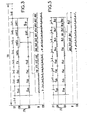
- said trunk specializing in serving analog telephone sets, has eight time channels in each of the two directions of transmission of the time multiplex link, here LMO, to the wires of which the non-illustrated connector to which it is connected connected. Knowing that the same clock defines the channel time intervals for each direction of transmission, we arrange according to a usual process so that the time channels of the same rank, therefore corresponding to the same frame time interval in both directions on the time-division multiplex link, are assigned to the same trunk, such as the time channels correspond to the time intervals referenced "i" to "i + 7" for a frame with thirty two channel time intervals in FIG. 3, on the links MR and ME in the opposite direction to the time multiplex link LMO.
- each of the time intervals referenced “i” to “i + 3" corresponds to two transmitting time channels, one in one direction on the transmission link ME and the other in the another direction on the reception link MR, information exchanged between one of the stations connected by its line wires to the jotter and another station to which it is connected via said trunk and the switching network 4.
- the distribution of the time channels, referenced fsa, fsb, fsb or fsc, to the stations connected to a trunk is preferably geographic and therefore depends on the respective position of the terminals E1, E2, E3 or E4 to which the line wires of the station in question are connected .
- the clock circuit 38 of the trunk which successively activates the coded codes 36 so as to make them each transmit a byte corresponding to a sample of the analog signal which it receives from a station, via the circuit of subscriber line 35 and the two-wire / four-wire pass circuit which serve it, and to make them each recover a sample received via the reception link MR during the interval which is individually assigned to them for each frame and that the clock circuit successively indicates to them by individual activation signals FSA to FSD transmitted on the links also bearing these references in FIG. 2 and corresponding to the time channels fsa to fsd.
- each of the time intervals referenced "i + 4" to "i + 7", in the case of the trunk shown in FIG. 2, are assigned on the reception link MR, to the transmission of commands status "cetl” to "cet4" for the benefit of the four stations connected to subscriber line circuits 35 of the trunk.
- these status commands are simple and few in number and include, for example, an "ap” command for sending the ringtone, two “ct1" and “ct2” commands for sending tones and a command “csb” of hold which is here each translate as a binary element.
- These commands “ap, ctl, ct2 and csb” are grouped into a half-byte which is transmitted with each frame in a time channel of the reception link MR assigned to the station concerned such as the time channel referenced "cet3" of the link reception MR which corresponds to the time interval "i + 5" and which is assigned here to the third station or more precisely to the third subscriber circuit 35 of the trunk 6 here taken into account in FIGS. 1 to 3.
- the status control half-byte occupies the four successive positions of binary elements "k + 4" to k + 7 ", the four positions" k “to k + 3" of the byte being fulfilled not significantly.
- Such bytes “ ⁇ et1 to cet4" corresponding to the four time channels of rank “i + 4" to “i + 7" in the frame are received by the input collecting unit 40 of the trunk activated successively by signals FS1 to FS4 of the clock circuit 40 which are transmitted by the links bearing these same references to this collecting unit. The latter then transmits by change of state on the CET links which connects it to the subscriber line circuits 35 of a trunk any order concerning the positions that these circuits individually serve.
- the time intervals referenced "i + 6" and "i + 7" are assigned, on the transmission link ME, to the transmission of a byte of observation of state "oet" of the trunk and more precisely of the four stations connected to the terminals of these subscriber line circuits 35 as well as to the transmission of the byte "lcp" of identification of the trunk and its level d 'equipment.
- the status observation byte "oet" groups together in its eight binary elements "m” to "m + 7" four observations da1 to da4 relating to the position of the earthing button provided on each of the four stations connected to the trunk considered and four observations db1 to db4 relating to the loop state of each of these four stations.
- the subscriber line circuit 35 conventionally monitors any change in loop state or of the earthing status of the station connected to its terminals and indicates the appearance of such a change via the OET links to the output collector unit 40 of the trunk which includes it. The latter modifies the binary value of the corresponding observation bit in the observation byte "oet" that it transmits during the next framing on the transmission link ME.
- identification arrangement 16 activated by the clock circuit 38 which generates the identification byte "lcp", said identification arrangement 16 possibly being able to act in cooperation with the collecting unit. outlet 40, according to a possible alternative embodiment.
- picking up an analog telephone set on call results in the trunk 6 which serves it by modifying the binary value of the loop observation bit "db", for example "db2", in the byte produced by this junctor 6 during the frame which follows the closing of the line loop caused by the stall.
- the byte "oct" transmitted by the transmission link ME of the time multiplex link LMO is then written in switching memory 17 of the switching network 4 (FIG. 1) at the address where the bytes "oct” succeed one another. generated by the junctor 6 considered during the successive frames.
- the chosen clock frequency enables the central processor 5 to read the switching memory 17 at the address where the bytes "oct” transmitted successively in the course of successive frames are replaced one after the other. trunk 6 considered, each byte being transmitted in parallel to the central processor 5 via the interface 20 and the bus 21 for analysis purposes.
- the sending of the dialing invitation tone to the extension that has made the call by picking up the handset is sent by modifying the binary value of the tone sending command, for example "ct1" of the byte transmitted, during the following frame in the time channel for example "cet2" used for sending signaling to the subscriber line circuit serving the calling station for the trunk considered.
- the modification of the binary value of the commands for sending tones is carried out by the processor 5, via the interface 20, it writes the appropriate byte in the switching memory 17 at the address allowing the subsequent sending of this byte on the time multiplex link LMO, or more precisely on its reception link MR, during the time interval "i + 6" following under the action of the control memory 24.
- the reception of the tone send command "otl" in the time channel "ect2" concerned is effected at the level of the output collecting unit 41 of the trunk 6 concerned; this unit is activated during the time interval "i + 6", it causes an order to be sent to the subscriber line circuit 35 concerned, via one of the CET links.
- the line circuit supplies the station connected to its terminals E2 with analog signals of TO tone, via the LD link concerned and via a switch not shown.
- each trunk 6 signals to the processor 5 the type of numbering used by the devices 2 and in particular the telephone sets connected to it.
- this feature is provided to the central processor 5.
- the processor 5 Upon recognition of a call by such a station, the processor 5 establishes a path through the switching network 4 between the subscriber line circuit 35 to which the station in the trunk 6 is connected and a multifrequency signaling receiver placed in auxiliary equipment position 31 in the switch 1.
- each multifrequency receiver is composed of four identical units not shown having the general structure defined for the auxiliary equipment 31 presented in FIG. 1 and it is capable of replacing a trunk in a connector due to the standardization of their H, SY, POS, MR, ME and LCP links.
- Each of the four possible units of a multifrequency receiver has an individual time channel on the reception link MR of the multiplex link LM, such as LMn, to which the receiver is connected, which allows the simultaneous processing of the multifrequency signaling bytes emanating from four separate callers, the other four time channels reserved for the receiver not being used.
- Two time channels are shared between the four units on the transmission time link ME for the sending to the processor 5 of the digits, these are each coded on four bits and are successively obtained by conversion of the multifrequency code into binary code by l processing arrangement 34 of a unit, this arrangement being a conventional code converter known per se.
- Multifrequency dialing signals transmitted on a "time channel of the subscriber line circuit 35 of a calling station up to a multi-frequency receiver unit via the switching memory 17, are successively transmitted digit by digit to the processor 5, via the switching memory 17 and in the form of successive nibbles on a time channel. They are grouped here with the quartets corresponding to another multifrequency receiver unit, active or not.
- the processor 5 comes to read the switching memory 17 via the interface 20 at the address corresponding to the signaling which it expects, the latter grouping here two nibbles relating to two different calls, one of which can be fictional. It is at the level of the multiplexer 23 that is decided under the control of the processor 5 the transfer or not of the outgoing bytes from the switching memory 17 to the output demultiplexer 19 for transmission or not, the bytes intended specifically for the processor 5 n of course not being transmitted through this output demultiplexer.
- the processor 5 has direct access in the switching memory 17 to the signaling information originating from the junctions 6 mentioned above.
- the signaling information which emanates from the junctions 7 serving connection links to other automatic exchanges when these links are of the analog trunk line type, the junctions 7 then hardly differ from the junctions 6, only their attachment interface 9 is specifically adapted for the exchange of signals by change of states or multi-frequencies specific to this type of line. Therefore this interface 9 and the trunk 7 which comprises it are not described further in so far as they do not comprise original elements compared to what is described here or to what is part of the known technique of one skilled in the art.
- the 6I trunk shown in Figure 4 is intended to serve telecommunication devices 2 for which data must be exchanged in serial form between the PABX 1 and the device by an additional line parallel to the usual telephone line, this being for example the case with intercom stations and in particular those with display, such a station being shown diagrammatically under the reference 2In.
- a pair L2 of telephone wires intended for the transmission of data in asynchronous and serial form is associated with the pair L1 of telephone wires intended for the transmission of the switched signals constituting the communications exchanged via switch 1.
- the station 2In has for this purpose an audio circuit 43 connected via a transformer 44 to line 21 and connecting to this line at least a microphone 45 and an earphone 46 in known manner.
- This audio circuit conventionally receives speech signals in analog form or possibly transcoded data that can be transmitted by the line like analog speech signals.
- the primary of the transformer 44 to which the wires of the line L1 are connected is likely to be subjected to a current signal DE applied via a current generator not shown in a circuit 47 allowing to call the processor 5 of the PABX 1 for the purpose of establishing or modifying a communication.
- the processor call circuit 47 is controlled by the control unit 48 of the station 2In conventionally organized around a microprocessor with which memories are associated, according to a conventional structure not developed here.
- the control unit 48 conventionally controls at least one keyboard 49 allowing the operation of the station 2In by the users and possibly a display 50 allowing the communication of messages, most often alphanumeric to the users.
- the control unit 48 calls the processor 5 of the automatic exchange by sending a current signal "from" on the line L1 via the call circuit 47.
- the processor 5 responds to the control unit 48 of a station intercommunication system 21 requesting via the serial link constituted by the line L2 which is connected to a transmitting and receiving interface 51 converting in parallel form the data received in series via this line in order to transmit them to the control unit 48 , this interface performs the reverse conversion for the data sent by the control unit 48 to the processor 5.
- the intercommunication station is remotely supplied, via line L2, by the trunk 6I to which it is connected, this line ends for this purpose on a supply circuit not shown, this supply circuit is placed in parallel with the transmitter-receiver interface 51 in the station.
- the 6I trunk to which the 2In station is connected is capable of serving several identical intercom stations such as 2In and 2Im here, the number of stations here being limited to four per 6I interconnector, each of these stations leading to individual equipment communication 53, such as equipment 53m and 53n.
- Each intercommunication equipment, such 53n includes a coded or cofidec 54 in series with a two-wire-four-wire pass circuit 55 the two globally referenced terminals E'n of the latter are connected to the line L1 which transmits the low analog signals frequency of communications and current signal DE.
- a detector circuit 56 monitors the appearance of the current signal DE when it is transmitted by the station 2In, it is connected for this purpose to the two terminals E'n.
- the 2In station's remote power supply is ensured by the intercommucication equipment 53 by a non-figured circuit connected to the two terminals referenced E "n, a conventional circuit-breaker protection circuit not figured protects the latter against overvoltages likely to occur by the intermediate of lines L1 and L2.
- Line L2 is also connected in parallel to a first transmitter circuit 57, here called a trunk, responsible for converting the signals received from the processor 5, via the switching network 4 and a receiving unit 61 into differential signals with a square shape transmitted. via the line L2 as well as a second transmitter 58, called a station, capable of converting the differential signals with a square shape transmitted by the station via the line L2 into unipolar rectangular pulses.
- a first transmitter circuit 57 here called a trunk
- a receiving unit 61 responsible for converting the signals received from the processor 5, via the switching network 4 and a receiving unit 61 into differential signals with a square shape transmitted.
- a second transmitter 58 called a station
- the compatible MIC pulses emitted by the transmitting circuits 58 of the intercom equipment of an intercom communi cation link 6I are gathered in a transmitting unit 59 of a common integrated circuit 60, to which the transmitting circuits are connected by individual links LSX , such LSXn.
- the transmitter unit 59 ensures the sampling of the signals received from the station transmitter circuits 58 and their coding in the form of MIC compatible bytes as well as the transmission of said bytes during the time intervals "j + 4" to j + 7 "assigned to the trunk which includes it.
- the common circuit 60 which is similar to the terminal circuit 42, also includes a receiving unit 61 connected by individual LSR links, such as LSRn, to the trunk transmitter circuits 57 belonging to the intercommunication trunk which includes it, this to recover the bytes appearing during the time intervals "d + 4" to "d + 7" allocated to this trunk for the purpose of sending the information they contain to the intercom stations after conversion.
- LSRn individual LSR links
- the receiving unit 61 is controlled in its pulse distributions by a clock circuit 62 analogous to the clock circuit 38 and receiving like the latter the clock signals H and synchronization SY as well as the indications POS allowing it to know which channel time slots that are assigned to the intercom junctor which comprises on the link LM multi- p temporal Lexe such LM1, which is connected to this interface circuit.
- the receiving unit 61 is connected to the unidirectional reception link DR of the link LM1, via an input amplifier 63 and a time-setting flip-flop 64, present but not shown for the terminal trunk shown in FIG. 2 .
- the transmitting unit 59 is controlled in its transmissions by the clock circuit 62, via an FSX link indicating the MIC compatible pulse transmission time intervals for the various intercommunication equipment of the trunk, just as the receiving unit is controlled by the clock circuit 62 via an FSW link.
- the transmitting unit 59 is connected by its output to the unidirectional transmission link DX of the time multiplex link LM1, in parallel with the coded codes 54 of the intercom equipment of the trunk, the identification arrangement 16 of this trunk and a call signal collecting circuit 65 receiving the call indications emanating from the extraction circuits 56 of the trunk.
- An output amplifier 66 placed downstream of a time-setting flip-flop 67 receives the MIC or MIC compatible signals respectively transmitted on the one hand by the codecs 54 of the intercom equipment of the trunk, on the other hand by the identification arrangement, the call signal collecting circuit and the transmitting unit, it transmits them on the unidirectional transmission link of the time multiplex link LM1 to the switching network 4, in the absence of setting command in the high impedance state of its output by the clock circuit 62 via the CHI link, when said link is temporarily assigned to another trunk.
- the identification arrangement 16 and the call signal collecting circuit 65 are selectively activated under the control of the clock circuit 62 via the FSZ and FSY links, the first of them receiving identification information "lcp "coded by wiring and supplied by the LCP link, which here comprises four wires corresponding to four bits of information and specifying the type of the trunk and its level of equipment.
- FIG. 5 makes it possible to specify the operation of an intercommunication junctor, such as 6I, in connection with the other parts of the automatic branch exchange, this junctor permanently having eight time channels on the time multiplex link LM1 which connects it to switching network 4 of the PABX 1 which includes it.
- an intercommunication junctor such as 6I
- time channels correspond to the eight time intervals referenced “j" to “j + 7" in FIG. 5.
- Each of the time intervals referenced “j” to “j + 3" corresponds to two time channels of opposite direction reserved for the bytes “fsa” to "fsd” passing through the oodecs 54 of the intercom equipment 53 of the trunk considered, each of these time intervals being assigned to a different codec for example depending on the position in the trunk of intercommunication equipment comprising this codec.
- the bytes "fsa” to "fsd” correspond to sound samples coded MIC or to data put in a form having allowed their coding MIC.
- time intervals referenced "j + 4" to "j + 7" are shared both on the transmission link DX and on the reception link DR.
- the time channel corresponding to the last time interval "j + 7" on the transmission link DX is divided into two half-channels, the first of which is reserved for the transmission of an identification quartet comprising the four bits of identification "lep" and the second of which is reserved for the transmission of quartets "ls1" corresponding to the digital data transmitted by one of the transmission circuits 58 of the trunk.
- the time channel corresponding to the time interval "j + 7" on the reception time link DR is divided into two half-channels, one of which, here the second, is reserved for the reception of quartets "ls1" corresponding to the digital data transmitted to the reception circuit 57 belonging to the same intercommunication equipment as the transmission circuit 58 considered above.
- the first half-channel of the time channel corresponding to the time interval "j + 6" on the transmission channel is reserved for a quartet "of" emanating from the extraction circuit 56 of the trunk, the four bits referenced " n “to” n + 1 "of this quartet each translate to the present state of the signal in current DE of one of the stations interconnections 21 connected to the trunk 6I.
- control unit 48 of each of the intercom stations 21 acts on the call circuit 47 which comprises it to request communication with the processor 5 of the automatic exchange 1.
- This request results in a modification of the binary state of the bit, such as "de1", assigned to the intercom equipment serving the station from which said request originates, in the quartet "of” sent on the link of DX emission during the time interval "j + 6" which follows the detection of this modification by the detector circuit 56 of the trunk concerned.
- This quartet “of” is written in switching memory 17 at the address corresponding to the time channel which transmits it, it is therefore available to processor 5 which, as we have seen, has direct read access to the switching memory.
- the processor 5 therefore has the possibility of simultaneously taking cognizance of the access requests emanating from the intercom stations 21 served by the same trunk 61 within a period corresponding at most to the duration of a frame.
- the processor 5 On receipt of an access request by an intercom station 21, the processor 5 establishes a path between the intercom equipment 53 serving this station and one of the asynchronous universal transceiver circuits 29 available to it via the link circuit 30 serving this transmitter-receiver circuit, the time multiplex link LMm to which the link circuit is connected, the connection network 4 and the time multiplex link LM1 connected to the considered intercom equipment.
- the control unit 48 sends the digital data of the concerned intercom station 2I which it wants to transmit in the form of a message composed here in succession of a binary element, said to be the start, always identical, of eight corresponding binary elements to the data to be transmitted, a parity binary element and two end of message binary elements at a speed corresponding for example to 9600 bauds.
- the message received at the station transmitter circuit 58 is converted and then transmitted to the transmitter unit 59 which samples it so as to ensure its transmission, via a channel which corresponds to a time half-channel, the rate of which is therefore thirty two kilobits per second.
- the bytes, corresponding to the message conversion and each associating a message quartet with an insignificant quartet, are transmitted during successive frames, the number of frames being for example four per message.
- the successive bytes corresponding to the same message are successively transmitted, via the connection network 4, to the link circuit 30 chosen for them by the processor 5.
- the link circuit 30 ensures the reconstitution of the message by an inverse operation to that performed by the transmitting unit 59, this inverse operation taking place under the control of the clock 26, it also eliminates the starting binary element, the two binary end elements, as well as that of parity after use of the latter for verification purposes.
- the transmission of messages to processor 5 takes place byte by byte.
- shipments from processor 5 to an intercom station 2I are transmitted via bus 21 to an asynchronous universal transceiver circuit 29 which receives them in parallel form and which constitutes a serial data stream to destination of the link circuit 30 to which said transmitter-receiver circuit is connected.
- the link circuit 30 ensures the formation of messages of constitution identical to that of those sent by the transmitting units 59 and the sampling of these messages with a view to their transmission in the form of successive bytes via a time channel. , each byte comprising a data quartet and a non-significant quartet.
- the processor 5 establishes beforehand a path between the link circuit 30 concerned and the receiving unit 61 of the interconnection trunk 6I concerned, via the multiplex link time LMm, the switching network 4 and the time multiplex link LM1 in the example proposed.
- the link circuit 30 reconstructs the message from the bytes received under the control of the clock circuit 62 of the trunk.
- the reconstituted message is then transmitted to the trunk transmitter circuit 57 which converts it so as to allow its transmission in the form of differential signals via the line L1, destined for the intercom station 2I concerned.
- the message transmitted in the form of differential signals is again reconverted in the form of unipolar binary pulses by the transmitter-receiver interface.
- the decryption of the messages received by an intercom station 2I is ensured by the processor of the control unit 48 of the station which eliminates the start, end and parity binary elements after exploitation in order to keep only the data actually coming from the processor 5 either for personal use or for transmission to the recipient unit, for example the display 50.
- junctions 6 or 7 and various auxiliary equipment 31 can be associated with the junctions and equipment described above in the proposed automatic switch 1, an adaptation being made in each case from the methods and means proposed here.
Priority Applications (1)
| Application Number | Priority Date | Filing Date | Title |
|---|---|---|---|
| AT87109799T ATE67365T1 (de) | 1986-07-10 | 1987-07-07 | System zum anschluss von telefonteilnehmern, rund um eine digitale zeitmultiplexvermittlungsanlage gestaltet. |
Applications Claiming Priority (2)
| Application Number | Priority Date | Filing Date | Title |
|---|---|---|---|
| FR8610094 | 1986-07-10 | ||
| FR8610094A FR2601541B1 (fr) | 1986-07-10 | 1986-07-10 | Systeme de rattachement d'abonnes telephoniques organise autour d'un autocommutateur temporel numerique |
Publications (2)
| Publication Number | Publication Date |
|---|---|
| EP0254920A1 true EP0254920A1 (de) | 1988-02-03 |
| EP0254920B1 EP0254920B1 (de) | 1991-09-11 |
Family
ID=9337319
Family Applications (1)
| Application Number | Title | Priority Date | Filing Date |
|---|---|---|---|
| EP87109799A Expired - Lifetime EP0254920B1 (de) | 1986-07-10 | 1987-07-07 | System zum Anschluss von Telefonteilnehmern, rund um eine digitale Zeitmultiplexvermittlungsanlage gestaltet |
Country Status (9)
| Country | Link |
|---|---|
| US (1) | US4839888A (de) |
| EP (1) | EP0254920B1 (de) |
| AT (1) | ATE67365T1 (de) |
| DE (1) | DE3772891D1 (de) |
| DK (1) | DK354387A (de) |
| ES (1) | ES2026155T3 (de) |
| FI (1) | FI873019A (de) |
| FR (1) | FR2601541B1 (de) |
| GR (1) | GR3003162T3 (de) |
Cited By (1)
| Publication number | Priority date | Publication date | Assignee | Title |
|---|---|---|---|---|
| AU749828B2 (en) * | 1997-07-04 | 2002-07-04 | Nec Corporation | Electronic switching system for creating accurate time data and its time data creating method |
Families Citing this family (9)
| Publication number | Priority date | Publication date | Assignee | Title |
|---|---|---|---|---|
| IT1188561B (it) * | 1986-03-05 | 1988-01-20 | Italtel Spa | Rete per la commutazione dei messaggi tra una pluralita' diunita' di elaborazione |
| ES2047629T3 (es) * | 1988-09-22 | 1994-03-01 | Siemens Ag | Disposicion de circuito para instalaciones de conmutacion de telecomunicaciones, especialmente instalaciones de conmutacion telefonica de multiplexacion temporal-pcm con campo de acoplamiento central y campos de acoplamiento parcial conectados. |
| FR2638307B1 (fr) * | 1988-10-21 | 1994-06-10 | Cit Alcatel | Centre de commutation pour application radiomobile |
| FR2648663B1 (fr) * | 1989-06-19 | 1994-07-22 | Alcatel Business Systems | Architecture d'installation telephonique de type prive |
| CH680101A5 (de) * | 1989-12-19 | 1992-06-15 | Alcatel Str Ag | |
| US6181707B1 (en) | 1997-04-04 | 2001-01-30 | Clear Com | Intercom system having unified control and audio data transport |
| US6901077B1 (en) * | 2000-02-23 | 2005-05-31 | Rockwell Electronic Commerce Technologies, Llc | Timeslot interchange circuit supporting PCM, ADPCM, and multiple data channel connectivity to T1 and E1 circuits |
| US8311085B2 (en) | 2009-04-14 | 2012-11-13 | Clear-Com Llc | Digital intercom network over DC-powered microphone cable |
| US9639906B2 (en) | 2013-03-12 | 2017-05-02 | Hm Electronics, Inc. | System and method for wideband audio communication with a quick service restaurant drive-through intercom |
Citations (3)
| Publication number | Priority date | Publication date | Assignee | Title |
|---|---|---|---|---|
| GB2083320A (en) * | 1980-09-02 | 1982-03-17 | Int Standard Electric Corp | Tdm telephone exchange |
| FR2503497A1 (fr) * | 1981-04-03 | 1982-10-08 | Telephonie Ind Commerciale | Systeme temporel de telecommunications |
| EP0169553A2 (de) * | 1984-07-25 | 1986-01-29 | Horst Kopetzky | Digitale Zeitmultiplex-Fernsprechanlage mit kleinen Anschlusszahlen, insbesondere Fernsprechnebenstellenanlage |
Family Cites Families (3)
| Publication number | Priority date | Publication date | Assignee | Title |
|---|---|---|---|---|
| FR2061803A5 (de) * | 1969-03-21 | 1971-06-25 | Labo Cent Telecommunicat | |
| GB2010048B (en) * | 1977-12-09 | 1982-05-06 | Hitachi Ltd | Supervisory and control system in time division switching system |
| FR2503513A1 (fr) * | 1981-04-03 | 1982-10-08 | Cit Alcatel | Autocommutateur temporel a commande repartie |
-
1986
- 1986-07-10 FR FR8610094A patent/FR2601541B1/fr not_active Expired
-
1987
- 1987-07-07 ES ES198787109799T patent/ES2026155T3/es not_active Expired - Lifetime
- 1987-07-07 EP EP87109799A patent/EP0254920B1/de not_active Expired - Lifetime
- 1987-07-07 AT AT87109799T patent/ATE67365T1/de not_active IP Right Cessation
- 1987-07-07 DE DE8787109799T patent/DE3772891D1/de not_active Expired - Lifetime
- 1987-07-08 FI FI873019A patent/FI873019A/fi not_active Application Discontinuation
- 1987-07-09 DK DK354387A patent/DK354387A/da not_active Application Discontinuation
- 1987-07-10 US US07/071,955 patent/US4839888A/en not_active Expired - Fee Related
-
1991
- 1991-11-21 GR GR91401791T patent/GR3003162T3/el unknown
Patent Citations (3)
| Publication number | Priority date | Publication date | Assignee | Title |
|---|---|---|---|---|
| GB2083320A (en) * | 1980-09-02 | 1982-03-17 | Int Standard Electric Corp | Tdm telephone exchange |
| FR2503497A1 (fr) * | 1981-04-03 | 1982-10-08 | Telephonie Ind Commerciale | Systeme temporel de telecommunications |
| EP0169553A2 (de) * | 1984-07-25 | 1986-01-29 | Horst Kopetzky | Digitale Zeitmultiplex-Fernsprechanlage mit kleinen Anschlusszahlen, insbesondere Fernsprechnebenstellenanlage |
Non-Patent Citations (2)
| Title |
|---|
| COMMUTATION & TRANSMISSION, vol. 5, no. 3, septembre 1983, pages 107-126, Issy-Les-Moulineaux, FR; P. CHARRANSOl et al.: "Présentation matérielle du MT 35: un système de commutation qui exploite les possibilités actuelle s de la technologie" * |
| IEEE JOURNAL ON SELECTED AREAS IN COMMUNICATIONS, vol. SAC-3, no. 4, juillet 1985, pages 561-568, IEEE, New York, US; A.L. JACKSON et al.: "The Harris 20-20 integrated network switch" * |
Cited By (1)
| Publication number | Priority date | Publication date | Assignee | Title |
|---|---|---|---|---|
| AU749828B2 (en) * | 1997-07-04 | 2002-07-04 | Nec Corporation | Electronic switching system for creating accurate time data and its time data creating method |
Also Published As
| Publication number | Publication date |
|---|---|
| DK354387A (da) | 1988-01-11 |
| ES2026155T3 (es) | 1992-04-16 |
| FR2601541B1 (fr) | 1988-09-23 |
| FI873019A0 (fi) | 1987-07-08 |
| FR2601541A1 (fr) | 1988-01-15 |
| US4839888A (en) | 1989-06-13 |
| ATE67365T1 (de) | 1991-09-15 |
| DK354387D0 (da) | 1987-07-09 |
| DE3772891D1 (de) | 1991-10-17 |
| GR3003162T3 (en) | 1993-02-17 |
| EP0254920B1 (de) | 1991-09-11 |
| FI873019A (fi) | 1988-01-11 |
Similar Documents
| Publication | Publication Date | Title |
|---|---|---|
| US5150357A (en) | Integrated communications system | |
| EP0374828B1 (de) | Fernsprech-Anschlussanordnung für einen Personal-Computer und eine Einrichtung dafür | |
| USRE34536E (en) | Call management system with protocol converter and port controller | |
| CA1150429A (fr) | Installation de commutation numerique a division du temps pour des lignes vehiculant la parole et des paquets de donnees | |
| US5228076A (en) | High fidelity speech encoding for telecommunications systems | |
| FR2472897A1 (fr) | Dispositif de transmission d'information de commande dans un systeme de commutation | |
| FR2472896A1 (fr) | Systeme de commutation de telecommunications | |
| EP0254920B1 (de) | System zum Anschluss von Telefonteilnehmern, rund um eine digitale Zeitmultiplexvermittlungsanlage gestaltet | |
| FR2472895A1 (fr) | Dispositif de verification de continuite pour un systeme de commutation telephonique | |
| FR2549662A1 (fr) | Procede et dispositif de transfert de communication de donnees | |
| FR2549666A1 (fr) | Procede et dispositif de pre-indication de transfert d'une communication de donnees | |
| EP0325220B1 (de) | Zeitvermittlungssystem | |
| CA2055923C (fr) | Commutateur temporel a architecture eclatee et module de raccordement pour la constitution d'un tel commutateur | |
| EP0133703A2 (de) | Digitale Ortsvermittlungsanlage für Teilnehmeranschlüsse | |
| FR2635246A1 (fr) | Systeme telephonique numerique | |
| FR2474261A1 (fr) | Systeme de transmission numerique pour telecopieur | |
| EP0141956A1 (de) | Anordnung zur Übertragung und Verarbeitung von Daten oder Signalisierungskanälen von einer Gruppe Multiplex-Leitungen | |
| EP0403998B1 (de) | Aufbau einer Fernprechnebenstellenanlage | |
| EP0610106B1 (de) | Signalierungsverarbeitungssystem für gemeinsame Unterstützung der Durchschaltebetriebsart in einer Telekommunikationsanlage | |
| EP0530098B1 (de) | Verfahren und Anordnung für Nachrichtenübertragung zwischen Geräten einer Kommunikationsanlage | |
| CA1066794A (fr) | Concentrateur telephonique | |
| US20010033566A1 (en) | Methods and apparatus for providing telephonic communication services | |
| EP0889670B1 (de) | Kommunikationsverfahren zwischen Fernsprechnebenstellenanlagen verbunden mit einem dienstintegrierenden Digitalnetz | |
| EP0486864B1 (de) | Hauptendstelle für ein dienstintegrierendes Digitalnetz | |
| FR2669491A1 (fr) | Agencement de raccordement d'un terminal analogique a un reseau numerique a integration de services et adaptateur pour un tel agencement. |
Legal Events
| Date | Code | Title | Description |
|---|---|---|---|
| PUAI | Public reference made under article 153(3) epc to a published international application that has entered the european phase |
Free format text: ORIGINAL CODE: 0009012 |
|
| AK | Designated contracting states |
Kind code of ref document: A1 Designated state(s): AT BE CH DE ES FR GB GR IT LI LU NL SE |
|
| RAP1 | Party data changed (applicant data changed or rights of an application transferred) |
Owner name: TELIC ALCATEL |
|
| 17P | Request for examination filed |
Effective date: 19880803 |
|
| RAP1 | Party data changed (applicant data changed or rights of an application transferred) |
Owner name: ALCATEL BUSINESS SYSTEMS |
|
| 17Q | First examination report despatched |
Effective date: 19901025 |
|
| GRAA | (expected) grant |
Free format text: ORIGINAL CODE: 0009210 |
|
| AK | Designated contracting states |
Kind code of ref document: B1 Designated state(s): AT BE CH DE ES FR GB GR IT LI LU NL SE |
|
| REF | Corresponds to: |
Ref document number: 67365 Country of ref document: AT Date of ref document: 19910915 Kind code of ref document: T |
|
| REF | Corresponds to: |
Ref document number: 3772891 Country of ref document: DE Date of ref document: 19911017 |
|
| GBT | Gb: translation of ep patent filed (gb section 77(6)(a)/1977) | ||
| ITF | It: translation for a ep patent filed |
Owner name: JACOBACCI & PERANI S.P.A. |
|
| REG | Reference to a national code |
Ref country code: ES Ref legal event code: FG2A Ref document number: 2026155 Country of ref document: ES Kind code of ref document: T3 |
|
| PLBE | No opposition filed within time limit |
Free format text: ORIGINAL CODE: 0009261 |
|
| STAA | Information on the status of an ep patent application or granted ep patent |
Free format text: STATUS: NO OPPOSITION FILED WITHIN TIME LIMIT |
|
| 26N | No opposition filed | ||
| REG | Reference to a national code |
Ref country code: GR Ref legal event code: FG4A Free format text: 3003162 |
|
| PGFP | Annual fee paid to national office [announced via postgrant information from national office to epo] |
Ref country code: ES Payment date: 19930518 Year of fee payment: 7 |
|
| PGFP | Annual fee paid to national office [announced via postgrant information from national office to epo] |
Ref country code: DE Payment date: 19930519 Year of fee payment: 7 Ref country code: CH Payment date: 19930519 Year of fee payment: 7 |
|
| PGFP | Annual fee paid to national office [announced via postgrant information from national office to epo] |
Ref country code: SE Payment date: 19930521 Year of fee payment: 7 |
|
| PGFP | Annual fee paid to national office [announced via postgrant information from national office to epo] |
Ref country code: GB Payment date: 19930526 Year of fee payment: 7 |
|
| PGFP | Annual fee paid to national office [announced via postgrant information from national office to epo] |
Ref country code: FR Payment date: 19930527 Year of fee payment: 7 |
|
| PGFP | Annual fee paid to national office [announced via postgrant information from national office to epo] |
Ref country code: GR Payment date: 19930528 Year of fee payment: 7 |
|
| PGFP | Annual fee paid to national office [announced via postgrant information from national office to epo] |
Ref country code: BE Payment date: 19930616 Year of fee payment: 7 |
|
| PGFP | Annual fee paid to national office [announced via postgrant information from national office to epo] |
Ref country code: LU Payment date: 19930701 Year of fee payment: 7 |
|
| PGFP | Annual fee paid to national office [announced via postgrant information from national office to epo] |
Ref country code: AT Payment date: 19930730 Year of fee payment: 7 |
|
| PGFP | Annual fee paid to national office [announced via postgrant information from national office to epo] |
Ref country code: NL Payment date: 19930731 Year of fee payment: 7 |
|
| EPTA | Lu: last paid annual fee | ||
| PG25 | Lapsed in a contracting state [announced via postgrant information from national office to epo] |
Ref country code: LU Free format text: LAPSE BECAUSE OF NON-PAYMENT OF DUE FEES Effective date: 19940707 Ref country code: GB Effective date: 19940707 Ref country code: AT Effective date: 19940707 |
|
| PG25 | Lapsed in a contracting state [announced via postgrant information from national office to epo] |
Ref country code: SE Effective date: 19940708 Ref country code: ES Free format text: LAPSE BECAUSE OF THE APPLICANT RENOUNCES Effective date: 19940708 |
|
| PG25 | Lapsed in a contracting state [announced via postgrant information from national office to epo] |
Ref country code: LI Effective date: 19940731 Ref country code: CH Effective date: 19940731 Ref country code: BE Effective date: 19940731 |
|
| BERE | Be: lapsed |
Owner name: ALCATEL BUSINESS SYSTEMS Effective date: 19940731 |
|
| EUG | Se: european patent has lapsed |
Ref document number: 87109799.4 Effective date: 19950210 |
|
| PG25 | Lapsed in a contracting state [announced via postgrant information from national office to epo] |
Ref country code: GR Free format text: THE PATENT HAS BEEN ANNULLED BY A DECISION OF A NATIONAL AUTHORITY Effective date: 19950131 |
|
| PG25 | Lapsed in a contracting state [announced via postgrant information from national office to epo] |
Ref country code: NL Effective date: 19950201 |
|
| GBPC | Gb: european patent ceased through non-payment of renewal fee |
Effective date: 19940707 |
|
| NLV4 | Nl: lapsed or anulled due to non-payment of the annual fee | ||
| PG25 | Lapsed in a contracting state [announced via postgrant information from national office to epo] |
Ref country code: FR Effective date: 19950331 |
|
| REG | Reference to a national code |
Ref country code: CH Ref legal event code: PL |
|
| PG25 | Lapsed in a contracting state [announced via postgrant information from national office to epo] |
Ref country code: DE Effective date: 19950401 |
|
| EUG | Se: european patent has lapsed |
Ref document number: 87109799.4 |
|
| REG | Reference to a national code |
Ref country code: GR Ref legal event code: MM2A Free format text: 3003162 |
|
| REG | Reference to a national code |
Ref country code: FR Ref legal event code: ST |
|
| REG | Reference to a national code |
Ref country code: ES Ref legal event code: FD2A Effective date: 19991007 |
|
| PG25 | Lapsed in a contracting state [announced via postgrant information from national office to epo] |
Ref country code: IT Free format text: LAPSE BECAUSE OF NON-PAYMENT OF DUE FEES;WARNING: LAPSES OF ITALIAN PATENTS WITH EFFECTIVE DATE BEFORE 2007 MAY HAVE OCCURRED AT ANY TIME BEFORE 2007. THE CORRECT EFFECTIVE DATE MAY BE DIFFERENT FROM THE ONE RECORDED. Effective date: 20050707 |