EP0254579A2 - Hydraulically operated continuously variable transmission - Google Patents
Hydraulically operated continuously variable transmission Download PDFInfo
- Publication number
- EP0254579A2 EP0254579A2 EP87306540A EP87306540A EP0254579A2 EP 0254579 A2 EP0254579 A2 EP 0254579A2 EP 87306540 A EP87306540 A EP 87306540A EP 87306540 A EP87306540 A EP 87306540A EP 0254579 A2 EP0254579 A2 EP 0254579A2
- Authority
- EP
- European Patent Office
- Prior art keywords
- motor
- pump
- hydraulic
- cylinder
- shaft
- Prior art date
- Legal status (The legal status is an assumption and is not a legal conclusion. Google has not performed a legal analysis and makes no representation as to the accuracy of the status listed.)
- Granted
Links
- 230000005540 biological transmission Effects 0.000 title claims abstract description 80
- 230000007246 mechanism Effects 0.000 claims abstract description 18
- 230000008859 change Effects 0.000 claims abstract description 6
- 238000006073 displacement reaction Methods 0.000 claims abstract description 6
- 230000033001 locomotion Effects 0.000 claims description 27
- 230000004044 response Effects 0.000 claims description 7
- 230000000295 complement effect Effects 0.000 claims description 2
- 230000008878 coupling Effects 0.000 claims description 2
- 238000010168 coupling process Methods 0.000 claims description 2
- 238000005859 coupling reaction Methods 0.000 claims description 2
- 238000004891 communication Methods 0.000 description 17
- 238000009826 distribution Methods 0.000 description 17
- 230000002093 peripheral effect Effects 0.000 description 17
- 230000001276 controlling effect Effects 0.000 description 11
- 230000006835 compression Effects 0.000 description 7
- 238000007906 compression Methods 0.000 description 7
- 230000007935 neutral effect Effects 0.000 description 5
- 239000012530 fluid Substances 0.000 description 4
- 230000001133 acceleration Effects 0.000 description 3
- 239000013256 coordination polymer Substances 0.000 description 3
- 238000010586 diagram Methods 0.000 description 3
- 238000001514 detection method Methods 0.000 description 2
- 239000000446 fuel Substances 0.000 description 2
- 230000001105 regulatory effect Effects 0.000 description 2
- 230000001174 ascending effect Effects 0.000 description 1
- 238000010276 construction Methods 0.000 description 1
- 239000000498 cooling water Substances 0.000 description 1
- 230000007423 decrease Effects 0.000 description 1
- 230000000881 depressing effect Effects 0.000 description 1
- 230000000994 depressogenic effect Effects 0.000 description 1
- 238000007599 discharging Methods 0.000 description 1
- 230000000694 effects Effects 0.000 description 1
- 239000011796 hollow space material Substances 0.000 description 1
- 230000004048 modification Effects 0.000 description 1
- 238000012986 modification Methods 0.000 description 1
- 230000009467 reduction Effects 0.000 description 1
Images


Classifications
-
- F—MECHANICAL ENGINEERING; LIGHTING; HEATING; WEAPONS; BLASTING
- F16—ENGINEERING ELEMENTS AND UNITS; GENERAL MEASURES FOR PRODUCING AND MAINTAINING EFFECTIVE FUNCTIONING OF MACHINES OR INSTALLATIONS; THERMAL INSULATION IN GENERAL
- F16H—GEARING
- F16H61/00—Control functions within control units of change-speed- or reversing-gearings for conveying rotary motion ; Control of exclusively fluid gearing, friction gearing, gearings with endless flexible members or other particular types of gearing
- F16H61/38—Control of exclusively fluid gearing
- F16H61/40—Control of exclusively fluid gearing hydrostatic
- F16H61/4043—Control of a bypass valve
-
- F—MECHANICAL ENGINEERING; LIGHTING; HEATING; WEAPONS; BLASTING
- F16—ENGINEERING ELEMENTS AND UNITS; GENERAL MEASURES FOR PRODUCING AND MAINTAINING EFFECTIVE FUNCTIONING OF MACHINES OR INSTALLATIONS; THERMAL INSULATION IN GENERAL
- F16H—GEARING
- F16H61/00—Control functions within control units of change-speed- or reversing-gearings for conveying rotary motion ; Control of exclusively fluid gearing, friction gearing, gearings with endless flexible members or other particular types of gearing
- F16H61/38—Control of exclusively fluid gearing
- F16H61/40—Control of exclusively fluid gearing hydrostatic
- F16H61/46—Automatic regulation in accordance with output requirements
-
- F—MECHANICAL ENGINEERING; LIGHTING; HEATING; WEAPONS; BLASTING
- F16—ENGINEERING ELEMENTS AND UNITS; GENERAL MEASURES FOR PRODUCING AND MAINTAINING EFFECTIVE FUNCTIONING OF MACHINES OR INSTALLATIONS; THERMAL INSULATION IN GENERAL
- F16H—GEARING
- F16H61/00—Control functions within control units of change-speed- or reversing-gearings for conveying rotary motion ; Control of exclusively fluid gearing, friction gearing, gearings with endless flexible members or other particular types of gearing
- F16H61/38—Control of exclusively fluid gearing
- F16H61/40—Control of exclusively fluid gearing hydrostatic
- F16H61/42—Control of exclusively fluid gearing hydrostatic involving adjustment of a pump or motor with adjustable output or capacity
- F16H61/421—Motor capacity control by electro-hydraulic control means, e.g. using solenoid valves
Definitions
- the present invention relates to a hydraulically operated continuously variable transmission, and more particularly to a hydraulically operated continuously variable transmission including a hydraulic pump coupled to an input shaft and a hydraulic motor coupled to an output shaft, the hydraulic pump and the hydraulic motor being interconnected by a hydraulic circuit.
- a hydraulically operated continuously variable transmission for use in an automobile, including an input shaft, a hydraulic pump having a pump cylinder coupled to the input shaft and a plurality of pump plungers disposed in the pump cylinder in an annular pattern around an axis of rotation of the pump cylinder, the hydraulic pump having an outlet port, an output shaft, a hydraulic motor having a motor cylinder coupled to the output shaft and a plurality of motor plungers disposed in said motor cylinder in an annular pattern around an axis of rotation of the motor cylinder, the hydraulic motor having an inlet port, a closed hydraulic circuit interconnecting the hydraulic pump and the hydraulic motor, a pump swash plate for reciprocally moving the pump plungers, a tiltable motor swash plate for rotating the motor cylinder in response to reciprocating movement of the pump plungers, the tiltable motor swash plate being tiltable through a continuously variable angle for continuously adjusting the stroke of reciprocating movement of the motor plungers.
- such a continuously variable transmission is controlled such that the transmission ratio will be l : l while minimizing or eliminating the angle of inclination of the motor swash plate.
- the pump plungers By breaking the hydraulic circuit which interconnects the outlet port of the hydraulic pump and the inlet port of the hydraulic motor, the pump plungers can be locked in the pump cylinder to drive the motor cylinder mechanically through the pump swash plate. With the hydraulic motor and pump thus mechanically locked, the oil pressure discharged by the hydraulic pump is prevented from acting on the motor plungers to reduce the thrust load on the motor swash plate and also to reduce oil leakage from between the motor plungers and the motor cylinder.
- a hydraulically operated continuously variable transmission to have a passage capable of communication between the outlet and inlet ports of the hydraulic pump and also to have a clutch valve for varying the cross-sectional area of the passage to change the amount of power transmitted between the hydraulic pump and the hydraulic motor thereby to control power transmission between the input and output shafts.
- Japanese Laid-Open Patent Publication No. 54-l34252 discloses a common valve for closing and opening the outlet port of the hydraulic pump and for regulating the amount of oil flow through the passage between the outlet and inlet ports of the hydraulic pump.
- the outlet port of the hydraulic pump is selectively closed and opened and the clutch valve is continuously operated or under analog control, delicate clutch control could not be achieved if the outlet port of the hydraulic pump and the clutch valve were controlled by a single actuator.
- Japanese Patent Publication No. 56-50l42 discloses an arrangement for making and breaking the hydraulic circuit by providing a piston rod which can break the hydraulic circuit and applying a hydraulic pressure to the piston rod to break the hydraulic circuit.
- the hydraulic circuit is made under the resiliency of a return spring, which should be capable of producing a relatively large spring force in order to make the hydraulic circuit reliably.
- An actuator employed for moving the piston rod to breaking the hydraulic circuit against the force of the return spring should therefore be capable of applying a large force and needs to be large in size.
- the disclosed arrangement is not preferable for this reason.
- One solution is to use a hydraulic servomotor for operating a device to make and break the hydraulic circuit with a relatively small force, as disclosed in Japanese Laid-Open Patent Publication No. 54-l34253.
- a valve for making and breaking the hydraulic circuit is operated by a pilot valve which is also governed by a spring force. In order to ensure reliable operation, therefore, a large spring force must be established, and the resulting system is large in size.
- the device for making and breaking the hydraulic circuit is subjected to hunting, and smooth running of the vehicle may not be achieved.
- a hydraulically operated continuously variable transmission comprising an input shaft, a hydraulic pump coupled to the input shaft and having inlet and outlet ports, an output shaft, a variable-displacement hydraulic motor coupled to the output shaft, a closed hydraulic circuit interconnecting the hydraulic pump and the hydraulic motor and including a passage connecting the inlet and outlet ports of the hydraulic pump, a servomotor for making and breaking the hydraulic circuit respectively by opening and closing the outlet port, a clutch valve for continuously varying the cross-sectional area of the passage to change the amount of power transmitted between the hydraulic pump and the hydraulic motor, and a control system for independently controlling the servomotor and the clutch valve, the control system being arranged to hold the servomotor in a position to open the outlet port when the clutch valve is opened beyond a prescribed degree.
- a hydraulically operated continuously variable transmission comprising an input shaft, a hydraulic pump having a pump cylinder coupled to the input shaft and a plurality of pump plungers disposed in the pump cylinder in an annular pattern around an axis of rotation of the pump cylinder, the hydraulic pump having an outlet port, an output shaft, a hydraulic motor having a motor cylinder coupled to the output shaft and a plurality of motor plungers disposed in said motor cylinder in an annular pattern around an axis of rotation of the motor cylinder, the hydraulic motor having an inlet port, a closed hydraulic circuit interconnecting the hydraulic pump and the hydraulic motor, a pump swash plate for reciprocally moving the pump plungers, a tiltable motor swash plate for rotating the motor cylinder in response to reciprocating movement of the pump plungers, the tiltable motor swash plate being tiltable through a continuously variable angle for continuously adjusting the stroke of reciprocating movement of the motor plungers, a first hydraulic servomotor operable by a first pilot
- a hydraulically operated continuously variable transmission comprising an input shaft, a hydraulic pump having a pump cylinder coupled to the input shaft and a plurality of pump plungers disposed in the pump cylinder in an annular pattern around an axis of rotation of the pump cylinder, the hydraulic pump having an outlet port, an output shaft, a hydraulic motor having a motor cylinder coupled to the output shaft and a plurality of motor plungers disposed in said motor cylinder in an annular pattern around an axis of rotation of the motor cylinder, the hydraulic motor having an inlet port, a closed hydraulic circuit interconnecting the hydraulic pump and the hydraulic motor, a pump swash plate for reciprocally moving the pump plungers, a tiltable motor swash plate for rotating the motor cylinder in response to reciprocating movement of the pump plungers, the tiltable motor swash plate being tiltable through a continuously variable angle for continuously adjusting the stroke of reciprocating movement of the motor plungers, detector means for detecting an operating condition of an engine which drives the input
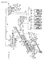
- FIG. l shows a hydraulically operated continuously variable transmission according to the present invention, the transmission basically comprising a hydraulic pump P and a hydraulic motor M housed in a transmission case l composed of a pair of longitudinally separated case members la, lb.
- the hydraulic pump P has a pump cylinder 4 splined to an end 3 of an input shaft 2, a plurality of cylinder holes or bore 5 defined in the pump cylinder 4 in a circular pattern around and concentric with the input shaft 2 and extending parallel to the input shaft 2, and a plurality of pump plungers 6 slidably fitted respectively in the cylinder holes 5.
- the hydraulic pump P can be driven by the power of an engine (not shown) which is transmitted through a flywheel 7 coupled to the opposite end of the input shaft 2.
- the hydraulic motor M has a motor cylinder 8 disposed in surrounding relation to the pump cylinder 4, a plurality of cylinder holes or bore 9 defined in the motor cylinder 8 in a circular pattern around and concentric with the input shaft 2 and extending parallel to the input shaft 2, and a plurality of motor plungers l0 slidably fitted respectively in the cylinder holes 9.
- the hydraulic motor M is rotatable relatively to the pump cylinder 4 in concentric relation thereto.
- the motor cylinder 8 has axially opposite ends on which a pair of support shafts lla, llb is disposed, respectively.
- the support shaft lla is rotatably supported on the axial end wall of the case member lb by means of a ball bearing l2
- the support shaft llb is rotatably supported on the axial end wall of the case member la by means of a needle bearing l3.
- the ball bearing l2 has an inner race l2a and an outer race l2b.
- the support shaft lla has an outer end projecting beyond the inner race l2a and on which a stop ring l4 is mounted.
- Another stop ring l5 is mounted on an outer peripheral surface of the outer race l2b near an outer end thereof, and is received in an annular recess l6 defined in an outer surface of the axial end wall of the case member lb.
- a holder plate l7 held against an outer end surface of the outer race l2b is fixed by bolts l8 to the axial end wall of the case member lb. The ball bearing l2 and the support shaft lla are thus fixedly mounted on the case member lb against axial movement.
- the other support shaft llb has an integral gear l9 meshing with an idler gear 20 for transmitting output power of the hydraulic motor M therethrough to a differential gear mechanism 2l.
- a pump swash plate 22 inclined at an angle to the pump plungers 6 is fixedly disposed radially inwardly of the motor cylinder 8.
- An annular pump shoe 23 is rotatably slidably supported on an inclined surface of the pump swash plate 22.
- Each of the pump plungers 6 has a bottomed hole 24 opening toward the pump swash plate 22.
- a connecting rod 25 is inserted in each pump plunger 6 and pivotally movable with respect to the pump plunger 6 by means of a ball joint 26a on the inner end of the connecting rod 25.
- the connecting rod 25 projects out of the corresponding pump plunger 6 from the bottomed hole 24, and is pivotally movable with respect to the pump shoe 23 by means of a ball joint 26b on the outer projecting end of the connecting rod 25.
- the annular pump shoe 23 has its outer peripheral surface supported in the motor cylinder 8 by a needle bearing 27.
- the annular pump shoe 23 has an annular step 23a defined in its inner peripheral surface facing the pump plungers 6.
- a presser ring 28 riding in the annular step 23a presses the pump shoe 23 toward the pump swash plate 22 under the resiliency of a compression coil spring 30 disposed under compression around the input shaft 2 and acting on a spring holder 29 held against the presser ring 28.
- the spring holder 29 is slidably fitted over splines 3l on the input shaft 2, and has a partly spherical surface contacting a complementary partly spherical surface of the presser ring 28. Therefore, the spring holder 29 is neatly held against the presser ring 28 for transmitting the resilient force from the spring 30 to the presser ring 28 irrespective of how the spring holder 29 and the presser ring 28 are relatively positioned.
- the pump shoe 23 can be slidingly rotated in a fixed position on the pump swash plate 22 at all times.
- Bevel gears 32, 33 which have the same number of teeth, are fixed respectively to the confronting surfaces of the pump shoe 23 and the pump cylinder 4 and are held in mesh with each other.
- the pump shoe 23 is rotated in synchronism with the pump cylinder 4 through the meshing bevel gears 32, 33.
- those pump plungers 6 which run along an ascending side of the inclined surface of the pump swash plate 22 are moved in a discharge stroke by the pump swash plate 22, the pump shoe which travel along a descending side of the inclined surface of the pump swash plate 22 are moved in a suction stroke.
- Substantially one half of the pump plungers 6 are always in the discharge stroke, and hence corresponding one half of the pump shoe 23 is pressed against the pump swash plate 22 by the connecting rods 25 under a high hydraulic pressure developed in oil chambers defined in the pump cylinder 4 behind the pump plungers 6.
- the other half of the pump shoe 23 is also subjected to the same high hydraulic pressure. Accordingly, the entire sliding surface of the pump shoe 23 is pressed against the pump swash plate 22 at all times, and remains closely in contact with the pump swash plate 22 without the danger of being lifted off even when an abrupt pressure drop is developed for some reason in oil chambers behind those pump plungers 6 which operate in the suction stroke.
- the pump shoe 23 has hydraulic pockets 34 defined in its surface held against the pump swash plate 22 and positioned in alignment with the respective connecting rods 25.
- the hydraulic pockets 34 communicate with the respective oil chambers in the pump cylinder 4 through oil holes 35 defined in the pump plungers 6, oil holes 36 defined in the connecting rods 25, and oil holes 37 defined in the pump shoe 23. While the pump cylinder 4 is in operation, therefore, oil under pressure in the pump cylinder 4 is supplied to the hydraulic pockets 34 to apply a hydraulic pressure to the pump shoe 23 in a direction to bear the thrust force imposed by the pump plungers 6 on the pump shoe 23. Therefore, the oil supplied to the hydraulic pockets 34 serves to reduce the pressure under which the pump shoe 23 contacts the pump swash plate 22, and also to lubricate the mutually sliding surfaces of the pump shoe 23 and the pump swash plate 22.
- a motor swash plate 38 is tiltably supported in the transmission case l by means of a pair of trunnions 39 projecting from opposite sides of the motor swash plate 38, which is held in confronting relation to the motor plungers l0.
- the motor swash plate 38 has an inclined surface on which there is slidably disposed a motor shoe 40 that is pivotally coupled to ball joints l0a on the outer ends of the motor plungers l0.
- Each of the motor plungers l0 reciprocally moves in expansion and compression strokes while rotating the motor cylinder 8.
- the stroke of the motor plungers l0 can be adjusted from zero to a maximum level by varying the angle of inclination of the motor swash plate 38 from a vertical position (shown by the two-dot-dash lines) in which the motor swash plate 38 lies perpendicularly to the motor plungers l0 to a most inclined position (shown by the solid lines), as described later on.
- the motor cylinder 8 comprises axially separate first through fourth members or segments 8a through 8d.
- the first member 8a includes the support shaft llb and accommodates the pump swash plate 22.
- the second member 8b has guide holes 4l in the cylinder holes 9, in which the motor plungers l0 are slidably guided, respectively.
- the third and fourth members 8c, 8d have oil chambers 42 in the cylinder holes 9, the oil chambers 42 being slightly larger in diameter than the guide holes 4l.
- the third member 8c serves as a distribution member 43 having oil passages leading to the cylinder holes 5, 9, and the fourth member 8d includes the suppoer shaft lla.
- the first member 8a has an integral joint flange 44 on its end facing the second member 8b.
- the joint flange 44 is fitted relatively tightly in a positioning hole 45 defined in the end face of the second member 8b that confronts the joint flange 44.
- the joint flange 44 is fastened to the second member 8b by means of a plurality of bolts 46.
- the second, third, and fourth members 8b, 8c, 8d are relatively positioned by knock pins 47 fitted in positioning holes defined in their confronting end faces, and are firmly coupled together by means of a plurality of bolts 48.
- the input shaft 2 has an outer end portion rotatably supported centrally in the support shaft llb of the motor cylinder 8 by a needle bearing 49, and an inner end portion rotatably supported centrally in the distribution member 43 by a needle bearing 50.
- the spring 30 is disposed under compression between the pump cylinder 4 and the spring holder 29 for pressing the pump cylinder 4 against the distribution member 43 to prevent oil from leaking from the sliding surfaces of the pump cylinder 4 and the distribution member 43.
- the resilient force of the spring 30 is also effective in supporting the spring holder 29, the presser ring 28, the pump shoe 23, and the pump swash plate 22 firmly in the motor cylinder 8, as described above.
- the support shaft lla is of a hollow structure in which a fixed shaft 5l is centrally inserted.
- a distribution ring 52 is fitted over the inner end of the fixed shaft 5l in a fluid-tight manner through an O-ring therebetween.
- the distribution ring 52 has an axial end face held eccentrically in sliding contact with the distribution member 43.
- the fourth member 8d of the motor cylinder 8 has an interior hollow space 53 which is divided by the distribution ring 52 into an inner oil chamber 53a and an outer oil chamber 53b.
- the distribution member 43 has an outlet port 54 and an inlet port 55.
- the outlet port 54 provides fluid communication between the cylinder holes 5 that receive the pump plungers 6 operating in the discharge stroke and the inner oil chamber 53a.
- the inlet port 55 provides fluid communication between the cylinder holes 5 that receive the pump plungers 6 operating in the suction stroke and the outer oil chamber 53b.
- the distribution member 43 also has a number of communication ports 56 defined therein and through which the cylinder holes 9 of the motor cylinder 8 communicate with the interior space 53 in the fourth member 8d.
- a closed hydraulic circuit is formed between the hyraulic pump P and the hydraulic motor M through the distribution member 43 and the distribution ring 52.
- high-pressure working oil discharged by the pump plungers 6 in the discharge stroke flows from the outlet port 54, the inner oil chamber 53a, and the communication ports 56 communicating with the inner oil chamber 53a into the cylinder holes 9 receiving the motor plungers l0 which are in the expansion stroke, thereby imposing a thrust on these motor plungers l0.
- Working oil discharged by the motor plungers l0 operating in the compression stroke flows through the communication ports 56 communicating with the outer oil chamber 53b and the inlet port 55 into the cylinder holes 5 receiving the pump plungers 6 in the suction stroke.
- the motor cylinder 8 Upon such circulation of the working oil, the motor cylinder 8 is driven by the sum of the reactive torque applied by the pump plungers 6 in the discharge stroke to the motor cylinder 8 through the pump swash plate 22 and the reactive torque received by the motor plungers l0 in the expansion stroke from the motor swash plate 38.
- the transmission ratio can be varied from l to a desired value by varying the displacement of the hydraulic motor M from zero to a certain value.
- the transmission ratio can continuously be adjusted from l to a certain value by tilting the motor swash plate 38 from the vertical position to a ceratin inclined position.
- a hydraulic ratio-changing servomotor Sl, or a first servomotor, for tilting the motor swash plate 38 is disposed in an upper portion of the transmission case l.
- the ratio-changing servomotor Sl comprises a servo cylinder 58 fixed to the transmission case l, a servo piston 6l movably disposed in the servo cylinder 58 and dividing the interior space of the servo cylinder 58 into a lefthand oil chamber 59 and a righthand oil chamber 60, a piston rod 62 integral with the servo piston 6l, and a rod-shaped first pilot valve 64 slidably fitted in a valve hole 63 defined in the piston rod 62 and extending from an end face of the servo piston 6l.
- the piston rod 6 integral with the servo piston 6l extends through the servo cylinder 58 and has an end projecting into the transmission case l.
- the projecting end of the piston rod 62 is coupled to the motor swash plate 38 through a connector 65 and pivot pins.
- the first pilot valve 64 has on its distal end a land 64a intimately fitted in the valve hole 63 and also has a pair of diametrically opposite recesses 64b defined behind the land 64a and extending over a certain axial dimension.
- a retaining ring 66 is securely fitted over the first pilot valve 64 behind the recess 64b.
- the retaining ring 66 is engageable with a retaining ring 67 fixed to the inner peripheral surface of the servo piston 6l to prevent the first pilot valve 64 from being detached from the piston rod 62.
- the piston rod 62 and the servo piston 6l have a lower discharge passage 68 defined therein for communicating the righthand oil chamber 60 through the valve hole 63 with an oil tank (not shown) upon rightward movement of the first pilot valve 64, and an upper communication passage 69 defined therein for communicating the righthand oil chamber 60 with the lefthand oil chamber 59 upon leftward movement of the first pilot valve 64.
- the lefthand oil chamber 59 of the servo cylinder 58 communicates with the interior space 53 of the fourth member 8d through an oil passage 70 defined in a peripheral wall of the servo cylinder 58 and an oil passage 7l defined in the holder plate l7. Therefore, the lefthand oil chamber 59 can be supplied with oil under pressure from the hydraulic pump P.
- the land 64a opens the communication passage 69 into the righthand oil chamber 60 and closes the discharge passage 68, as shown in FIG. l. Therefore, the oil under pressure from the hydraulic pump P acts in both the oil chambers 59, 60, whereupon the servo piston 6l is moved to the left due to the difference in pressure-bearing areas of these oil chambers.
- the servo piston 6l is operated in amplified movement by following the movement of the first pilot valve 64 under the working oil pressure from the interior space 53.
- the motor swash plate 38 can continuously be angularly shifted or adjusted from the most inclined position indicated by the solid lines in FIG. l where the transmission ratio is maximum to the least inclined position indicated by the imaginary (two-dot-and-dash) lines where the transmission ratio is minimum.
- the outer end of the first pilot valve 64 projecting through the holder plate l7 is coupled to a first link arm 72 connected to a cam mechanism Cl, the first link arm 72 being remotely controlled by a control signal, as described later on.
- a cylindrical bearing 74 is coupled to the outer peripheral surface of the fixed shaft 5l through splines 73 having relatively large dimensional tolerances in the radial direction.
- the bearing 74 has its outer peripheral surface slightly spaced from the inner peripheral surface of the support shaft lla. This spacing between the bearing 74 and the support shaft lla is uniformized by an film of working oil throughout the entire circumference of the bearing 74 so that the bearing 74 is floatingly supported in the support shaft lla.
- the fixed shaft 5l has an annular ridge 75 projecting radially outwardly and extending circumferentially in a position confronting an axially inner end of the bearing 74.
- the bearing 74 is limited in its axial movement between the annular ridge 75 and an inner surface of the holder plate l7 fixed to the outer end surface of the transmission case member lb.
- annular groove 76 is defined in the outer peripheral surface of the fixed shaft 5l.
- the annular groove 76 receives therein an O-ring 77 and a backup ring 78 both serving as seal members.
- the fixed shaft 5l is of a hollow construction having a peripheral wall having radial connecting ports 79a, 79b through which the inner and outer oil chambers 53a, 53b communicate with each other.
- a cylindrical clutch valve 80 is fitted in the interior space of the fixed shaft 5l for selectively opening and closing the ports 79a, 79b.
- the clutch valve 80 serves as a clutch for selectively connecting and disconnecting the hydraulic pump P and the hydraulic motor M.
- the clutch valve 80 is positioned by a radial needle bearing 8l radially with respect to the fixed shaft 5l and also positioned by a thrust needle bearing 82 axially with respect to the holder plate l7.
- the clutch valve 80 thus radially and axially positioned is rotatable with respect to the fixed shaft 5l.
- the clutch valve 80 has radial connecting holes 83a, 83b defined in the peripheral wall at its inner end, the holes 83a, 83b being capable of registration with the ports 89a, 89b, respectively.
- a swing link 84 coupled to a clutch control device (described later) is joined to the outer end of the clutch valve 80.
- the relative position of the holes 83a, 83b with respect to the ports 79a, 79b can be changed by turning the link 84.
- the clutch is in an "OFF" position.
- the clutch is in a "partly ON” position.
- the clutch is in an "ON" position.
- the clutch valve 80 has a relief groove 85 defined in its outer peripheral surface near the radial needle bearing 8l to prevent sluggish rotation of the clutch valve 80 even when the fixed shaft 5l is flexed.
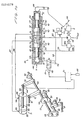
- a servomotor S2, or a second servomotor, for selectively making and breaking the hydraulic circuit is disposed centrally in the hollow clutch valve 80.
- the servomotor S2 has a piston shaft 86 slidably fitted in the central hole of the clutch valve 80, and a valve rod 87 threaded in one end of the piston shaft 86.
- the valve rod 87 has a partly spherical end on which a shoe 88 is pivotally mounted.
- the shoe 88 closes a confronting open end of the discharge port 54 of the distribution member 43 in a fluid-tight manner for thereby cutting off the flow of working oil from the discharge port 54 into the inner oil chamber 53a.
- the pump plungers 6 are hydraulically locked and the hydraulic pump P and the hydraulic motor M are directly connected to each other, so that the motor cylinder 8 can mechanically be driven by the pump cylinder 4 through the pump plungers 6 and the pump swash plate 22.
- the hydraulic pump P and the hydraulic motor M are directly interconnected in this manner when the motor swash plate 38 is vertically positioned for the minimum transmission ratio. In this transmission position, the efficiency of transmission of power from the input shaft to the output shaft is increased, and the thrust applied by the motor plungers l0 to the motor swash plate 38 is reduced, thus lessening the stresses on the bearings and other members.
- the piston shaft 86 has an outer end portion of smaller diameter defining an oil chamber 89 between itself and an inner member 82a of the thrust needle bearing 82 which supports the clutch valve 80.
- the oil chamber 89 is normally held in communication with the inner oil chamber 53a through an oil passage 90 defined axially in the piston shaft 86 and an oil passage 9l defined axially centrally in the valve rod 87 in communication with the oil passage 90.
- the piston shaft 86 has an integral piston 92 on its axially intermediate portion.
- An annular chamber 93 is defined axially leftwardly of the piston 92 and radially between the inner peripheral surface of the central hole of the clutch valve 80 and the outer peripheral surface of the piston shaft 86.
- the piston shaft 86 also has a central blind hole 94 extending from the outer end toward an axial position beyond the piston 92, the central blind hole 94 including a relief groove 95 defined in an inner peripheral surface of the piston shaft 86 at the inner end of the blind hole 94.
- the blind hole 94 and the annular chamber 93 communicate with each other through a radial hole 96a defined in the piston shaft 86 near the inner end of the piston 92.
- the outer end portion of the piston rod 86 has a hole 96b defined near the outer end of the piston 92 and providing communication between the oil chamber 89 and the blind hole 94.
- a rod-shaped second pilot valve 97 is inserted in the blind hole 94 and extends through the holder plate l7 secured to the end wall of the transmission case l.
- the seond pilot valve 97 has a land 98 on its inner distal end which is slidably held closely against the inner peripheral surface of the blind hole 94, and a smaller-diameter portion 99 positioned rightwardly of the land 98 and having a suitable axial dimension.
- the second pilot valve 97 also has a central axial hole l00 through which the blind hole 94 is vented to atmosphere.
- the second pilot valve 97 includes an outer end portion of smaller diameter which extends outwardly from an axially intermediate portion thereof.
- Outward sliding movement of the second pilot valve 97 is limited when the step at the inner end of the outer end portion of the second pilot valve 97 is engaged by a retaining ring l0l secured to the inner peripheral surface of the piston shaft 86 at its outer end.
- the second pilot valve 97 can be slidably moved horizontally in FIGS. l and 2 by the cam mechanism Cl which is operatively coupled to the outermost end of the second pilot valve 97 through a second link arm l02.
- the piston shaft 86 is now moved to the left because of the inequality: B - D > C since the pressure bearing area of the righthand end face of the piston 92 is expressed by B - D and the pressure bearing area of the inner end face of the piston shaft 86 is expressed by C.
- the piston shaft 86 is moved leftwardly until the shoe 88 engages the distribution member 43 to close the open end of the discharge port 54, whereupon the hydraulic pump P and the hydraulic motor M are directly interconnected.
- the high hydraulic pressure from the outlet port 54 (which is equal to the hyrdaulic pressure in the oil chamber 89) is exerted on the end face of the shoe 88 which has the pressure bearing area A, and the high hydraulic pressure in the oil chamber 89 acts on the righthand end face l03 of the piston 92 which has the pressure bearing area B - D.
- a > B - D the shoe 88 is subjected to a force tending to move the same to the right. The shoe 88 is therefore moved slightly to the right.
- the shoe 88 can be maintained in a hydraulically floating condition in which the shoe 88 and the outlet port 54 are well kept fluid-tight, reducing any oil leakage from between the shoe 88 and the outlet port 54 to a minimum.
- the second pilot valve 97 When the second pilot valve 97 is moved to the right, the smaller-diameter portion 99 of the second pilot valve 97 is displaced to the right beyond the righthand end face l03 of the piston 92, and the space around the samller-diameter portion 99 communicates with the hole 96b in the smaller-diameter end portion of the piston shaft 86.
- the high-pressure working oil therefore acts on the righthand end face l03 of the piston 92 and the inner end face of the piston shaft 86, and also acts on the lefthand end face of the piston 92 through the hole 96b, the space around the smaller-diameter portion 99, the hole 96a, and the annular chamber 93.
- the ratio-changing servomotor Sl is supplied with working oil from either the inner oil chamber 53a through a passage communicating with the inner oil chamber 53a via a first oil passage l04 defined in the fixed shaft 5l or the outer oil chamber 53b through a passage communicating with the outer oil chamber 53b via a second oil passage l05 defined in the holder plate l7 and a third oil passage l06 defined in the fixed shaft 5l. Switching between these passages is effected by a ball shuttle valve l07 positioned in a joint space defined in the holder plate l7 between the first and second oil passages l04, l05.
- the shuttle valve l07 is shifted to the right to close the open end of the second oil passage l05, communicating only the first oil passage l04 with the oil passsage 7l to supply the working oil from the inner oil chamber 53a to the ratio-changing servomotor Sl.
- the hydraulic pressure in the outer oil chamber 53b is higher than the hydraulic pressure in the inner oil chamber 53a.
- the shuttle valve l07 is shifted to the left to close the open end of the first oil passage l04, allowing only the second and third oil passages l05, l06 to communicate with the oil passage 7l.
- the working oil from the outer oil chamber 53b is supplied to the ratio-changing servomotor Sl.
- the ratio-changing servomotor Sl is supplied with sufficient hydraulic power at all times from the higher-pressure side in the closed hydraulic circuit.
- a replenishing pump F is mounted on an outer surface of the lefthand case member la.
- the replenishing pump F is driven by the input shaft 2 for feeding working oil from an oil tank (not shown) under a constant pressure.
- the replenishing pump F has an outlet port l08 communicating through an axial central oil passage l09 defined in the input shaft 2 with the outlet port 54 in the distribution member 43 via a check valve lll and also with the outer oil chamber 53b via a check valve ll0.
- the replenishing pump F therefore supplies oil to automatically complensate for any oil leakage from the closed hydraulic circuit composed of the hydraulic pump P and the hyraulic motor M.
- the cam mechanism Cl, the holder plate l7, and other members are covered with an end cover ll2 attached to the righthand side end of the transmission case l.
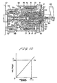
- a control system for controlling the transmission will be described mainly with reference to FIG. 3.
- the first link arm 72 coupled at one end to the first pilot valve 64 of the ratio-changing servomotor Sl for tilting the motor swash plate 38 has its opposite end fixed to a driver shaft l20.
- the driver shaft l20 is supported for rotation about its axis at opposite ends thereof by means of bearings l2l, l22 fixed to the holder plate l7.
- a driver cam l23 and a driver link arm l24 are also fixed to the driver shaft l20 on opposite sides of the first link arm 72.
- the second link arm l02 with one end coupled to the second pilot valve 97 of the servomotor S2 for making and breaking the hydraulic circuit has its opposite end fixed to a driven shaft l25 disposed below and extending parallel to the driver shaft l20.
- the driven shaft l25 has its opposite ends supported for rotation about its own axis the bearing l22 and a bearing l26 secured to the holder plate l7, the driven shaft l25 supporting a driven cam l27 engaging the driver cam l23.
- the driven cam l27 is loosely fitted over the driven shaft l25 so as to be rotatable thereon, but is axially immovable on the driven shaft l25.
- the driven shaft l25 has axial grooves l50 of a certain length defined therein adjacent to the driven cam l27.
- An arm l5l which is loosely fitted over the driven shaft l25 is rotatable with the driven shaft l25 through engagement in the axial grooves l50 and is axially movable on the driven shaft l25.
- the driven cam l27 and the arm l5l have complementarily shaped engaging members l27d, l5la, respectively, on confronting end faces thereof.
- the arm l5l is normally urged in a direction to bring the engaging members l27d, l5la into mutual engagement by a compression coil spring l52 disposed around the driven shaft l25.
- the second link arm l02 is normally urged to turn counterclockwise in a direction to pull the second pilot valve 97 out of the servomotor S2 by a torsion spring l53 disposed around the driven shaft l25.
- Angular movement of the second link arm l02 about the axis of the driven shaft l25 is limited to a certain angular range by a stopper l28 affixed to the holder plate l7 and engageable with the second link arm l02.
- the driver link arm l24 has its distal end coupled to a piston rod l29 of a ratio-changing hydraulic cylinder Jl.
- the hydraulic cylinder Jl comprsies a cylinder l30 having closed opposite ends, a piston l33 slidably fitted in the cylinder l30 and dividing the interior of the cylinder l30 into a head chamber l3l and a rod chamber l32, and the piston rod l29 integral with the piston l33 and axially movably extending in a fluid-tight manner through an end wall of the cylinder l30 adjacent to the rod chamber l32.
- the piston l33 and hence the piston rod l29 can be moved by oil under pressure supplied through a first electrohydraulic servovalve SVl for thereby turning the driver shaft l20 about its own axis.
- the swing link 84 projects radially from the outer end of the clutch valve 80 disposed between the servomotor S2 and the fixed shaft 5l (not shown in FIG. 3).
- the swing link 84 has a distal end coupled to the piston rod l54 of a clutch-controlling hydraulic cylinder J2 for turning the clutch valve 80, the hydraulic cylinder J2 being substantially identical in structure to the hydraulic cylinder Jl.
- the hydraulic cylinder J2 comprises a cylinder l60 and a piston l63 slidably movable therein and defining a head chamber l6l and a rod chamber l62.
- a sectorial shifter l55 is transversely mounted on the piston rod l54 of the hydraulic cylinder J2, the shifter l55 engaging the arm l5l on the driven shaft l25.
- the piston rod l54 is pushed away from the cylinder l60, the arm l5l is displaced by the shifter l55 to bring the engaging members l27d, l5la out of mutual engagement.
- the shifter l55 allows the engaging members l27d, l5la to remain in mutual engagement.
- the holes 83a, 83b of the clutch valve 80 and the ports 79a, 79b of the fixed shaft 5l are positioned such that when the piston rod l54 is pulled into the cylinder l60, the holes 83a, 83b and the ports 79a, 79b are displaced fully out of registry to cut off mutual fluid communication therebetween, and when the piston rod l54 is pushed away from the cylinder l60, the holes 83a, 83b and the ports 79a, 79b are shifted into registry to allow a fluid flow therebetween.
- the clutch-controlling hydraulic cylinder J2 is controlled through a second electrohydraulic servovalve SV2.
- the servovalves SVl, SV2 are directional control valves as well as continuously variable restrictors, and have a neutral position.
- the servovalves SVl, SV2 are responsive to current signals applied by a control unit CP to respective solenoids l34, l36 associated with the servovalves SVl, SV2 for controlling the rate of oil flow to be supplied to and discharged from the servovalves SVl, SV2.
- the first servovalve SVl for controlling the ratio-changing hydraulic cylinder l has four ports, i.e., a pump port Ppl, a tank port Ptl, and a pair of output ports Pal, Pbl, the output ports Pal, Pbl being connected via respective pipes l37, l38 to input ports l35, l36 of the head and rod chambers l3l, l32, respectively, of the hydraulic cylinder Jl.
- the pump port Ppl is coupled to a gear pump l39 (which may be the replenishing pump F) through a pipe l40.
- the tank port Ptl is connected to an oil tank l42 through a pipe l4l.
- a relief pipe l43 coupled to the oil tank l42 for returning oil to the oil tank l42 and having a relief valve l44. Oil under pressure fed from the gear pump l39 may be relieved to the oil tank l42 for keeping the hyraulic pressure in the pipes within a prescribed pressure range.
- the second servovalve SV2 for controlling the clutch-controlling hydraulic cylinder J2 has four ports, i.e., a pump port Pp2, a tank port Pt2, and a pair of output ports Pa2, Pb2, the output ports Pa2, Pb2 being connected via respective pipes l67, l68 to input ports l65, l66 of the head and rod chambers l6l, l62, respectively, of the hydraulic cylinder J2.
- the pump port Pp2 is coupled to the discharge pipe l40 of the gear pump l39 parallel to the pump port Ppl of the first servovalve SVl.
- the tank port Pt2 is connected to the oil tank l42 through the pipe l4l.
- the control unit CP for controlling the transmission control system comprises, for example, a D/A converter, an A/D converter, an interface, a CPU, a RAM, and a ROM which are interconnected by an address data bus.
- Various data items such as an engine rotational speed (r.p.m.), a throttle opening ( ⁇ th), a vehicle speed (Km/h), a shift position (SP), a braking deceleration (G), an oil temperature (O/t°C), and an engine cooling water temperature (W/t°C), are detected by respective sensors.
- the detected data items are processed according to map control, for example, to produce current signals that are then applied to the solenoids l34, l64 of the servovalves SVl, SV2 for operating the servovalves SVl, SV2 as indicated by Tables l, 2 (given later).
- the piston l33 (l63) of the hydraulic cylinder Jl (J2) is displaced to pull the piston rod l29 (l54) into the cylinder l30 (l60).
- the current applied to the solenoid l34 (l64) is suitable regulated to vary the restriction by the servovalve SVl (SV2) to vary the speed at which the piston l29 (l54) is displaced.
- the cam mechanism Cl comprises the driver cam l23 rotatable with the first link arm 72 coupled to the first pilot valve 64 of the ratio-changing servomotor Sl which actuates the motor swash plate 38, and the driven cam l27 rotatable with the second link arm l02 coupled to the second pilot valve 97 of the servomotor S2 which selectively makes and breaks the hydraulic circuit.
- the driver cam l23 comprises a semicircular portion l23a having a semicircular arc about the driver shaft l20, a lobe l23b projecting radially outwardly beyond the radius of the semicircular portion l23a, and a recess l23c defined radially inwardly within the radius of the semicircular portion l23a.
- the driver cam l23 has a profile composed of the semicircular portion l23a, the lobe l23b, and the recess l23c which are smoothly joined.
- the driven cam l27 comprises an arcuate portion l27a having a concave surface of substantially the same curvature as that of the semicircular portion l23a and a straight portion l27b extending substantially tangentially to the arcuate portion l27a.
- the second link arm l02 is now turned clockwise with the driven shaft l25 to move the second pilot valve 97 to the left.
- the shoe 33 is moved leftwardly with the piston shaft 86 of the servomotor S2 under hydraulic pressure, as described above, to close the outlet port 54.
- the first pilot valve 64 of the ratio-changing servomotor Sl is at the rightward position, and hence the motor swash plate 38 is in the vertical position for the minimum transmission ratio.
- the outlet port 54 remains closed since the opposite ends of the driven cam l27 is engaged by the lobe l23b and the recess l23c of the driver cam l23 against angular movement in any direction.
- the recess l23c engages an end l27c of the driven cam l27 remote from the straight portion l27b to turn the second link arm l02 in a direction to move the second pilot valve 97 to the right.
- the driver and driven cams l23, l27 are profiled such that while the parts are moving from the position of FIG. 6 to the position of FIG. 5, the lobe l23b and the straight portion l27b are kept out of contact with each other. Therefore, upon an increase in the transmission ratio, the outlet port 54 can immediately be opened.
- the outlet port 54 of the hydraulic pump P can be opened and closed through the second pilot valve 97 by the cam mechanism Cl which can reliably operate with a relatively small force applied.
- the second pilot valve 97 and hence the servovalve S2 has a high degree of operation reliability.
- the torsion spring l53 keeps the lobe l23b and the straight portion l27b in contact with each other, thus eliminating play or backlash and reducing hysteresis.
- the spring force of the spring l53 may be quite small, so that its effect on the hydraulic cylinder Jl is negligible.
- the motor swash plate 38 and the clutch valve 80 may be electrically controlled by step motors or motor- driven linear actutators, rather than the hydraulic cylinders Jl, J2.
- the control system may employ a mechanical control arrangement using a governor and the like, or a purely hydraulic control arrangement, instead of the electronic control unit CP.
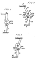
- FIGS. 7 through 9 show a cam mechanism C2 according to another embodiment of the present invention.
- the cam mechanism C2 shown in FIGS. 7 through 9 comprises a driver plate l70 fixed to the driver shaft l20 and having a cam groove l7l and a driven arm l72 fixed to the driven shaft l25 and having a pin l73 movably riding in the cam groove l7l for transmitting motion between the driver and driven shafts l20, l25.
- the cam groove l7l includes an arcuate portion l7la extending through a certain angle around the driver shaft l20 and a straight portion l7lb extending obliquely radially outwardly from the upper end of the arcuate portion l7la.
- the pin l73 is located at the lower end of the cam groove l7l.
- the cam plate l70 is turned, but the pin l53 is not moved since it is positioned in the arcuate portion l7la of the cam groove l7l. Therefore, as long as the pin l73 rides in the arcuate portion l7la, the second pilot valve 97 remains still.
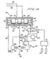
- FIG. l0 shows a control system according to still another embodiment of the present invention.
- the hydraulic cylinder Jl is controlled by a hydraulic control valve DV which doubles as a directional control valve and a continuous restrictor and has a neutral position.
- the control valve DV controls the rate of oil flow supplied to and discharged from the hydraulic cylinder Jl according to the amount of opening of a throttle valve and the rotational speed of an engine.
- the control valve DV has a pump port Pp, three tank ports Pt, and a pair of output ports Pa, Pb.
- the output ports Pa, Pb are connected through the pipes l37, l38, respectively, to the input ports l35, l36 of the head and rod chambers l3l, l32 of the hydraulic cylinder Jl.
- the pump port Pp is coupled to the gear pump l39 through the pipes l40, and the tank ports Pt are coupled to the oil tank l42 through the pipe l4l.
- the relief pipe l43 is connected between the gear pump l39 and the pump port Pp for relieving oil under pressure from the gear pump l39 through the relief valve l44 into the oil tank l42 for thereby keeping the oil pressure in the pipes within a prescribed pressure range.
- the gear pump l39 is operatively coupled to the engine, denoted at E, for delivering working oil under pressure from the oil tank l42.
- the gear pump l39 has a rotatable shaft connected at one end to a hydraulic governor l45.
- the hydraulic governor l45 has an input port l45a coupled to the discharge pipe l40 of the gear pump l39 and an output port l45b coupled by a pipe l46 to a governor pressure input port Pg of the control valve DV. Therefore, the hydraulic governor l45 can apply a governor hydraulic pressure proportional to the rotational speed of the engine E to the control valve DV.
- the control valve DV has a spool l47 reciprocally slidably disposed in the valve casing for controlling the direction of oil flows across the control valve DV.
- the spool l47 has one end l47a subjected to the pressure of the oil discharged from the gear pump l39 and introduced through a pump pressure input port Pi.
- the discharge pipe l40 of the gear pump l39 and the pump pressure inlet port Pi are interconnected by a pipe l48 having a solenoid-operated directional control valve EV which comprises a two-position, three-way valve.
- the directional control valve EV is normally in a position in which the pump pressure input port Pi and the oil tank l42 communicate with each other.
- the directional control valve EV has a solenoid l49 which is energized by a signal from a control unit Cc (described later on) for shifting the valve into a position in which the discharge pipe l40 of the gear pump l39 communicates with the pump pressure input port Pi.
- the spool l47 has three axially spaced lands l8l held in close, slidable contact with an inner cylindrical surface l80 defined in the valve casing of the control valve DV, and smaller-diameter portions l82 disposed axially between the lands l8l for allowing working oil to flow around the smaller-diameter portions l82.
- the spool l47 can change the rates and directions of flows of working oil across the control valve DV by varying the relative position between the lands l8l, the smaller-diameter portions l82, and the ports Pa, Pb, Pp, Pt.
- the end l47a of the spool l47 is of a diameter smaller than that of the lands l8l, and extends axially and is closely slidably fitted in a guide hole l85 defined in the control valve casing.
- the guide hole l85 and the spool end l47a define a pump oil chamber l86 communicating with the pump pressure input port Pi.
- the land l8l closest to the spool end l47a has an end face l8la on which the coil spring l83 acts, the end face l8la and the inner cylindrical surface l80 jointly defining a governor oil chamber l87 communicating with the governor input port Pg.
- the hydraulic pressures applied through the input ports Pi, Pg and the resilient force from the coil spring l83 jointly impose a force Fr tending to move the spool l47 to the right.
- the coil spring l84 acting on the other end of the spool l47 can be compressed by a cam lever l88 operatively coupled to an accelerator pedal l89 associated with the engine E. As the throttle valve is opened by depressing the accelerator pedal l89, the cam lever l88 pushes the coil spring l84 to increase a force Fl tending to move the spool l47 to the left.
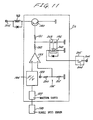
- the control unit Cc for controlling the solenoid-operated directional control valve EV comprises an NPN transistor l90 connected in series to the solenoid l49, a comparator l93 connected to the base of the transistor l90 via series-connected resistors l9l, l92, a frequency-to-voltage converter l94 connected to a noninverting input terminal (+) of the comparator l93, a reference level setting circuit l95 coupled to an inverting input terminal (-) of the comparator l93, and a relay unit l96 for selectively draining an output signal from the comparator l93 to ground.
- the frequency-to-voltage converter l94 is coupled to a vehicle speed sensor l98 through a waveform shaper l97.
- An electric signal representative of a vehile speed, issued from the vehicle speed sensor l98, is processed by the waveform shaper l97, and then converted by the frequency-to-voltage converter l94 to a voltage signal Ev proportional to the vehicle speed, as shown in FIG. l2.
- the reference level setting circuit l95 includes a first voltage-divider resistor 200 coupled to a reference voltage terminal l99 and a second voltage-divider resistor 20l connected in series to the first voltage-divider resistor 200 and to ground.
- the relay unit l96 is responsive to energization of a coil 202 thereof for opening a movable contact 203.
- the coil 202 is connected to a positive power supply terminal 206 through an angle sensor 205 having a movable contact 204 which is operatively coupled to the hydraulic cylinder Jl.
- the movable contact 204 is closed when the angle of inclination of the motor swash plate 38 is substantially minimal.
- the reference voltage of the comparator l93 is a voltage Eo which is produced by dividing the voltage applied to the reference power supply terminal l99 by the voltage-divider resistors 200, 20l.
- the reference voltage Eo corresponds to a relatively high vehicle speed Vh (see FIG. l2). Therefore, when the voltage Ev commensurate with the vehicle speed, applied to the noninverting input terminal (+) of the comparator l93, is equal to or higher than the reference voltage Eo, i.e., when the vehicle speed reaches or exceeds a prescribed vehicle speed, the transistor l90 is rendered conductive to energize the solenoid l49.
- the solenoid l49 of the solenoid-operated directional control valve EV is energized only when the angle of the motor swash plate 38 is substantially minimal and the vehicle speed reaches or exceeds the prescribed vehicle speed.
- the cam mechanism Cl shown in FIG. l0 is essentially the same as that shown in FIG. 3 except that the driven cam l27 is fixed to the driven shaft l25.
- the control system shown in FIG. l0 for controlling the hydraulically operated continuously variable transmission will operate as follows:
- the transmission ratio decreases, the engine load is increased to suppress an increase in the engine rotational speed, with the result that Fr ⁇ Fl. While the operation indicated in the Table 3 is being repeated within a short period of time, the transmission ratio is controlled such that the engine rotational speed will be kept substantially at a constant level according to the amount of opening of the throttle valve.
- the servomotor S2 is operated by the cam mechanism Cl to close the outlet port 54 of the hydraulic pump P.
- the solenoid l49 of the directional control valve EV is energized by the control unit Cc to introduce the oil discharged under pressure from the gear pump l39 into the pump oil chamber l86 in the control valve DV.
- the force Fr is held higher than the force Fl irrespective of how the engine rotational speed may change, and the motor swash plate 38 is also locked in its position for the minimum transmission ratio. Therefore, the servomotor S2 is free from hunting.
- the solenoid l49 of the directional control valve EV is de-energized, and hence no pump oil pressure is added to the force Fr tending to move the spool l47 to the right. Accordingly, the motor swash plate 38 is not locked.
- the servomotor S2 is also free from hunting at this time inasmuch as the rate of reduction in the engine rotational speed due to the closing of the hydraulic circuit is low.
- the solenoid-operated directional control valve EV may suffer from hunting due to contact chatter. However, such hunting can be avoided by adding a hysteresis circuit to the control unit Cc.
- the motor swash plate 38 is controlled as a function of the amount of opening of the throttle valve and the engine rotational speed.
- the motor swash plate 38 is locked in its least inclined position regardless of how the engine rotational speed may vary.
- the servomotor S2 is prevented from hunting in response to the motor swash plate 38.
- FIG. l3 illustrates a hydraulic control arrangement according to a further embodiment of the present invention.
- the governor oil pressure and the pump oil pressure are selectively applied through a solenoid-operated directional control valve EV ⁇ to an input port Pgi from which the oil pressure is imposed on the lefthand end of the spool l47.
- the directional control valve EV ⁇ is actuated by a signal from the control unit Cc to apply only the pump oil pressure to the spool l47.
- the forces Fr, Fl are selected such that when the governor oil pressure is applied, Fr ⁇ Fl, and when the pump oil pressure is applied, Fr > Fl.
- FIG. l4 illustrates a hydraulic control arrangement according to a still further embodiment of the present invention.
- the force Fl tending to move the spool l47 to the left is obtained by throttle oil pressure commensurate with the throttle valve opening and applied to the righthand end the spool l47 through a throttle oil pressure input port Ps.
- the throttle oil pressure is applied from a pressure regulator valve 207 operatively connected to the accelerator pedal l89 and supplied with the pump oil pressure.
- the pressure regulator valve 207 is connected to the input port Ps through a pipe 208 which is selectively openable and closable by the solenoid-operated directional control valve EV.
- the governor oil pressure is applied to the lefthand end of the spool l47 to apply the force Fr tending to move the spool l47 to the right.
- the spool l47 of the control valve DV is controlled under the coil spring forces and hydraulic pressures applied thereto for controlling the motor swash plate 38.
- spool l47 may be controlled by map control using a CPU, for example.
- cam mechanisms Cl, C2 for operatively connecting the servomotors Sl, S2 are not limited to the illustrated arrangements, but may be modified in various ways.
- the motor swash plate may be operated by an actuator, and the hydraulic circuit may be selectively made and broken by another actuator.
- the detection of the throttle valve opening or the accelerator pedal depression as an indication of the driver's intention of acceleration and deceleration may be replaced with the detection of the vacuum developed in the intake pipe of the engine, and the amount of fuel supplied.
- the transmission ratio is controlled on the basis of the engine rotational speed.
- the transmission ratio may be controlled on the basis of the engine torque.
- the present invention provides a hydraulically operated continuously variable transmission which can reliably cut off power transmission between input and output shafts when the clutch is OFF and which is capable of delicate clutch control; and furthermore provides a hydraulically operated continuously variable transmission including means for reliably making and breaking a hydraulic circuit even with a relatively small force and which is relatively small in size and simple in structure; and furthermore provides hydraulically operated continuously variable transmission having means capable of preventing a motor swash plate from hunting.
Landscapes
- Engineering & Computer Science (AREA)
- General Engineering & Computer Science (AREA)
- Mechanical Engineering (AREA)
- Control Of Fluid Gearings (AREA)
- Reciprocating Pumps (AREA)
Abstract
Description
- The present invention relates to a hydraulically operated continuously variable transmission, and more particularly to a hydraulically operated continuously variable transmission including a hydraulic pump coupled to an input shaft and a hydraulic motor coupled to an output shaft, the hydraulic pump and the hydraulic motor being interconnected by a hydraulic circuit.
- There is known a hydraulically operated continuously variable transmission for use in an automobile, including an input shaft, a hydraulic pump having a pump cylinder coupled to the input shaft and a plurality of pump plungers disposed in the pump cylinder in an annular pattern around an axis of rotation of the pump cylinder, the hydraulic pump having an outlet port, an output shaft, a hydraulic motor having a motor cylinder coupled to the output shaft and a plurality of motor plungers disposed in said motor cylinder in an annular pattern around an axis of rotation of the motor cylinder, the hydraulic motor having an inlet port, a closed hydraulic circuit interconnecting the hydraulic pump and the hydraulic motor, a pump swash plate for reciprocally moving the pump plungers, a tiltable motor swash plate for rotating the motor cylinder in response to reciprocating movement of the pump plungers, the tiltable motor swash plate being tiltable through a continuously variable angle for continuously adjusting the stroke of reciprocating movement of the motor plungers.
- As disclosed in Japanese Patent Publications Nos. 32-7l59 and 56-50l42, for example, such a continuously variable transmission is controlled such that the transmission ratio will be l : l while minimizing or eliminating the angle of inclination of the motor swash plate.
- By breaking the hydraulic circuit which interconnects the outlet port of the hydraulic pump and the inlet port of the hydraulic motor, the pump plungers can be locked in the pump cylinder to drive the motor cylinder mechanically through the pump swash plate. With the hydraulic motor and pump thus mechanically locked, the oil pressure discharged by the hydraulic pump is prevented from acting on the motor plungers to reduce the thrust load on the motor swash plate and also to reduce oil leakage from between the motor plungers and the motor cylinder.
- Where a shoe is mounted on the distal ends of the motor plungers and a hydraulic pressure introduced to the sliding surface of the shoe for balancing the hydraulic pressures, the hyraulic pressure on the sliding surface of the shoe can be lowered and any oil leakage can be reduced by breaking the hydraulic circuit.
- It is known that it is possible to improve the power transmission efficiency of the transmission and increase the durability of the transmission by breaking the hydraulic circuit between the hydraulic pump and the hydraulic motor.
- It is general for a hydraulically operated continuously variable transmission to have a passage capable of communication between the outlet and inlet ports of the hydraulic pump and also to have a clutch valve for varying the cross-sectional area of the passage to change the amount of power transmitted between the hydraulic pump and the hydraulic motor thereby to control power transmission between the input and output shafts.
- Japanese Laid-Open Patent Publication No. 54-l34252 discloses a common valve for closing and opening the outlet port of the hydraulic pump and for regulating the amount of oil flow through the passage between the outlet and inlet ports of the hydraulic pump. In such a disclosed arrangement, since the outlet port of the hydraulic pump is selectively closed and opened and the clutch valve is continuously operated or under analog control, delicate clutch control could not be achieved if the outlet port of the hydraulic pump and the clutch valve were controlled by a single actuator.
- The making and breaking of the hydraulic circuit and the clutch valve are separately controlled by independent actuators in a transmission disclosed in Japanese Laid-Open Patent Publication No. 55-l52622. However, if the outlet port of the hydraulic pump were opened at the time the clutch valve is controlled to make the clutch OFF in order to bring the transmission into a neutral condition, the hydraulic pump and the hydraulic motor would be mechanically coupled by the pump plungers and the pump swash plate, and the power would not be cut off even if the clutch is OFF.
- Japanese Patent Publication No. 56-50l42 discloses an arrangement for making and breaking the hydraulic circuit by providing a piston rod which can break the hydraulic circuit and applying a hydraulic pressure to the piston rod to break the hydraulic circuit.
- The hydraulic circuit is made under the resiliency of a return spring, which should be capable of producing a relatively large spring force in order to make the hydraulic circuit reliably. An actuator employed for moving the piston rod to breaking the hydraulic circuit against the force of the return spring should therefore be capable of applying a large force and needs to be large in size. The disclosed arrangement is not preferable for this reason.
- One solution is to use a hydraulic servomotor for operating a device to make and break the hydraulic circuit with a relatively small force, as disclosed in Japanese Laid-Open Patent Publication No. 54-l34253. A valve for making and breaking the hydraulic circuit is operated by a pilot valve which is also governed by a spring force. In order to ensure reliable operation, therefore, a large spring force must be established, and the resulting system is large in size.
- As disclosed in Japanese Laid-Open Patent Publications Nos. 54-l34252 and 55-l43l2, for example, it is known that in order to achieve smooth and economical operation of a motor vehicle, it is effective to control the transmission so that the amount of opening of the throttle valve and the engine rotational speed will be proportional to each other.
- When the hydraulic circuit is broken at the time the transmission ratio is minimal, since the volumetric efficiency becomes higher than before the circuit is broken, the engine rotational speed is lowered as indicated by the following equations:

- Therefore, in a motor vehicle in which the transmission is controlled as a function of the throttle valve opening and the engine speed, the following steps are repeated if the throttle valve opening is kept at a substantially constant level:
- (l) The transmission ratio becomes l (the angle of the motor swash plate is minimal);
- (2) The device for making and breaking the hydraulic circuit is operated to break the circuit;
- (3) The engine rotational speed is lowered due to an increase in the volumetric efficiency;
- (4) The angle of the motor swash plate is controlled so as to increase the transmission ratio;
- (5) The hydraulic circuit is established again; and
- (6) The transmission ratio becomes l again.
- When the above steps are repeated in a short period of time, the device for making and breaking the hydraulic circuit is subjected to hunting, and smooth running of the vehicle may not be achieved.
- The same problem is likely to happen when the transmission is controlled on the basis of the engine torque in order to obtain minimum fuel consumption. More specifically, when the engine rotational speed is reduced, the engine torque is increased, and the angle of the motor swash angle is controlled in the same manner as described above. The device for making and breaking the hydraulic circuit now suffers from hunting.
- According to the present invention, there is provided a hydraulically operated continuously variable transmission comprising an input shaft, a hydraulic pump coupled to the input shaft and having inlet and outlet ports, an output shaft, a variable-displacement hydraulic motor coupled to the output shaft, a closed hydraulic circuit interconnecting the hydraulic pump and the hydraulic motor and including a passage connecting the inlet and outlet ports of the hydraulic pump, a servomotor for making and breaking the hydraulic circuit respectively by opening and closing the outlet port, a clutch valve for continuously varying the cross-sectional area of the passage to change the amount of power transmitted between the hydraulic pump and the hydraulic motor, and a control system for independently controlling the servomotor and the clutch valve, the control system being arranged to hold the servomotor in a position to open the outlet port when the clutch valve is opened beyond a prescribed degree.
- According to the present invention, there is also provided a hydraulically operated continuously variable transmission comprising an input shaft, a hydraulic pump having a pump cylinder coupled to the input shaft and a plurality of pump plungers disposed in the pump cylinder in an annular pattern around an axis of rotation of the pump cylinder, the hydraulic pump having an outlet port, an output shaft, a hydraulic motor having a motor cylinder coupled to the output shaft and a plurality of motor plungers disposed in said motor cylinder in an annular pattern around an axis of rotation of the motor cylinder, the hydraulic motor having an inlet port, a closed hydraulic circuit interconnecting the hydraulic pump and the hydraulic motor, a pump swash plate for reciprocally moving the pump plungers, a tiltable motor swash plate for rotating the motor cylinder in response to reciprocating movement of the pump plungers, the tiltable motor swash plate being tiltable through a continuously variable angle for continuously adjusting the stroke of reciprocating movement of the motor plungers, a first hydraulic servomotor operable by a first pilot valve for varying the angle of inclination of the motor swash plate, a second hydraulic servomotor operable by a second pilot valve for selectively connecting and disconnecting the outlet and inlet ports, and a cam mechanism operatively coupling the first and second pilot valves.
- According to the present invention, there is further provided a hydraulically operated continuously variable transmission comprising an input shaft, a hydraulic pump having a pump cylinder coupled to the input shaft and a plurality of pump plungers disposed in the pump cylinder in an annular pattern around an axis of rotation of the pump cylinder, the hydraulic pump having an outlet port, an output shaft, a hydraulic motor having a motor cylinder coupled to the output shaft and a plurality of motor plungers disposed in said motor cylinder in an annular pattern around an axis of rotation of the motor cylinder, the hydraulic motor having an inlet port, a closed hydraulic circuit interconnecting the hydraulic pump and the hydraulic motor, a pump swash plate for reciprocally moving the pump plungers, a tiltable motor swash plate for rotating the motor cylinder in response to reciprocating movement of the pump plungers, the tiltable motor swash plate being tiltable through a continuously variable angle for continuously adjusting the stroke of reciprocating movement of the motor plungers, detector means for detecting an operating condition of an engine which drives the input shaft, means for disconnecting the outlet and input ports when the angle of the motor swash plate is substantially minimal, and control means responsive to a signal from the detector means for tilting the motor swash plate to operate the engine in a prescribed condition, the control means being arranged such that when a vehicle incorporating the hydraulically operated continuously variable transmission runs at a prescribed speed or a higher speed and the angle of the motor swash plate is substantially minimal.
- Some embodiments of the invention will now be described by way of example and with reference to the accompanying drawings, in which:-
- FIG. l is a longitudinal cross sectional view of a hydraulically operated continuously variable transmission according to the present invention;
- FIG. 2 is an enlarged cross-sectional view of a servomotor for selectively connecting and disconnecting a hydraulic circuit in the hydraulically operated continuously variable transmission shown in FIG. l;
- FIG. 3 is a schematic view showing a control system for controlling the hydraulically operated continuously variable transmission;
- FIGS. 4 through 6 are views showing operation of a cam mechanism in the hydraulically operated continuously variable transmission;
- FIGS. 7 through 9 are views showing operation of a cam mechanism according to another embodiment of the present invention;
- FIG. l0 is a schematic view of a control system according to still another embodiment of the present invention;
- FIG. ll is a circuit diagram, partly in block form, of a control unit employed in the control system shown in FIG. l0;
- FIG. l2 is a graph showing the relationship between a vehicle speed and a voltage;
- FIG. l3 is a hydraulic circuit diagram of a hydraulic control arrangement according to a further embodiment of the present invention; and
- FIG. l4 is a hydraulic circuit diagram of a hydraulic control arrangement according to a still further embodiment of the present invention.
- Like or corresponding parts are denoted by like or corresponding reference numerals throughout several views.
- FIG. l shows a hydraulically operated continuously variable transmission according to the present invention, the transmission basically comprising a hydraulic pump P and a hydraulic motor M housed in a transmission case l composed of a pair of longitudinally separated case members la, lb.
- The hydraulic pump P has a
pump cylinder 4 splined to anend 3 of aninput shaft 2, a plurality of cylinder holes or bore 5 defined in thepump cylinder 4 in a circular pattern around and concentric with theinput shaft 2 and extending parallel to theinput shaft 2, and a plurality of pump plungers 6 slidably fitted respectively in the cylinder holes 5. The hydraulic pump P can be driven by the power of an engine (not shown) which is transmitted through aflywheel 7 coupled to the opposite end of theinput shaft 2. - The hydraulic motor M has a
motor cylinder 8 disposed in surrounding relation to thepump cylinder 4, a plurality of cylinder holes orbore 9 defined in themotor cylinder 8 in a circular pattern around and concentric with theinput shaft 2 and extending parallel to theinput shaft 2, and a plurality of motor plungers l0 slidably fitted respectively in thecylinder holes 9. The hydraulic motor M is rotatable relatively to thepump cylinder 4 in concentric relation thereto. - The
motor cylinder 8 has axially opposite ends on which a pair of support shafts lla, llb is disposed, respectively. The support shaft lla is rotatably supported on the axial end wall of the case member lb by means of a ball bearing l2, and the support shaft llb is rotatably supported on the axial end wall of the case member la by means of a needle bearing l3. - The ball bearing l2 has an inner race l2a and an outer race l2b. The support shaft lla has an outer end projecting beyond the inner race l2a and on which a stop ring l4 is mounted. Another stop ring l5 is mounted on an outer peripheral surface of the outer race l2b near an outer end thereof, and is received in an annular recess l6 defined in an outer surface of the axial end wall of the case member lb. A holder plate l7 held against an outer end surface of the outer race l2b is fixed by bolts l8 to the axial end wall of the case member lb. The ball bearing l2 and the support shaft lla are thus fixedly mounted on the case member lb against axial movement.
- The other support shaft llb has an integral gear l9 meshing with an
idler gear 20 for transmitting output power of the hydraulic motor M therethrough to a differential gear mechanism 2l. - A pump swash plate 22 inclined at an angle to the pump plungers 6 is fixedly disposed radially inwardly of the
motor cylinder 8. An annular pump shoe 23 is rotatably slidably supported on an inclined surface of the pump swash plate 22. - Each of the pump plungers 6 has a bottomed hole 24 opening toward the pump swash plate 22. A connecting rod 25 is inserted in each pump plunger 6 and pivotally movable with respect to the pump plunger 6 by means of a ball joint 26a on the inner end of the connecting rod 25. The connecting rod 25 projects out of the corresponding pump plunger 6 from the bottomed hole 24, and is pivotally movable with respect to the pump shoe 23 by means of a ball joint 26b on the outer projecting end of the connecting rod 25.
- The annular pump shoe 23 has its outer peripheral surface supported in the
motor cylinder 8 by aneedle bearing 27. The annular pump shoe 23 has anannular step 23a defined in its inner peripheral surface facing the pump plungers 6. A presser ring 28 riding in theannular step 23a presses the pump shoe 23 toward the pump swash plate 22 under the resiliency of acompression coil spring 30 disposed under compression around theinput shaft 2 and acting on aspring holder 29 held against the presser ring 28. Thespring holder 29 is slidably fitted over splines 3l on theinput shaft 2, and has a partly spherical surface contacting a complementary partly spherical surface of the presser ring 28. Therefore, thespring holder 29 is neatly held against the presser ring 28 for transmitting the resilient force from thespring 30 to the presser ring 28 irrespective of how thespring holder 29 and the presser ring 28 are relatively positioned. - Thus, the pump shoe 23 can be slidingly rotated in a fixed position on the pump swash plate 22 at all times.
- Bevel gears 32, 33, which have the same number of teeth, are fixed respectively to the confronting surfaces of the pump shoe 23 and the
pump cylinder 4 and are held in mesh with each other. When thepump cylinder 4 is driven to rotate by theinput shaft 2, the pump shoe 23 is rotated in synchronism with thepump cylinder 4 through the meshingbevel gears - During the above operation, paths followed by the centers of the
ball joints 26a, 26b on the opposite ends of the connecting rods 25 do not lie in the same cylindrical plane because of the inclination of the pump swash plate 22, i.e, the pump shoe 23. Since, however, the connecting rods 25 are pivotally moved about the ball joints 26a in the bottomed holes 24 of the pump plungers 6 according to the different paths of rotation of theball joints 26a, 26b, the pump plungers 6 can smoothly be slid in the respective cylinder holes 5. Substantially one half of the pump plungers 6 are always in the discharge stroke, and hence corresponding one half of the pump shoe 23 is pressed against the pump swash plate 22 by the connecting rods 25 under a high hydraulic pressure developed in oil chambers defined in thepump cylinder 4 behind the pump plungers 6. At the same time, the other half of the pump shoe 23 is also subjected to the same high hydraulic pressure. Accordingly, the entire sliding surface of the pump shoe 23 is pressed against the pump swash plate 22 at all times, and remains closely in contact with the pump swash plate 22 without the danger of being lifted off even when an abrupt pressure drop is developed for some reason in oil chambers behind those pump plungers 6 which operate in the suction stroke. - The pump shoe 23 has hydraulic pockets 34 defined in its surface held against the pump swash plate 22 and positioned in alignment with the respective connecting rods 25. The hydraulic pockets 34 communicate with the respective oil chambers in the
pump cylinder 4 throughoil holes 35 defined in the pump plungers 6, oil holes 36 defined in the connecting rods 25, andoil holes 37 defined in the pump shoe 23. While thepump cylinder 4 is in operation, therefore, oil under pressure in thepump cylinder 4 is supplied to the hydraulic pockets 34 to apply a hydraulic pressure to the pump shoe 23 in a direction to bear the thrust force imposed by the pump plungers 6 on the pump shoe 23. Therefore, the oil supplied to the hydraulic pockets 34 serves to reduce the pressure under which the pump shoe 23 contacts the pump swash plate 22, and also to lubricate the mutually sliding surfaces of the pump shoe 23 and the pump swash plate 22. - A
motor swash plate 38 is tiltably supported in the transmission case l by means of a pair oftrunnions 39 projecting from opposite sides of themotor swash plate 38, which is held in confronting relation to the motor plungers l0. Themotor swash plate 38 has an inclined surface on which there is slidably disposed amotor shoe 40 that is pivotally coupled to ball joints l0a on the outer ends of the motor plungers l0. - Each of the motor plungers l0 reciprocally moves in expansion and compression strokes while rotating the
motor cylinder 8. The stroke of the motor plungers l0 can be adjusted from zero to a maximum level by varying the angle of inclination of themotor swash plate 38 from a vertical position (shown by the two-dot-dash lines) in which themotor swash plate 38 lies perpendicularly to the motor plungers l0 to a most inclined position (shown by the solid lines), as described later on. - The
motor cylinder 8 comprises axially separate first through fourth members or segments 8a through 8d. The first member 8a includes the support shaft llb and accommodates the pump swash plate 22. Thesecond member 8b has guide holes 4l in the cylinder holes 9, in which the motor plungers l0 are slidably guided, respectively. The third andfourth members 8c, 8d haveoil chambers 42 in the cylinder holes 9, theoil chambers 42 being slightly larger in diameter than the guide holes 4l. The third member 8c serves as adistribution member 43 having oil passages leading to the cylinder holes 5, 9, and thefourth member 8d includes the suppoer shaft lla. - The first member 8a has an integral joint flange 44 on its end facing the
second member 8b. The joint flange 44 is fitted relatively tightly in a positioning hole 45 defined in the end face of thesecond member 8b that confronts the joint flange 44. The joint flange 44 is fastened to thesecond member 8b by means of a plurality of bolts 46. The second, third, andfourth members bolts 48. - The
input shaft 2 has an outer end portion rotatably supported centrally in the support shaft llb of themotor cylinder 8 by aneedle bearing 49, and an inner end portion rotatably supported centrally in thedistribution member 43 by a needle bearing 50. - The
spring 30 is disposed under compression between thepump cylinder 4 and thespring holder 29 for pressing thepump cylinder 4 against thedistribution member 43 to prevent oil from leaking from the sliding surfaces of thepump cylinder 4 and thedistribution member 43. The resilient force of thespring 30 is also effective in supporting thespring holder 29, the presser ring 28, the pump shoe 23, and the pump swash plate 22 firmly in themotor cylinder 8, as described above. - The support shaft lla is of a hollow structure in which a fixed shaft 5l is centrally inserted. A
distribution ring 52 is fitted over the inner end of the fixed shaft 5l in a fluid-tight manner through an O-ring therebetween. Thedistribution ring 52 has an axial end face held eccentrically in sliding contact with thedistribution member 43. Thefourth member 8d of themotor cylinder 8 has an interiorhollow space 53 which is divided by thedistribution ring 52 into aninner oil chamber 53a and anouter oil chamber 53b. - The
distribution member 43 has an outlet port 54 and aninlet port 55. The outlet port 54 provides fluid communication between the cylinder holes 5 that receive the pump plungers 6 operating in the discharge stroke and theinner oil chamber 53a. Theinlet port 55 provides fluid communication between the cylinder holes 5 that receive the pump plungers 6 operating in the suction stroke and theouter oil chamber 53b. Thedistribution member 43 also has a number ofcommunication ports 56 defined therein and through which the cylinder holes 9 of themotor cylinder 8 communicate with theinterior space 53 in thefourth member 8d. - Therefore, a closed hydraulic circuit is formed between the hyraulic pump P and the hydraulic motor M through the
distribution member 43 and thedistribution ring 52. When thepump cylinder 4 is driven by theinput shaft 2, high-pressure working oil discharged by the pump plungers 6 in the discharge stroke flows from the outlet port 54, theinner oil chamber 53a, and thecommunication ports 56 communicating with theinner oil chamber 53a into the cylinder holes 9 receiving the motor plungers l0 which are in the expansion stroke, thereby imposing a thrust on these motor plungers l0. Working oil discharged by the motor plungers l0 operating in the compression stroke flows through thecommunication ports 56 communicating with theouter oil chamber 53b and theinlet port 55 into the cylinder holes 5 receiving the pump plungers 6 in the suction stroke. Upon such circulation of the working oil, themotor cylinder 8 is driven by the sum of the reactive torque applied by the pump plungers 6 in the discharge stroke to themotor cylinder 8 through the pump swash plate 22 and the reactive torque received by the motor plungers l0 in the expansion stroke from themotor swash plate 38. - The transmission ratio of the
motor cylinder 8 to thepump cylinder 4 is given by the following equation:
- It can be understood from the above equation that the transmission ratio can be varied from l to a desired value by varying the displacement of the hydraulic motor M from zero to a certain value.
- Since the displacement of the hydraulic motor M is determined by the stroke of the motor plungers l0, the transmission ratio can continuously be adjusted from l to a certain value by tilting the
motor swash plate 38 from the vertical position to a ceratin inclined position. - A hydraulic ratio-changing servomotor Sl, or a first servomotor, for tilting the
motor swash plate 38 is disposed in an upper portion of the transmission case l. The ratio-changing servomotor Sl comprises aservo cylinder 58 fixed to the transmission case l, a servo piston 6l movably disposed in theservo cylinder 58 and dividing the interior space of theservo cylinder 58 into alefthand oil chamber 59 and arighthand oil chamber 60, apiston rod 62 integral with the servo piston 6l, and a rod-shapedfirst pilot valve 64 slidably fitted in avalve hole 63 defined in thepiston rod 62 and extending from an end face of the servo piston 6l. - The piston rod 6 integral with the servo piston 6l extends through the
servo cylinder 58 and has an end projecting into the transmission case l. The projecting end of thepiston rod 62 is coupled to themotor swash plate 38 through aconnector 65 and pivot pins. - The
first pilot valve 64 has on its distal end aland 64a intimately fitted in thevalve hole 63 and also has a pair of diametricallyopposite recesses 64b defined behind theland 64a and extending over a certain axial dimension. A retainingring 66 is securely fitted over thefirst pilot valve 64 behind therecess 64b. The retainingring 66 is engageable with a retainingring 67 fixed to the inner peripheral surface of the servo piston 6l to prevent thefirst pilot valve 64 from being detached from thepiston rod 62. - The
piston rod 62 and the servo piston 6l have a lower discharge passage 68 defined therein for communicating therighthand oil chamber 60 through thevalve hole 63 with an oil tank (not shown) upon rightward movement of thefirst pilot valve 64, and anupper communication passage 69 defined therein for communicating therighthand oil chamber 60 with thelefthand oil chamber 59 upon leftward movement of thefirst pilot valve 64. - The
lefthand oil chamber 59 of theservo cylinder 58 communicates with theinterior space 53 of thefourth member 8d through an oil passage 70 defined in a peripheral wall of theservo cylinder 58 and an oil passage 7l defined in the holder plate l7. Therefore, thelefthand oil chamber 59 can be supplied with oil under pressure from the hydraulic pump P. - When the
first pilot valve 64 is moved to the right from the illustrated position, theland 64a closes theupper communication passage 69 and opens the lower discharge passage 68 at the same time. Therefore, oil under pressure flowing from the hydraulic pump P through the oil passages 7l, 70 acts only in thelefthand oil chamber 59, moving the servo piston 6l to the right. - When the
first pilot valve 64 is moved to the left, theland 64a opens thecommunication passage 69 into therighthand oil chamber 60 and closes the discharge passage 68, as shown in FIG. l. Therefore, the oil under pressure from the hydraulic pump P acts in both theoil chambers - When the
first pivot valve 64 is stopped on its movement to the right or left, the servo piston 6l is also stopped inasmuch as it is hydraulically floating due to the pressure balancing between theoil chambers - In this manner, the servo piston 6l is operated in amplified movement by following the movement of the
first pilot valve 64 under the working oil pressure from theinterior space 53. In response to movement of the servo piston 6l, themotor swash plate 38 can continuously be angularly shifted or adjusted from the most inclined position indicated by the solid lines in FIG. l where the transmission ratio is maximum to the least inclined position indicated by the imaginary (two-dot-and-dash) lines where the transmission ratio is minimum. - The outer end of the
first pilot valve 64 projecting through the holder plate l7 is coupled to afirst link arm 72 connected to a cam mechanism Cl, thefirst link arm 72 being remotely controlled by a control signal, as described later on. - As better illustrated in FIG. 2, a
cylindrical bearing 74 is coupled to the outer peripheral surface of the fixed shaft 5l throughsplines 73 having relatively large dimensional tolerances in the radial direction. Thebearing 74 has its outer peripheral surface slightly spaced from the inner peripheral surface of the support shaft lla. This spacing between the bearing 74 and the support shaft lla is uniformized by an film of working oil throughout the entire circumference of thebearing 74 so that thebearing 74 is floatingly supported in the support shaft lla. - The fixed shaft 5l has an
annular ridge 75 projecting radially outwardly and extending circumferentially in a position confronting an axially inner end of thebearing 74. Thebearing 74 is limited in its axial movement between theannular ridge 75 and an inner surface of the holder plate l7 fixed to the outer end surface of the transmission case member lb. - Near the
annular ridge 75, there are no splines present between the bearing 74 and the fixed shaft 5l, but anannular groove 76 is defined in the outer peripheral surface of the fixed shaft 5l. Theannular groove 76 receives therein an O-ring 77 and abackup ring 78 both serving as seal members. - The fixed shaft 5l is of a hollow construction having a peripheral wall having
radial connecting ports outer oil chambers clutch valve 80 is fitted in the interior space of the fixed shaft 5l for selectively opening and closing theports clutch valve 80 serves as a clutch for selectively connecting and disconnecting the hydraulic pump P and the hydraulic motor M. - The
clutch valve 80 is positioned by a radial needle bearing 8l radially with respect to the fixed shaft 5l and also positioned by athrust needle bearing 82 axially with respect to the holder plate l7. Theclutch valve 80 thus radially and axially positioned is rotatable with respect to the fixed shaft 5l. Theclutch valve 80 hasradial connecting holes 83a, 83b defined in the peripheral wall at its inner end, theholes 83a, 83b being capable of registration with the ports 89a, 89b, respectively. Aswing link 84 coupled to a clutch control device (described later) is joined to the outer end of theclutch valve 80. The relative position of theholes 83a, 83b with respect to theports link 84. When theports holes 83a, 83b, respectively, the clutch is in an "OFF" position. When theports holes 83a, 83b, the clutch is in a "partly ON" position. When theports holes 83a, 83b, respectively, the clutch is in an "ON" position. With the clutch OFF as shown, working oil discharged from the outlet port 54 into theinner oil chamber 53a flows through theports outer oil chamber 53b directly into theinlet port 55, making the hydraulic motor M inoperative. When the clutch is ON, the above oil flow is shut off, and working oil is circulated from the hydraulic pump P to the hydraulic motor M, allowing hydraulic power to be transmitted from the hydraulic pump P to the hydraulic motor M. - The
clutch valve 80 has arelief groove 85 defined in its outer peripheral surface near the radial needle bearing 8l to prevent sluggish rotation of theclutch valve 80 even when the fixed shaft 5l is flexed. - A servomotor S2, or a second servomotor, for selectively making and breaking the hydraulic circuit is disposed centrally in the hollow
clutch valve 80. The servomotor S2 has apiston shaft 86 slidably fitted in the central hole of theclutch valve 80, and avalve rod 87 threaded in one end of thepiston shaft 86. Thevalve rod 87 has a partly spherical end on which a shoe 88 is pivotally mounted. - When the
piston shaft 86 is slid to the left in FIG. l, the shoe 88 closes a confronting open end of the discharge port 54 of thedistribution member 43 in a fluid-tight manner for thereby cutting off the flow of working oil from the discharge port 54 into theinner oil chamber 53a. With the oil flow thus cut off, the pump plungers 6 are hydraulically locked and the hydraulic pump P and the hydraulic motor M are directly connected to each other, so that themotor cylinder 8 can mechanically be driven by thepump cylinder 4 through the pump plungers 6 and the pump swash plate 22. The hydraulic pump P and the hydraulic motor M are directly interconnected in this manner when themotor swash plate 38 is vertically positioned for the minimum transmission ratio. In this transmission position, the efficiency of transmission of power from the input shaft to the output shaft is increased, and the thrust applied by the motor plungers l0 to themotor swash plate 38 is reduced, thus lessening the stresses on the bearings and other members. - The
piston shaft 86 has an outer end portion of smaller diameter defining an oil chamber 89 between itself and an inner member 82a of thethrust needle bearing 82 which supports theclutch valve 80. The oil chamber 89 is normally held in communication with theinner oil chamber 53a through an oil passage 90 defined axially in thepiston shaft 86 and an oil passage 9l defined axially centrally in thevalve rod 87 in communication with the oil passage 90. When the engine is driven, a portion of the high-pressure working oil circulating between the hydraulic pump P and the hydraulic motor M is normally supplied to the oil chamber 89 through the oil passages 9l, 90. - The
piston shaft 86 has an integral piston 92 on its axially intermediate portion. An annular chamber 93 is defined axially leftwardly of the piston 92 and radially between the inner peripheral surface of the central hole of theclutch valve 80 and the outer peripheral surface of thepiston shaft 86. Thepiston shaft 86 also has a central blind hole 94 extending from the outer end toward an axial position beyond the piston 92, the central blind hole 94 including a relief groove 95 defined in an inner peripheral surface of thepiston shaft 86 at the inner end of the blind hole 94. The blind hole 94 and the annular chamber 93 communicate with each other through aradial hole 96a defined in thepiston shaft 86 near the inner end of the piston 92. The outer end portion of thepiston rod 86 has a hole 96b defined near the outer end of the piston 92 and providing communication between the oil chamber 89 and the blind hole 94. - A rod-shaped
second pilot valve 97 is inserted in the blind hole 94 and extends through the holder plate l7 secured to the end wall of the transmission case l. Theseond pilot valve 97 has a land 98 on its inner distal end which is slidably held closely against the inner peripheral surface of the blind hole 94, and a smaller-diameter portion 99 positioned rightwardly of the land 98 and having a suitable axial dimension. Thesecond pilot valve 97 also has a central axial hole l00 through which the blind hole 94 is vented to atmosphere. Thesecond pilot valve 97 includes an outer end portion of smaller diameter which extends outwardly from an axially intermediate portion thereof. Outward sliding movement of thesecond pilot valve 97 is limited when the step at the inner end of the outer end portion of thesecond pilot valve 97 is engaged by a retaining ring l0l secured to the inner peripheral surface of thepiston shaft 86 at its outer end. Thesecond pilot valve 97 can be slidably moved horizontally in FIGS. l and 2 by the cam mechanism Cl which is operatively coupled to the outermost end of thesecond pilot valve 97 through a second link arm l02. - It is assumed here that the end face of the shoe 88 has a pressure bearing area A, the piston 92 has a cross-sectional area B, the inner end of the
piston shaft 86 has a pressure bearing area C, and the smaller-diameter outer end portion of thepiston shaft 86 has a cross-sectional area D. These areas A, B, C, D are determined such that they meet the following inequalities:
A > B - D
B - D > C - When the
second pilot valve 97 is moved to the left in FIGS. l and 2, the smaller-diameter portion 99 of thesecond pilot valve 97 is entirely inserted into the blind hole 94 which is located inwardly of the righthand end face l03 of the piston 92. The high-pressure working oil from the discharge port 54 flows through the oil passages 9l, 90 into the oil chamber 89 in which the hydraulic pressure acts on the righthand end face l03 of the piston 92. The hydraulic pressure of the working oil in theinner oil chamber 53a also acts on the lefthand end of thepiston shaft 86. Thepiston shaft 86 is now moved to the left because of the inequality: B - D > C since the pressure bearing area of the righthand end face of the piston 92 is expressed by B - D and the pressure bearing area of the inner end face of thepiston shaft 86 is expressed by C. Thepiston shaft 86 is moved leftwardly until the shoe 88 engages thedistribution member 43 to close the open end of the discharge port 54, whereupon the hydraulic pump P and the hydraulic motor M are directly interconnected. - Now, the high hydraulic pressure from the outlet port 54 (which is equal to the hyrdaulic pressure in the oil chamber 89) is exerted on the end face of the shoe 88 which has the pressure bearing area A, and the high hydraulic pressure in the oil chamber 89 acts on the righthand end face l03 of the piston 92 which has the pressure bearing area B - D. Inasmuch as A > B - D, the shoe 88 is subjected to a force tending to move the same to the right. The shoe 88 is therefore moved slightly to the right. The instant the shoe 88 is unseated off the
distribution member 43, the hydraulic pressure on the end face of the shoe 88 is released, whereupon the shoe 88 is forced back against thedistribution member 43, closing the open end of the outlet port 54 again. By selecting the areas A, B, C, D to meet the above inequalities, therefore, the shoe 88 can be maintained in a hydraulically floating condition in which the shoe 88 and the outlet port 54 are well kept fluid-tight, reducing any oil leakage from between the shoe 88 and the outlet port 54 to a minimum. - When the
second pilot valve 97 is moved to the right, the smaller-diameter portion 99 of thesecond pilot valve 97 is displaced to the right beyond the righthand end face l03 of the piston 92, and the space around the samller-diameter portion 99 communicates with the hole 96b in the smaller-diameter end portion of thepiston shaft 86. The high-pressure working oil therefore acts on the righthand end face l03 of the piston 92 and the inner end face of thepiston shaft 86, and also acts on the lefthand end face of the piston 92 through the hole 96b, the space around the smaller-diameter portion 99, thehole 96a, and the annular chamber 93. At this time, the pressure-bearing area for moving thepiston shaft 86 to the left is indicated by B - D, whereas the pressure-bearing area for moving thepiston shaft 86 to the right is indicated by B. Since B > B - D, thepiston shaft 86 is moved rightwardly, unlocking the hyraulic motor M and the hydraulic pump P from each other. - The ratio-changing servomotor Sl is supplied with working oil from either the
inner oil chamber 53a through a passage communicating with theinner oil chamber 53a via a first oil passage l04 defined in the fixed shaft 5l or theouter oil chamber 53b through a passage communicating with theouter oil chamber 53b via a second oil passage l05 defined in the holder plate l7 and a third oil passage l06 defined in the fixed shaft 5l. Switching between these passages is effected by a ball shuttle valve l07 positioned in a joint space defined in the holder plate l7 between the first and second oil passages l04, l05. - Upon acceleration and when the outlet port 54 of the hydraulic pump P is not closed, the hydraulic pressure in the
inner oil chamber 53a is higher than the hydraulic pressure in theouter oil chamber 53b. Therefore, the shuttle valve l07 is shifted to the right to close the open end of the second oil passage l05, communicating only the first oil passage l04 with the oil passsage 7l to supply the working oil from theinner oil chamber 53a to the ratio-changing servomotor Sl. - Upon deceleration, or upon acceleration and when the outlet port 54 is closed, the hydraulic pressure in the
outer oil chamber 53b is higher than the hydraulic pressure in theinner oil chamber 53a. Thus, the shuttle valve l07 is shifted to the left to close the open end of the first oil passage l04, allowing only the second and third oil passages l05, l06 to communicate with the oil passage 7l. As a result, the working oil from theouter oil chamber 53b is supplied to the ratio-changing servomotor Sl. - In this manner, the ratio-changing servomotor Sl is supplied with sufficient hydraulic power at all times from the higher-pressure side in the closed hydraulic circuit.
- As shown in FIG. l, a replenishing pump F is mounted on an outer surface of the lefthand case member la. The replenishing pump F is driven by the
input shaft 2 for feeding working oil from an oil tank (not shown) under a constant pressure. The replenishing pump F has an outlet port l08 communicating through an axial central oil passage l09 defined in theinput shaft 2 with the outlet port 54 in thedistribution member 43 via a check valve lll and also with theouter oil chamber 53b via a check valve ll0. The replenishing pump F therefore supplies oil to automatically complensate for any oil leakage from the closed hydraulic circuit composed of the hydraulic pump P and the hyraulic motor M. - The cam mechanism Cl, the holder plate l7, and other members are covered with an end cover ll2 attached to the righthand side end of the transmission case l.
- A control system for controlling the transmission will be described mainly with reference to FIG. 3.
- The
first link arm 72 coupled at one end to thefirst pilot valve 64 of the ratio-changing servomotor Sl for tilting themotor swash plate 38 has its opposite end fixed to a driver shaft l20. The driver shaft l20 is supported for rotation about its axis at opposite ends thereof by means of bearings l2l, l22 fixed to the holder plate l7. A driver cam l23 and a driver link arm l24 are also fixed to the driver shaft l20 on opposite sides of thefirst link arm 72. - The second link arm l02 with one end coupled to the
second pilot valve 97 of the servomotor S2 for making and breaking the hydraulic circuit has its opposite end fixed to a driven shaft l25 disposed below and extending parallel to the driver shaft l20. The driven shaft l25 has its opposite ends supported for rotation about its own axis the bearing l22 and a bearing l26 secured to the holder plate l7, the driven shaft l25 supporting a driven cam l27 engaging the driver cam l23. - The driven cam l27 is loosely fitted over the driven shaft l25 so as to be rotatable thereon, but is axially immovable on the driven shaft l25. The driven shaft l25 has axial grooves l50 of a certain length defined therein adjacent to the driven cam l27. An arm l5l which is loosely fitted over the driven shaft l25 is rotatable with the driven shaft l25 through engagement in the axial grooves l50 and is axially movable on the driven shaft l25.
- The driven cam l27 and the arm l5l have complementarily shaped engaging members l27d, l5la, respectively, on confronting end faces thereof. When the engaging members l27d, l5la engage each other, the driven cam l27, the arm l5l, and the driven shaft l25 can rotate with each other. The arm l5l is normally urged in a direction to bring the engaging members l27d, l5la into mutual engagement by a compression coil spring l52 disposed around the driven shaft l25.
- The second link arm l02 is normally urged to turn counterclockwise in a direction to pull the
second pilot valve 97 out of the servomotor S2 by a torsion spring l53 disposed around the driven shaft l25. Angular movement of the second link arm l02 about the axis of the driven shaft l25 is limited to a certain angular range by a stopper l28 affixed to the holder plate l7 and engageable with the second link arm l02. - The driver link arm l24 has its distal end coupled to a piston rod l29 of a ratio-changing hydraulic cylinder Jl. The hydraulic cylinder Jl comprsies a cylinder l30 having closed opposite ends, a piston l33 slidably fitted in the cylinder l30 and dividing the interior of the cylinder l30 into a head chamber l3l and a rod chamber l32, and the piston rod l29 integral with the piston l33 and axially movably extending in a fluid-tight manner through an end wall of the cylinder l30 adjacent to the rod chamber l32. The piston l33 and hence the piston rod l29 can be moved by oil under pressure supplied through a first electrohydraulic servovalve SVl for thereby turning the driver shaft l20 about its own axis.
- The swing link 84 projects radially from the outer end of the
clutch valve 80 disposed between the servomotor S2 and the fixed shaft 5l (not shown in FIG. 3). Theswing link 84 has a distal end coupled to the piston rod l54 of a clutch-controlling hydraulic cylinder J2 for turning theclutch valve 80, the hydraulic cylinder J2 being substantially identical in structure to the hydraulic cylinder Jl. The hydraulic cylinder J2 comprises a cylinder l60 and a piston l63 slidably movable therein and defining a head chamber l6l and a rod chamber l62. - A sectorial shifter l55 is transversely mounted on the piston rod l54 of the hydraulic cylinder J2, the shifter l55 engaging the arm l5l on the driven shaft l25. When the piston rod l54 is pushed away from the cylinder l60, the arm l5l is displaced by the shifter l55 to bring the engaging members l27d, l5la out of mutual engagement. When the piston rod l54 is pulled into the cylinder l60, the shifter l55 allows the engaging members l27d, l5la to remain in mutual engagement.
- As shown in FIG. 2, the
holes 83a, 83b of theclutch valve 80 and theports holes 83a, 83b and theports holes 83a, 83b and theports - The servovalves SVl, SV2 are directional control valves as well as continuously variable restrictors, and have a neutral position. The servovalves SVl, SV2 are responsive to current signals applied by a control unit CP to respective solenoids l34, l36 associated with the servovalves SVl, SV2 for controlling the rate of oil flow to be supplied to and discharged from the servovalves SVl, SV2.
- The first servovalve SVl for controlling the ratio-changing hydraulic cylinder l has four ports, i.e., a pump port Ppl, a tank port Ptl, and a pair of output ports Pal, Pbl, the output ports Pal, Pbl being connected via respective pipes l37, l38 to input ports l35, l36 of the head and rod chambers l3l, l32, respectively, of the hydraulic cylinder Jl. The pump port Ppl is coupled to a gear pump l39 (which may be the replenishing pump F) through a pipe l40. The tank port Ptl is connected to an oil tank l42 through a pipe l4l. Between the gear pump l39 and the pump port Ppl, there is connected a relief pipe l43 coupled to the oil tank l42 for returning oil to the oil tank l42 and having a relief valve l44. Oil under pressure fed from the gear pump l39 may be relieved to the oil tank l42 for keeping the hyraulic pressure in the pipes within a prescribed pressure range.
- The second servovalve SV2 for controlling the clutch-controlling hydraulic cylinder J2 has four ports, i.e., a pump port Pp2, a tank port Pt2, and a pair of output ports Pa2, Pb2, the output ports Pa2, Pb2 being connected via respective pipes l67, l68 to input ports l65, l66 of the head and rod chambers l6l, l62, respectively, of the hydraulic cylinder J2. The pump port Pp2 is coupled to the discharge pipe l40 of the gear pump l39 parallel to the pump port Ppl of the first servovalve SVl. The tank port Pt2 is connected to the oil tank l42 through the pipe l4l.
- The control unit CP for controlling the transmission control system comprises, for example, a D/A converter, an A/D converter, an interface, a CPU, a RAM, and a ROM which are interconnected by an address data bus. Various data items, such as an engine rotational speed (r.p.m.), a throttle opening (ϑth), a vehicle speed (Km/h), a shift position (SP), a braking deceleration (G), an oil temperature (O/t°C), and an engine cooling water temperature (W/t°C), are detected by respective sensors. The detected data items are processed according to map control, for example, to produce current signals that are then applied to the solenoids l34, l64 of the servovalves SVl, SV2 for operating the servovalves SVl, SV2 as indicated by Tables l, 2 (given later).
- More specifically, when the solenoid l34 (l64) is de-energized, the spool of the servovalve SVl (SV2) is in a neutral position in which no oil flows across the servovalve SVl (SV2). Therefore, the piston rod l29 (l54) of the hydraulic cylinder Jl (J2) is not displaced, and the various parts remain as they are.
- When the solenoid l34 (l64) is energized by a positive current, the spool thereof is moved to the leftward position to allow oil from the gear pump l39 to flow under pressure through the pipe l38 (l68) and the input port l36 (l66) of the cylinder l30 (l60) into the rod chamber l32 (l62) of the hydraulic cylinder Jl (J2) while discharging oil from the head chamber l3l (l6l) through the other input port l35 (l65) and the pipe l37 (l67) into the tank l42. Thus, when the current supplied to the solenoid l34 (l64) is positive, the piston l33 (l63) of the hydraulic cylinder Jl (J2) is displaced to pull the piston rod l29 (l54) into the cylinder l30 (l60). At this time, the current applied to the solenoid l34 (l64) is suitable regulated to vary the restriction by the servovalve SVl (SV2) to vary the speed at which the piston l29 (l54) is displaced.
- When a negative current is passed through the solenoid l34 (l64), the spool thereof is moved to the rightward position to cause oil from the gear pump l39 to flow in opposite directions for pushing the piston rod l29 (l54) out of the cylinder l30 (l60).

- The cam mechanism Cl comprises the driver cam l23 rotatable with the
first link arm 72 coupled to thefirst pilot valve 64 of the ratio-changing servomotor Sl which actuates themotor swash plate 38, and the driven cam l27 rotatable with the second link arm l02 coupled to thesecond pilot valve 97 of the servomotor S2 which selectively makes and breaks the hydraulic circuit. - As shown in FIG. 4, the driver cam l23 comprises a semicircular portion l23a having a semicircular arc about the driver shaft l20, a lobe l23b projecting radially outwardly beyond the radius of the semicircular portion l23a, and a recess l23c defined radially inwardly within the radius of the semicircular portion l23a. The driver cam l23 has a profile composed of the semicircular portion l23a, the lobe l23b, and the recess l23c which are smoothly joined.
- The driven cam l27 comprises an arcuate portion l27a having a concave surface of substantially the same curvature as that of the semicircular portion l23a and a straight portion l27b extending substantially tangentially to the arcuate portion l27a.
- Operation of the hydraulically operated continuously variable transmission will be described below primarily with reference to FIGS. 3 through 6.
- First, closing of the outlet port 54 from its open condition will be described. In FIG. 4, the
first pilot valve 64 is moved to the left, and hence themotor swash plate 38 is in its most inclined position for the maximum transmission ratio because of the leftward displacement of thepiston rod 62 of the ratio-changing servomotor Sl. - In this condition, the semicircular portion l23a of the driver cam l23 is in contact with the arcuate portion l27a of the driven cam l27, and the second link arm l02 is engaged by the stopper l28. Therefore, the driven shaft l25 cannot be rotated about its own axis in any direction, and hence the
second pilot valve 97 of the servomotor S2 is held in its rightward position, keeping the outlet port 54 open. - Then, the piston rod l29 of the hydraulic cylinder Jl is moved to the right, the driver shaft l20 and hence the driver cam l23 are rotated clockwise. However, until the lobe l23b of the driver cam l23b engages the straight portion l27b of the driven cam l27b, as shown in FIG. 5, the driven cam l27 is not rotated, and hence the
second pilot valve 97 is not moved, still keeping the outlet port 54 open. - Further movement of the piston rod l29 to the right causes the lobe l23b of the driver cam l23 to depress the straight portion l27b of the driven cam l27, as shown in FIG. 6. If the piston rod l54 of the hydraulic cylinder J2 (FIG. 3) is pulled into the cylinder l60, i.e., if the clutch is ON at this time, then the arm l5l and the shifter l55 are held out of contact with each other, and therefore the engaging portions l27a, l5la are in engagement with each other under the bias of the spring l52, so that the driven shaft l25 can turn with the driven cam l27. The second link arm l02 is now turned clockwise with the driven shaft l25 to move the
second pilot valve 97 to the left. As a consequence, theshoe 33 is moved leftwardly with thepiston shaft 86 of the servomotor S2 under hydraulic pressure, as described above, to close the outlet port 54. - At this time, the
first pilot valve 64 of the ratio-changing servomotor Sl is at the rightward position, and hence themotor swash plate 38 is in the vertical position for the minimum transmission ratio. The outlet port 54 remains closed since the opposite ends of the driven cam l27 is engaged by the lobe l23b and the recess l23c of the driver cam l23 against angular movement in any direction. - When the driver cam l23 is turned couterclockwise, the recess l23c engages an end l27c of the driven cam l27 remote from the straight portion l27b to turn the second link arm l02 in a direction to move the
second pilot valve 97 to the right. The driver and driven cams l23, l27 are profiled such that while the parts are moving from the position of FIG. 6 to the position of FIG. 5, the lobe l23b and the straight portion l27b are kept out of contact with each other. Therefore, upon an increase in the transmission ratio, the outlet port 54 can immediately be opened. - When the piston rod l54 is pushed out of the cylinder l60 of the hydraulic cylinder J2 in order to open the
clutch valve 80 to make the clutch OFF, the shifter l55 shifts the arm l5l axially to bring the engaging members l27d, l5la out of mutual engagement. The driven cam l27 is now freed, and the driven shaft l25 becomes urged by the torsion spring l53 to turn in the direction to move thepilot valve 97 of the servomotor S2 to the right, without being restricted by the driver cam l23. - Accordingly, no matter how the ratio-changing hydraulic cylinder Jl may be controlled, once the
clutch valve 80 is opened to make the clutch OFF, the servomotor S2 is held in the position to open the outlet port 54 of the hyraulic pump P, thus reliably cutting off the power which would otherwise be transmitted. - Furthermore, the outlet port 54 of the hydraulic pump P can be opened and closed through the
second pilot valve 97 by the cam mechanism Cl which can reliably operate with a relatively small force applied. Thus, thesecond pilot valve 97 and hence the servovalve S2 has a high degree of operation reliability. - The torsion spring l53 keeps the lobe l23b and the straight portion l27b in contact with each other, thus eliminating play or backlash and reducing hysteresis. The spring force of the spring l53 may be quite small, so that its effect on the hydraulic cylinder Jl is negligible.
- The
motor swash plate 38 and theclutch valve 80 may be electrically controlled by step motors or motor- driven linear actutators, rather than the hydraulic cylinders Jl, J2. - The control system may employ a mechanical control arrangement using a governor and the like, or a purely hydraulic control arrangement, instead of the electronic control unit CP.
- FIGS. 7 through 9 show a cam mechanism C2 according to another embodiment of the present invention. The cam mechanism C2 shown in FIGS. 7 through 9 comprises a driver plate l70 fixed to the driver shaft l20 and having a cam groove l7l and a driven arm l72 fixed to the driven shaft l25 and having a pin l73 movably riding in the cam groove l7l for transmitting motion between the driver and driven shafts l20, l25.
- The cam groove l7l includes an arcuate portion l7la extending through a certain angle around the driver shaft l20 and a straight portion l7lb extending obliquely radially outwardly from the upper end of the arcuate portion l7la. When the
first pilot valve 64 is positioned for the maximum transmission ratio as shown in FIG. 7, the pin l73 is located at the lower end of the cam groove l7l. As thefirst pilot valve 64 is moved to the right from the position of FIG. 7, the cam plate l70 is turned, but the pin l53 is not moved since it is positioned in the arcuate portion l7la of the cam groove l7l. Therefore, as long as the pin l73 rides in the arcuate portion l7la, thesecond pilot valve 97 remains still. - When the pin l73 starts entering the straight portion l7lb of the cam groove l7l upon continued movement of the
first pilot valve 64 to the right, the driven arm l72 is moved by the driver plate l70 to turn the second link arm l02 clockwise. Thesecond pilot valve 97 is now moved to the left to close the outlet port 54 (FIG. l). - When the cam mechanism C2 is in the position illustrated in FIG. 7, the pin l73 is confined in the cam groove l7l to prevent the driven shaft l25 from being turned about its own axis in any direction. Therefore, the stopper l28 (FIG. l) may be dispensed with.
- FIG. l0 shows a control system according to still another embodiment of the present invention.
- The hydraulic cylinder Jl is controlled by a hydraulic control valve DV which doubles as a directional control valve and a continuous restrictor and has a neutral position. The control valve DV controls the rate of oil flow supplied to and discharged from the hydraulic cylinder Jl according to the amount of opening of a throttle valve and the rotational speed of an engine.
- The control valve DV has a pump port Pp, three tank ports Pt, and a pair of output ports Pa, Pb. The output ports Pa, Pb are connected through the pipes l37, l38, respectively, to the input ports l35, l36 of the head and rod chambers l3l, l32 of the hydraulic cylinder Jl. The pump port Pp is coupled to the gear pump l39 through the pipes l40, and the tank ports Pt are coupled to the oil tank l42 through the pipe l4l. The relief pipe l43 is connected between the gear pump l39 and the pump port Pp for relieving oil under pressure from the gear pump l39 through the relief valve l44 into the oil tank l42 for thereby keeping the oil pressure in the pipes within a prescribed pressure range.
- The gear pump l39 is operatively coupled to the engine, denoted at E, for delivering working oil under pressure from the oil tank l42. The gear pump l39 has a rotatable shaft connected at one end to a hydraulic governor l45.
- The hydraulic governor l45 has an input port l45a coupled to the discharge pipe l40 of the gear pump l39 and an output port l45b coupled by a pipe l46 to a governor pressure input port Pg of the control valve DV. Therefore, the hydraulic governor l45 can apply a governor hydraulic pressure proportional to the rotational speed of the engine E to the control valve DV.
- The control valve DV has a spool l47 reciprocally slidably disposed in the valve casing for controlling the direction of oil flows across the control valve DV. The spool l47 has one end l47a subjected to the pressure of the oil discharged from the gear pump l39 and introduced through a pump pressure input port Pi.
- The discharge pipe l40 of the gear pump l39 and the pump pressure inlet port Pi are interconnected by a pipe l48 having a solenoid-operated directional control valve EV which comprises a two-position, three-way valve. The directional control valve EV is normally in a position in which the pump pressure input port Pi and the oil tank l42 communicate with each other. The directional control valve EV has a solenoid l49 which is energized by a signal from a control unit Cc (described later on) for shifting the valve into a position in which the discharge pipe l40 of the gear pump l39 communicates with the pump pressure input port Pi.
- The spool l47 has three axially spaced lands l8l held in close, slidable contact with an inner cylindrical surface l80 defined in the valve casing of the control valve DV, and smaller-diameter portions l82 disposed axially between the lands l8l for allowing working oil to flow around the smaller-diameter portions l82. The spool l47 can change the rates and directions of flows of working oil across the control valve DV by varying the relative position between the lands l8l, the smaller-diameter portions l82, and the ports Pa, Pb, Pp, Pt. Coil springs l83, l84 of different spring constants, set under compression, act on the opposite ends, respectively, of the spool l47.
- The end l47a of the spool l47 is of a diameter smaller than that of the lands l8l, and extends axially and is closely slidably fitted in a guide hole l85 defined in the control valve casing. The guide hole l85 and the spool end l47a define a pump oil chamber l86 communicating with the pump pressure input port Pi. The land l8l closest to the spool end l47a has an end face l8la on which the coil spring l83 acts, the end face l8la and the inner cylindrical surface l80 jointly defining a governor oil chamber l87 communicating with the governor input port Pg. The hydraulic pressures applied through the input ports Pi, Pg and the resilient force from the coil spring l83 jointly impose a force Fr tending to move the spool l47 to the right.
- The coil spring l84 acting on the other end of the spool l47 can be compressed by a cam lever l88 operatively coupled to an accelerator pedal l89 associated with the engine E. As the throttle valve is opened by depressing the accelerator pedal l89, the cam lever l88 pushes the coil spring l84 to increase a force Fl tending to move the spool l47 to the left.
- When the spool l47 is moved to the left in FIG. l0, the pump port Pp and the output port Pb communicating with the rod chamber l32 of the hydraulic cylinder Jl are brought into communication with each other, and the output port Pa communicating with the head chamber l3l and the tank port Pt are brought into communication with each other. Now, the piston rod l29 of the hydraulic cylinder Jl is moved to the left to increase the angle of inclination of the
motor swash plate 38. Conversely, when the spool l47 is moved to the right, the pump port Pp and the output port Pa communicating with the head chamber l3l are brought into communication with each other, and the output port Pb communicating with the rod chamber l32 and the tank port Pt are brought into communication with each other, whereupon the piston rod l29 is moved to the right to reduce the angle of inclination of themotor swash plate 38. The force Fl tending to move the spool l47 to the left increases in proportion to the throttle opening, and the force Fr tending to move the spool l47 to the right increases in proportion to the engine rotational speed, as described above. Therefore, when the forces Fl, Fr are equal to each other, the spool l47 is in its neutral position and no working oil flows across the control valve DV, fixing the angle of themotor swash plate 38. When Fr > Fl, the spool l47 is moved to the right to reduce the angle of inclination of themotor swash plate 38 and hence the transmission ratio. When Fr < Fl, the spool l47 is moved to the left to increase the angle of inclination of themotor swash plate 38 and hence the transmission ratio. The above operation is summarized in Table 3 as follows:
- As shown in FIG. 4, the control unit Cc for controlling the solenoid-operated directional control valve EV comprises an NPN transistor l90 connected in series to the solenoid l49, a comparator l93 connected to the base of the transistor l90 via series-connected resistors l9l, l92, a frequency-to-voltage converter l94 connected to a noninverting input terminal (+) of the comparator l93, a reference level setting circuit l95 coupled to an inverting input terminal (-) of the comparator l93, and a relay unit l96 for selectively draining an output signal from the comparator l93 to ground.
- The frequency-to-voltage converter l94 is coupled to a vehicle speed sensor l98 through a waveform shaper l97. An electric signal representative of a vehile speed, issued from the vehicle speed sensor l98, is processed by the waveform shaper l97, and then converted by the frequency-to-voltage converter l94 to a voltage signal Ev proportional to the vehicle speed, as shown in FIG. l2.
- The reference level setting circuit l95 includes a first voltage-divider resistor 200 coupled to a reference voltage terminal l99 and a second voltage-divider resistor 20l connected in series to the first voltage-divider resistor 200 and to ground. The relay unit l96 is responsive to energization of a
coil 202 thereof for opening amovable contact 203. Thecoil 202 is connected to a positivepower supply terminal 206 through anangle sensor 205 having amovable contact 204 which is operatively coupled to the hydraulic cylinder Jl. Themovable contact 204 is closed when the angle of inclination of themotor swash plate 38 is substantially minimal. - The reference voltage of the comparator l93 is a voltage Eo which is produced by dividing the voltage applied to the reference power supply terminal l99 by the voltage-divider resistors 200, 20l. The reference voltage Eo corresponds to a relatively high vehicle speed Vh (see FIG. l2). Therefore, when the voltage Ev commensurate with the vehicle speed, applied to the noninverting input terminal (+) of the comparator l93, is equal to or higher than the reference voltage Eo, i.e., when the vehicle speed reaches or exceeds a prescribed vehicle speed, the transistor l90 is rendered conductive to energize the solenoid l49. Insofar as the angle of the
motor swash plate 38 is not substantially minimal, however, thecontact 204 of theangle sensor 205 remains open and thecontact 203 of the relay unit l96 remains closed. Consequently, any current issued from the comparator l93 is drained to ground through the relay unit l96, and the solenoid l49 is not energized. - The solenoid l49 of the solenoid-operated directional control valve EV is energized only when the angle of the
motor swash plate 38 is substantially minimal and the vehicle speed reaches or exceeds the prescribed vehicle speed. - The cam mechanism Cl shown in FIG. l0 is essentially the same as that shown in FIG. 3 except that the driven cam l27 is fixed to the driven shaft l25.
- The control system shown in FIG. l0 for controlling the hydraulically operated continuously variable transmission will operate as follows:
- When the accelerator pedal l89 is depressed to start the vehicle, the throttle valve is opened and the coil spring l54 of the control valve DV is compressed by the cam lever l88 operatively coupled to the accelerator pedal l89. The force Fl tending move the spool l47 to the left is increased. Since the angle of the
motor swash plate 38 is maximum and so is the transmission ratio at this time, the solenoid l49 of the directional control valve EV remains de-energized, and only the governor oil pressure commensurate with the engine rotational speed is applied to the governor pressure input port Pg. Since the engine rotational speed is not increased yet, the force Fr is smaller than the force Fl, and themotor swash plate 38 is controlled in a direction to increase its angle of inclination. When theclutch valve 80 is opened now, oil discharged from the hydraulic pump P starts being supplied to the hydraulic motor M, thus getting the vehicle started. - As the engine rotational speed increases, the governor oil pressure also increases. When Fr > Fl, the spool l47 of the control valve DV is moved to the right to move the piston rod l29 of the hydraulic cylinder Jl to the right. The
motor swash plate 38 is now angularly displaced through thefirst link arm 72, thefirst pilot valve 64, and the ratio-changing servomotor Sl to reduce the transmission ratio for thereby increasing the vehicle speed. - As the transmission ratio decreases, the engine load is increased to suppress an increase in the engine rotational speed, with the result that Fr ≦ Fl. While the operation indicated in the Table 3 is being repeated within a short period of time, the transmission ratio is controlled such that the engine rotational speed will be kept substantially at a constant level according to the amount of opening of the throttle valve.
- When the angle of the
motor swash plate 38 is minimized and so is the tranmission ratio, the servomotor S2 is operated by the cam mechanism Cl to close the outlet port 54 of the hydraulic pump P. - If the vehicle speed is equal to or higher than the prescribed speed Vh (FIG. l2) at this time, then the solenoid l49 of the directional control valve EV is energized by the control unit Cc to introduce the oil discharged under pressure from the gear pump l39 into the pump oil chamber l86 in the control valve DV. Now, the force Fr is held higher than the force Fl irrespective of how the engine rotational speed may change, and the
motor swash plate 38 is also locked in its position for the minimum transmission ratio. Therefore, the servomotor S2 is free from hunting. - If the vehicle speed is lower than the prescribed speed Vh, then the solenoid l49 of the directional control valve EV is de-energized, and hence no pump oil pressure is added to the force Fr tending to move the spool l47 to the right. Accordingly, the
motor swash plate 38 is not locked. The servomotor S2 is also free from hunting at this time inasmuch as the rate of reduction in the engine rotational speed due to the closing of the hydraulic circuit is low. - The solenoid-operated directional control valve EV may suffer from hunting due to contact chatter. However, such hunting can be avoided by adding a hysteresis circuit to the control unit Cc.
- As described above, when the vehicle speed is lower than the prescribed vehicle speed, the
motor swash plate 38 is controlled as a function of the amount of opening of the throttle valve and the engine rotational speed. When the vehicle speed is equal to or higher than the prescribed vehicle speed, themotor swash plate 38 is locked in its least inclined position regardless of how the engine rotational speed may vary. As a result, the servomotor S2 is prevented from hunting in response to themotor swash plate 38. - FIG. l3 illustrates a hydraulic control arrangement according to a further embodiment of the present invention. In this embodiment, the governor oil pressure and the pump oil pressure are selectively applied through a solenoid-operated directional control valve EVʹ to an input port Pgi from which the oil pressure is imposed on the lefthand end of the spool l47. When certain operating conditions as described above are not met, only the governor oil pressure is applied to the spool l47. When the operating conditions are met, the directional control valve EVʹ is actuated by a signal from the control unit Cc to apply only the pump oil pressure to the spool l47. The forces Fr, Fl are selected such that when the governor oil pressure is applied, Fr ≦ Fl, and when the pump oil pressure is applied, Fr > Fl.
- FIG. l4 illustrates a hydraulic control arrangement according to a still further embodiment of the present invention. According to this embodiment, the force Fl tending to move the spool l47 to the left is obtained by throttle oil pressure commensurate with the throttle valve opening and applied to the righthand end the spool l47 through a throttle oil pressure input port Ps. The throttle oil pressure is applied from a
pressure regulator valve 207 operatively connected to the accelerator pedal l89 and supplied with the pump oil pressure. Thepressure regulator valve 207 is connected to the input port Ps through apipe 208 which is selectively openable and closable by the solenoid-operated directional control valve EV. The governor oil pressure is applied to the lefthand end of the spool l47 to apply the force Fr tending to move the spool l47 to the right. - When prescribed operating conditions are not met, the governor oil pressure and the throttle oil pressure are applied respectively to the opposite ends of the spool l47 such that Fr ≦ Fl. When the prescribed operating conditions are met, the throttle oil pressure is cut off by the directional control valve EV, so that Fr > Fl.
- In the embodiments shown in FIGS. l0 through l4, the spool l47 of the control valve DV is controlled under the coil spring forces and hydraulic pressures applied thereto for controlling the
motor swash plate 38. However, spool l47 may be controlled by map control using a CPU, for example. - The cam mechanisms Cl, C2 for operatively connecting the servomotors Sl, S2 are not limited to the illustrated arrangements, but may be modified in various ways. Alternatively, the motor swash plate may be operated by an actuator, and the hydraulic circuit may be selectively made and broken by another actuator.
- The detection of the throttle valve opening or the accelerator pedal depression as an indication of the driver's intention of acceleration and deceleration may be replaced with the detection of the vacuum developed in the intake pipe of the engine, and the amount of fuel supplied.
- In the foregoing embodiments, the transmission ratio is controlled on the basis of the engine rotational speed. However, the transmission ratio may be controlled on the basis of the engine torque.
- Although certain preferred embodiments have been shown and described, it should be understood that many changes and modifications may be made therein without departing from the scope of the appended claims.
- It will thus be seen that the present invention, at least in its preferred forms, provides a hydraulically operated continuously variable transmission which can reliably cut off power transmission between input and output shafts when the clutch is OFF and which is capable of delicate clutch control; and furthermore provides a hydraulically operated continuously variable transmission including means for reliably making and breaking a hydraulic circuit even with a relatively small force and which is relatively small in size and simple in structure; and furthermore provides hydraulically operated continuously variable transmission having means capable of preventing a motor swash plate from hunting.
- It is to be clearly understood that there are no particular features of the foregoing specification, or of any claims appended hereto, which are at present regarded as being essential to the performance of the present invention, and that any one or more of such features or combinations thereof may therefore be included in, added to, omitted from or deleted from any of such claims if and when amended during the prosecution of this application or in the filing of prosecution of any divisional application based thereon.
Claims (10)
an input shaft;
a hydraulic pump coupled to said input shaft and having inlet and outlet ports;
an output shaft;
a variable-displacement hydraulic motor coupled to said output shaft;
a closed hydraulic circuit interconnecting said hydraulic pump and said hydraulic motor and including a passage connecting said inlet and outlet ports of the hydraulic pump;
a servomotor for making and breaking said hydraulic circuit respectively by opening and closing said outlet port;
a clutch valve for continuously varying the cross-sectional area of said passage to change the amount of power transmitted between said hydraulic pump and said hydraulic motor; and
a control system for independently controlling said servomotor and said clutch valve, said control system being arranged to hold said servomotor in a position to open said outlet port when said clutch valve is opened beyond a prescribed degree.
an input shaft;
a hydraulic pump having a pump cylinder coupled to said input shaft and a plurality of pump plungers disposed in said pump cylinder in an annular pattern around an axis of rotation of the pump cylinder, said hydraulic pump having an outlet port;
an output shaft;
a hydraulic motor having a motor cylinder coupled to said output shaft and a plurality of motor plungers disposed in aid motor cylinder in an annular pattern around an axis of rotation of said motor cylinder, said hydraulic motor having an inlet port;
a closed hydraulic circuit interconnecting said hydraulic pump and said hydraulic motor;
a pump swash plate for reciprocally moving said pump plungers;
a tiltable motor swash plate for rotating said motor cylinder in response to reciprocating movement of said pump plungers, said tiltable motor swash plate being tiltable through a continuously variable angle for continuously adjusting the stroke of reciprocating movement of said motor plungers;
a first hydraulic servomotor operable by a first pilot valve for varying the angle of inclination of said motor swash plate;
a second hydraulic servomotor operable by a second pilot valve for selectively connecting and disconnecting said outlet and inlet ports; and
a cam mechanism operatively coupling said first and second pilot valves.
an input shaft;
a hydraulic pump having a pump cylinder coupled to said input shaft and a plurality of pump plungers disposed in said pump cylinder in an annular pattern around an axis of rotation of the pump cylinder, said hydraulic pump having an outlet port;
an output shaft;
a hydraulic motor having a motor cylinder coupled to said output shaft and a plurality of motor plungers disposed in aid motor cylinder in an annular pattern around an axis of rotation of said motor cylinder, said hydraulic motor having an inlet port;
a closed hydraulic circuit interconnecting said hydraulic pump and said hydraulic motor;
a pump swash plate for reciprocally moving said pump plungers;
a tiltable motor swash plate for rotating said motor cylinder in response to reciprocating movement of said pump plungers, said tiltable motor swash plate being tiltable through a continuously variable angle for continuously adjusting the stroke of reciprocating movement of said motor plungers;
detector means for detecting an operating condition of an engine which drives said input shaft;
means for disconnecting said outlet and input ports when the angle of said motor swash plate is substantially minimal; and
control means responsive to a signal from said detector means for tilting said motor swash plate to operate said engine in a prescribed condition, said control means being arranged such that when a vehicle incorporating the hydraulically operated continuously variable transmission runs at a prescribed speed or a higher speed and the angle of said motor swash plate is substantially minimal.
Applications Claiming Priority (6)
| Application Number | Priority Date | Filing Date | Title |
|---|---|---|---|
| JP17337786A JPS6330651A (en) | 1986-07-23 | 1986-07-23 | Hydraulic continuously variable transmission |
| JP173377/86 | 1986-07-23 | ||
| JP173378/86 | 1986-07-23 | ||
| JP173379/86 | 1986-07-23 | ||
| JP61173379A JPH0786385B2 (en) | 1986-07-23 | 1986-07-23 | Hydraulic continuously variable transmission |
| JP61173378A JP2515984B2 (en) | 1986-07-23 | 1986-07-23 | Gear ratio control device for hydraulic continuously variable transmission for vehicle |
Publications (3)
| Publication Number | Publication Date |
|---|---|
| EP0254579A2 true EP0254579A2 (en) | 1988-01-27 |
| EP0254579A3 EP0254579A3 (en) | 1988-06-29 |
| EP0254579B1 EP0254579B1 (en) | 1992-03-11 |
Family
ID=27323773
Family Applications (1)
| Application Number | Title | Priority Date | Filing Date |
|---|---|---|---|
| EP87306540A Expired - Lifetime EP0254579B1 (en) | 1986-07-23 | 1987-07-23 | Hydraulically operated continuously variable transmission |
Country Status (3)
| Country | Link |
|---|---|
| US (1) | US4901529A (en) |
| EP (1) | EP0254579B1 (en) |
| DE (1) | DE3777271D1 (en) |
Cited By (3)
| Publication number | Priority date | Publication date | Assignee | Title |
|---|---|---|---|---|
| GB2224336A (en) * | 1988-10-18 | 1990-05-02 | Honda Motor Co Ltd | Hydrostatic continuously variable transmission |
| US5850775A (en) * | 1995-06-27 | 1998-12-22 | Robert Bosch Gmbh | Pump piston |
| US5876186A (en) * | 1995-06-27 | 1999-03-02 | Robert Bosch Gmbh | High pressure pump for a fuel injection device |
Families Citing this family (22)
| Publication number | Priority date | Publication date | Assignee | Title |
|---|---|---|---|---|
| JPH02212670A (en) * | 1989-02-10 | 1990-08-23 | Honda Motor Co Ltd | Clutch control device for speed change gear |
| IT1230392B (en) * | 1989-05-23 | 1991-10-21 | Angelo Vismara | ROTARY HYDRAULIC PUMP WITH RADIAL SHOVELS WITH BINDING MOVEMENT AND WITH PARALLELEPIPED ELEMENT WITH MOVABLE HALF-CYLINDER. |
| AU663487B2 (en) * | 1991-01-14 | 1995-10-12 | Advanced Power Technology, Inc. | Hydraulic machine |
| JP2752012B2 (en) * | 1991-06-14 | 1998-05-18 | 本田技研工業株式会社 | Shift control method for continuously variable transmission for vehicle |
| US5524437A (en) * | 1995-01-30 | 1996-06-11 | Martin Marietta Corporation | Continuously variable hydrostatic transmission having ratio controller actuating components incorporated in output shaft |
| US5540048A (en) * | 1995-01-30 | 1996-07-30 | Martin Marietta Corporation | Continuously variable hydrostatic transmission including a pulse width modulation ratio controller |
| US5535589A (en) * | 1995-01-30 | 1996-07-16 | Martin Marietta Corporation | Ratio controller for continuously variable hydrostatic transmission |
| US6109034A (en) * | 1997-04-25 | 2000-08-29 | General Dynamics Land Systems, Inc. | Continuously variable hydrostatic transmission ratio controller capable of generating amplified stroking forces |
| US6109033A (en) * | 1997-09-10 | 2000-08-29 | Folsom Technologies, Inc. | Compact coaxial piston transmission |
| US6085521A (en) * | 1998-04-10 | 2000-07-11 | Folsom Technologies, Inc. | Concentric axial piston transmission |
| US6099367A (en) * | 1999-03-02 | 2000-08-08 | Brunswick Corporation | Hydrostatic propulsion system for a marine vessel |
| US6581191B1 (en) * | 1999-11-30 | 2003-06-17 | Synplicity, Inc. | Hardware debugging in a hardware description language |
| US20050039555A1 (en) * | 2001-05-01 | 2005-02-24 | Kerian Thomas S. | Precession modulated continuously variable transmission |
| US7416045B2 (en) * | 2002-08-28 | 2008-08-26 | Torvec, Inc. | Dual hydraulic machine transmission |
| US20040042906A1 (en) * | 2002-08-28 | 2004-03-04 | Gleasman Vernon E. | Long-piston hydraulic machines |
| US6983680B2 (en) * | 2002-08-28 | 2006-01-10 | Torvec, Inc. | Long-piston hydraulic machines |
| JP4101083B2 (en) * | 2003-02-25 | 2008-06-11 | 株式会社クボタ | Travel shift control device for work vehicle |
| US7475617B2 (en) * | 2005-06-15 | 2009-01-13 | Torvec, Inc. | Orbital transmission with geared overdrive |
| US7354119B2 (en) * | 2005-09-27 | 2008-04-08 | Joel Nazara | Brake system |
| US7860631B2 (en) * | 2006-12-08 | 2010-12-28 | Sauer-Danfoss, Inc. | Engine speed control for a low power hydromechanical transmission |
| DE102007047195A1 (en) * | 2007-10-02 | 2009-04-09 | Zf Friedrichshafen Ag | Adjustment of the stroke volume of hydraulic piston machines |
| US8074558B2 (en) | 2008-04-30 | 2011-12-13 | Caterpillar Inc. | Axial piston device having rotary displacement control |
Citations (2)
| Publication number | Priority date | Publication date | Assignee | Title |
|---|---|---|---|---|
| US2984070A (en) * | 1949-10-19 | 1961-05-16 | Bauer Karl | Wobble plate type pump and motor transmission |
| FR2493417A1 (en) * | 1980-10-31 | 1982-05-07 | Honda Motor Co Ltd | HYDRAULIC DEVICE WITH OSCILLATING PLATE, AND NON-COUPLED TRANSMISSION MECHANISM EQUIPPED WITH SAID DEVICE |
Family Cites Families (14)
| Publication number | Priority date | Publication date | Assignee | Title |
|---|---|---|---|---|
| US3175363A (en) * | 1961-04-20 | 1965-03-30 | Hans Molly | Hydraulic machine of axial piston type |
| US3364679A (en) * | 1965-10-21 | 1968-01-23 | Chrysler Corp | Hydrostatic transmission |
| JPS54134252A (en) * | 1978-04-11 | 1979-10-18 | Honda Motor Co Ltd | Controller for operation of hydraulic stepless transmission for vehicle |
| JPS5514312A (en) * | 1978-07-13 | 1980-01-31 | Honda Motor Co Ltd | Stepless speed variation automatic controller for vehicle |
| JPS54134253A (en) * | 1978-11-20 | 1979-10-18 | Honda Motor Co Ltd | Controller for hydraulic stepless transmission |
| JPS551294A (en) * | 1979-05-15 | 1980-01-08 | Honda Motor Co Ltd | Operation controller of oil pressure type stepless transmitter for car |
| JPS55152622A (en) * | 1979-05-16 | 1980-11-28 | Honda Motor Co Ltd | Transmission device for car |
| JPS5650142A (en) * | 1979-09-26 | 1981-05-07 | Tekunorojii Guraasu Corp | Low temperature sealant glass |
| JPS5695722A (en) * | 1979-12-28 | 1981-08-03 | Honda Motor Co Ltd | Automatic clutch controller for hydraulic transmission for vehicle |
| JPS5770968A (en) * | 1980-10-22 | 1982-05-01 | Honda Motor Co Ltd | Swash plate hydraulic gear |
| JPS57163704A (en) * | 1981-04-01 | 1982-10-08 | Hitachi Constr Mach Co Ltd | Compound hydraulic closed circuit |
| JPS5944535A (en) * | 1982-09-06 | 1984-03-13 | Toshiba Corp | Ventilating fan |
| US4646520A (en) * | 1984-03-29 | 1987-03-03 | Honda Giken Kogyo Kabushiki Kaisha | Torque fluctuation absorber between a flywheel and a stepless hydraulic transmission |
| US4745748A (en) * | 1985-06-28 | 1988-05-24 | Honda Giken Kogyo Kabushiki Kaisha | Clutch valve system for static hydraulic continuously variable transmission |
-
1987
- 1987-07-23 DE DE8787306540T patent/DE3777271D1/en not_active Expired - Fee Related
- 1987-07-23 EP EP87306540A patent/EP0254579B1/en not_active Expired - Lifetime
- 1987-07-23 US US07/076,789 patent/US4901529A/en not_active Expired - Fee Related
Patent Citations (2)
| Publication number | Priority date | Publication date | Assignee | Title |
|---|---|---|---|---|
| US2984070A (en) * | 1949-10-19 | 1961-05-16 | Bauer Karl | Wobble plate type pump and motor transmission |
| FR2493417A1 (en) * | 1980-10-31 | 1982-05-07 | Honda Motor Co Ltd | HYDRAULIC DEVICE WITH OSCILLATING PLATE, AND NON-COUPLED TRANSMISSION MECHANISM EQUIPPED WITH SAID DEVICE |
Non-Patent Citations (8)
| Title |
|---|
| PATENT ABSTRACTS OF JAPAN, unexamined applications, section M, vol. 3 no. 158, December 25, 1979 THE PATENT OFFICE JAPANESE GOVERNMENT page 29M 86 *Kokai no. 54-134 252(HONDA)* * |
| PATENT ABSTRACTS OF JAPAN, Unexamined Applications, Section M, Vol. 3, No. 116, September 27, 1979 The Patent Office Japanese Government page 28 M 74 * Kokai-No. 54-90 449 (Honda) * * |
| PATENT ABSTRACTS OF JAPAN, Unexamined Applications, Section M, Vol. 3, No. 116, September 27, 1979 The Patent Office Japanese Government page 29 M 74 * Kokai-No. 54-90 450 (Honda) * * |
| PATENT ABSTRACTS OF JAPAN, Unexamined Applications, Section M, Vol. 3, No. 158, December 25, 1979 The Patent Office Japanese Government page 29 M 86 * Kokai-No. 54-134 252 (Honda) * * |
| PATENT ABSTRACTS OF JAPAN, Unexamined Applications, Section M, Vol. 3, No. 158, December 25, 1979 The Patent Office Japanese Government page 30 M 86 * Kokai-No. 54-134 253 (Honda) * * |
| PATENT ABSTRACTS OF JAPAN, Unexamined Applications, Section M, Vol. 5, No. 25, February 14, 1981 The Patent Office Japanese Government page 55 M 55 * Kokai-No. 55-152 622 (Honda) * * |
| PATENT ABSTRACTS OF JAPAN, Unexamined Applications, Section M, Vol. 6, No. 161, August 24, 1982 The Patent Office Japanese Government page 138 M 151 * Kokai-No. 57-76 357 (Honda) * * |
| PATENT ABSTRACTS OF JAPAN; unexamined applications, section M, vol. 6, no. 161, August 24, 1982 THE PATENT OFFICE JAPANESE GOVERNMENT page 138 M 151 *Kokai no. 57-76 357(HONDA)* * |
Cited By (5)
| Publication number | Priority date | Publication date | Assignee | Title |
|---|---|---|---|---|
| GB2224336A (en) * | 1988-10-18 | 1990-05-02 | Honda Motor Co Ltd | Hydrostatic continuously variable transmission |
| US5065578A (en) * | 1988-10-18 | 1991-11-19 | Honda Giken Kogyo Kabushiki Kaisha | Hydrostatic continously variable transmission with adjustable clutch valve |
| GB2224336B (en) * | 1988-10-18 | 1992-10-21 | Honda Motor Co Ltd | Hydrostatic continuously variable transmission |
| US5850775A (en) * | 1995-06-27 | 1998-12-22 | Robert Bosch Gmbh | Pump piston |
| US5876186A (en) * | 1995-06-27 | 1999-03-02 | Robert Bosch Gmbh | High pressure pump for a fuel injection device |
Also Published As
| Publication number | Publication date |
|---|---|
| DE3777271D1 (en) | 1992-04-16 |
| US4901529A (en) | 1990-02-20 |
| EP0254579B1 (en) | 1992-03-11 |
| EP0254579A3 (en) | 1988-06-29 |
Similar Documents
| Publication | Publication Date | Title |
|---|---|---|
| EP0254579B1 (en) | Hydraulically operated continuously variable transmission | |
| US6530855B1 (en) | Parallel hydromechanical underdrive transmission | |
| US5072587A (en) | Hydraulically operated continuously variable transmission | |
| EP0289025B1 (en) | Belt-and-pulley type continuously variable transmission | |
| EP0240178A2 (en) | Method of controlling a continuously variable automotive transmission | |
| CA1293908C (en) | Control device for a continuously variable transmission for motor vehicles | |
| EP0051918B1 (en) | Variable-ratio drive mechanisms | |
| US4845951A (en) | Static hydraulic continuously variable transmission | |
| CA1115088A (en) | Traction-drive transmission with hydraulic control | |
| JP3016057B2 (en) | transmission | |
| US5038634A (en) | Power transmission system | |
| US4871343A (en) | Belt-and-pulley type continuously variable transmission | |
| US4938024A (en) | Hydrostatic continuously variable transmission | |
| US4856279A (en) | Hydraulically operated continuously variable transmission | |
| CA1196251A (en) | Pump swashplate control assist | |
| US4747809A (en) | Hydraulic control for a continuously variable transmission | |
| US3724205A (en) | Automatic transmission control system | |
| EP0273631B1 (en) | Hydraulically operated continuously variable transmission | |
| US3592281A (en) | Hydromechanical transmission control | |
| US3740951A (en) | Hydrostatic power transmission system | |
| EP1384921B1 (en) | Toroidal continuously variable transmission | |
| US3331480A (en) | Pump and rotary fluid motor type transmission and brake | |
| JP2515984B2 (en) | Gear ratio control device for hydraulic continuously variable transmission for vehicle | |
| US3789703A (en) | Hydraulic control system | |
| JPS6220960A (en) | Hydrostatic continuously variable transmission |
Legal Events
| Date | Code | Title | Description |
|---|---|---|---|
| PUAI | Public reference made under article 153(3) epc to a published international application that has entered the european phase |
Free format text: ORIGINAL CODE: 0009012 |
|
| AK | Designated contracting states |
Kind code of ref document: A2 Designated state(s): DE FR GB IT |
|
| PUAL | Search report despatched |
Free format text: ORIGINAL CODE: 0009013 |
|
| AK | Designated contracting states |
Kind code of ref document: A3 Designated state(s): DE FR GB IT |
|
| 17P | Request for examination filed |
Effective date: 19881205 |
|
| 17Q | First examination report despatched |
Effective date: 19890731 |
|
| GRAA | (expected) grant |
Free format text: ORIGINAL CODE: 0009210 |
|
| AK | Designated contracting states |
Kind code of ref document: B1 Designated state(s): DE FR GB IT |
|
| PG25 | Lapsed in a contracting state [announced via postgrant information from national office to epo] |
Ref country code: FR Effective date: 19920311 |
|
| REF | Corresponds to: |
Ref document number: 3777271 Country of ref document: DE Date of ref document: 19920416 |
|
| ITF | It: translation for a ep patent filed | ||
| EN | Fr: translation not filed | ||
| ITTA | It: last paid annual fee | ||
| PLBE | No opposition filed within time limit |
Free format text: ORIGINAL CODE: 0009261 |
|
| STAA | Information on the status of an ep patent application or granted ep patent |
Free format text: STATUS: NO OPPOSITION FILED WITHIN TIME LIMIT |
|
| 26N | No opposition filed | ||
| PGFP | Annual fee paid to national office [announced via postgrant information from national office to epo] |
Ref country code: GB Payment date: 19970620 Year of fee payment: 11 |
|
| PG25 | Lapsed in a contracting state [announced via postgrant information from national office to epo] |
Ref country code: GB Free format text: LAPSE BECAUSE OF NON-PAYMENT OF DUE FEES Effective date: 19980723 |
|
| PGFP | Annual fee paid to national office [announced via postgrant information from national office to epo] |
Ref country code: DE Payment date: 19980728 Year of fee payment: 12 |
|
| GBPC | Gb: european patent ceased through non-payment of renewal fee |
Effective date: 19980723 |
|
| PG25 | Lapsed in a contracting state [announced via postgrant information from national office to epo] |
Ref country code: DE Free format text: LAPSE BECAUSE OF NON-PAYMENT OF DUE FEES Effective date: 20000503 |
|
| PG25 | Lapsed in a contracting state [announced via postgrant information from national office to epo] |
Ref country code: IT Free format text: LAPSE BECAUSE OF NON-PAYMENT OF DUE FEES;WARNING: LAPSES OF ITALIAN PATENTS WITH EFFECTIVE DATE BEFORE 2007 MAY HAVE OCCURRED AT ANY TIME BEFORE 2007. THE CORRECT EFFECTIVE DATE MAY BE DIFFERENT FROM THE ONE RECORDED. Effective date: 20050723 |