EP0254465A2 - Servo-Simulator - Google Patents
Servo-Simulator Download PDFInfo
- Publication number
- EP0254465A2 EP0254465A2 EP87306189A EP87306189A EP0254465A2 EP 0254465 A2 EP0254465 A2 EP 0254465A2 EP 87306189 A EP87306189 A EP 87306189A EP 87306189 A EP87306189 A EP 87306189A EP 0254465 A2 EP0254465 A2 EP 0254465A2
- Authority
- EP
- European Patent Office
- Prior art keywords
- signals
- coupled
- torque
- servomotor
- motor speed
- Prior art date
- Legal status (The legal status is an assumption and is not a legal conclusion. Google has not performed a legal analysis and makes no representation as to the accuracy of the status listed.)
- Granted
Links
Images


Classifications
-
- G—PHYSICS
- G06—COMPUTING OR CALCULATING; COUNTING
- G06G—ANALOGUE COMPUTERS
- G06G7/00—Devices in which the computing operation is performed by varying electric or magnetic quantities
- G06G7/48—Analogue computers for specific processes, systems or devices, e.g. simulators
- G06G7/70—Analogue computers for specific processes, systems or devices, e.g. simulators for vehicles, e.g. to determine permissible loading of ships, centre of gravity, necessary fuel
- G06G7/72—Flight simulators
Definitions
- the present invention relates to servomechanisms and more specifically to electronically simulated servomotors for use in designing servomechanical systems.
- the autopilot portion of the system develops position control signals which are applied to electric servomotors.
- Mechanical apparatus is used to apply a load to the motor shaft that mimics the load experienced in an actual flight environment.
- the mechanical apparatus is designed to place a predetermined spring load on the servo shaft to simulate aerodynamic hinge moment loads that increase in proportion to the surface displacement of the mimicked load.
- To change the spring gradient from one flight condition to another requires cumbersome adjustment since a given setting is only valid for one flight condition.
- the complexity of the mechanical apparatus is directly proportional to complexity of the simulated mechanical system, increasing in size, weight and cost as the mechanical system complexity increases.
- the servo simulator of the present invention replaces the mechanical apparatus and servomotor of prior art systems with an electronic system that mimics the dynamic response of the conventional servo/load apparatus.
- the present invention is defined in the appended claims and provides an electronic simulator of a servomotor which generates electrical signals representative of the parameters and operating variables of the simulated servo system. Signals representing the various elements of torque, including that presented by the load, encountered in actual operation are combined to establish a net torque signal.
- This net torque signal is integrated to provide a simulated motor speed signal to the load simulator and applied, after amplification, to the simulated motor input terminals through inductance and resistance elements that mimic the resistance and inductance of an actual servomotor. Since the back emf of the motor is proportional to the motor speed, the signal applied to the input terminals is representative of the back emf encountered by the actual servo system.
- Figure l illustrates a typical testing arrangement in which the servo simulator of the invention may be used.
- the servo simulator will be described in conjunction with an aircraft autopilot system l.
- the servo simulator 3 is an electronic analogue of a electro-mechanical servomotor that would be used in an actual aircraft environment. This unit produces electrical output signals that actuate a load simulator 5, providing an electrical equivalent to the mechanical loads experienced by the control surfaces of an aircraft under actual operating conditions.
- the autopilot receives aerodynamic information from the load simulator and develops servo position command signals. Servomotor current and speed signals from the servo simulator are also received by the autopilot which uses these signals, together with the servo position command signals, to develop a motor drive voltage. This motor drive voltage is used to drive the servo simulator now having a motor load transmitted from the autopilot simulator which has been derived from the flight conditions and the present servo position. The servo simulator then acts on the autopilot to alter the motor drive voltage in accordance with the updated flight conditions. Resulting changes in the servo simulator are sensed by the load simulator which updates the aerodynamic variables and feeds these changed signals to the autopilot to reformulate the servo command.
- the load simulator 5 provides an electrical load and feedback signals that interact with the servo simulator and autopilot. This simulation of the forces and loads encountered by a particular aircraft may be provided by a digital computer and straight forward electronic circuits that are adjusted in accordance with programmed instructions from that computer.
- a conventional servomotor of the type under consideration is a direct current, permanent magnet field type motor with specified winding resistance and torque ratings.
- Such servomotors further incorporate an isolated tachometer mounted on the same shaft as the servomotor and having a dc generator with a permanent magnetic field.
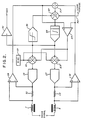
- a servo simulator constructed in accordance with the principles of the invention includes a circuit having components which mimic electrical and mechanical characteristics of an actual servomotor.
- This circuit is a balanced system, typically operating about a l4 volt bias, suitable for simulating a servomotor that may be driven in either direction, depending upon the polarity of the drive signal generated by the autopilot.
- Drive signals from the autopilot are applied through a pair of inductors 7 and 9 having the same inductance as that of an actual servomotor, through resistors ll and l3 equivalent to the resistance of the motor, and then to the output terminals of a pair of power boost amplifiers l5 and l7.
- the output of the amplifiers l5 and l7 simulates the back emf generated in an actual servomotor.
- any amplifier having sufficient bandwidth, drive capacity, and voltage range may be used for the power boost amplifiers.
- these amplifiers may have a frequency bandwidth greater than 25 KHz, a current drive greater than 2 amperes, and an output voltage in the range of l.5 to 26.5 volts in response to a 0-28 volt input signal.
- Input voltages to the amplifiers l5 and l7 are derived from three separate sources.
- the first source is a bias voltage developed in a source l9 applied to the amplifiers through signal combining means 2l and 23 and typically adjusted to be l4 volts.
- the second component of the amplifier input voltages represents motor speed. This component is developed at the output of an integrator 25 and is applied to an addition terminal of combining means 2l and to a subtraction terminal of combining means 23.
- the third component of the amplifier input signal is a current balance signal derived from a differential amplifier 27 and applied to subtraction terminals in the combining means 2l and 23. Input signals to the amplifier 27, in turn, are developed in differential amplifiers 29 and 3l which respond to drive currents flowing through the resistors ll and l3 respectively.
- the drive signal path is through the inductor 7 and resistor ll into the output of the amplifier l5, back out of amplifier l7, resistor l3 and inductor 9.
- Each of the aforementioned resistors represent one-half of a real motor's overall resistance consisting of winding resistance and brush plus commutator block resistance. It can be shown that the torque output of a servomotor is proportional to the motor current. Therefore the sum of the output signals from the amplifiers 29 and 3l are indicative of motor torque.
- the individual torque signals are added in a signal combining circuit 33 and applied to the input terminals of the differential amplifier 27.
- Torque signals from combining circuit 33 are coupled to an addition terminal of signal combining network 37, while a simulated load torque signals from the load simulator 5 ( Figure l) are applied through a conductor 35 to a subtraction input terminal of a signal combining circuit 37.
- This simulated load torque signal mimics the external mechanical forces experienced by an aircraft in flight, such as hinge moment torque arising from aerodynamic surface position, as well as mechanical forces and loads not dependent on control surface positioning.
- signals from a dual slope gain operational amplifier 39 to be described, are applied to a subtraction input terminal of the signal combining circuit 37.
- Output signals from the combining circuit 37 represent the net torque acting on the rotor of an actual servo motor under specified conditions.
- the integrator 25 is designed to have a time constant equivalent to the moment of inertia of the actual servomotor under consideration. Since the signal applied to the integrator from the combining circuit 37 represents net torque, the output voltage of the integrator represents motor speed.
- the motor speed signal is applied to the power boost amplifiers l5 and l7, to a buffer amplifier 4l, as a tachometer signal representative of the motor speed, and to the dual slope gain amplifier 39.
- Amplifier 39 simulates the breakout and coulomb frictions characteristic of an actual servo motor.
- the output of this amplifier is applied in a negative feedback fashion around the integrator and appears to the integrator as a small negative torque signal.
- This torque signal holds the simulated motor speed to near zero until sufficient drive current torque or external load torque signals are applied to overcome the friction torque feedback signal.
- the output signal from the integrator is increased proportionally with motor speed so as to provide additional negative torque feedback to the integrator in order to simulate the effects of coulomb friction experienced in an actual servomotor.
- Figure 3 illustrates a typical load simulator for the servo simulator.
- the motor speed (tach) signal from the servo simulator ( Figure 2) is applied through a rate-adjusting resistor 45 to an integrator 47 to provide a signal which represents the control surface deflection in a real aircraft.
- the rate of integration is controlled by resistor 45 which is adjusted so that this rate is equal to the combined servo gearing and aircraft linkage ratios.
- the resulting deflection signal is buffered by an amplifier 49 and applied to the computer-controlled load wherein the resulting displacement torque ratio or gradient is computed.
- This gradient signal is returned to a multiplier 5l where the gradient signal is multiplied by the surface position signal from the integrator 47.
- the computer also generates a static torque signal which represents forces and load that are not dependent on surface position.
- the static torque signal is applied to a buffer amplifier 53 and applied to a signal combining means 55 together with the output signal from the amplifier 5l.
- the combined output signal is then applied through a buffer amplifier as a load torque signal to the servo simulator of Figure 2.
- the servo simulator of the invention has been described in conjunction with an autopilot and simulated aircraft load, it will be appreciated that the simulator of the invention can be used with any servomechanical control signal source and with other simulated loads.
Landscapes
- Engineering & Computer Science (AREA)
- Computer Hardware Design (AREA)
- Physics & Mathematics (AREA)
- Theoretical Computer Science (AREA)
- Mathematical Physics (AREA)
- General Physics & Mathematics (AREA)
- Control Of Electric Motors In General (AREA)
- Testing Of Devices, Machine Parts, Or Other Structures Thereof (AREA)
- Feedback Control In General (AREA)
Applications Claiming Priority (2)
| Application Number | Priority Date | Filing Date | Title |
|---|---|---|---|
| US06/888,558 US4751443A (en) | 1986-07-22 | 1986-07-22 | Servo simulator |
| US888558 | 1986-07-22 |
Publications (3)
| Publication Number | Publication Date |
|---|---|
| EP0254465A2 true EP0254465A2 (de) | 1988-01-27 |
| EP0254465A3 EP0254465A3 (en) | 1990-05-16 |
| EP0254465B1 EP0254465B1 (de) | 1993-09-29 |
Family
ID=25393403
Family Applications (1)
| Application Number | Title | Priority Date | Filing Date |
|---|---|---|---|
| EP87306189A Expired - Lifetime EP0254465B1 (de) | 1986-07-22 | 1987-07-13 | Servo-Simulator |
Country Status (4)
| Country | Link |
|---|---|
| US (1) | US4751443A (de) |
| EP (1) | EP0254465B1 (de) |
| JP (1) | JPS6334603A (de) |
| DE (1) | DE3787592T2 (de) |
Cited By (1)
| Publication number | Priority date | Publication date | Assignee | Title |
|---|---|---|---|---|
| CN102033201A (zh) * | 2010-10-25 | 2011-04-27 | 广州数控设备有限公司 | 采用交流伺服电机作为可变转矩负载的模拟装置及方法 |
Families Citing this family (13)
| Publication number | Priority date | Publication date | Assignee | Title |
|---|---|---|---|---|
| JP2897030B2 (ja) * | 1989-06-29 | 1999-05-31 | 三菱電機株式会社 | サーボ制御装置 |
| JP2846896B2 (ja) * | 1989-09-08 | 1999-01-13 | 東芝機械株式会社 | Ncサーボシミュレータ |
| JP2954378B2 (ja) * | 1991-04-25 | 1999-09-27 | 三菱電機株式会社 | 電動機サーボ系の制御装置 |
| FR2700026B1 (fr) * | 1992-12-30 | 1995-02-10 | Framatome Sa | Procédé et dispositif de réglage d'un processus. |
| US6002232A (en) * | 1997-08-15 | 1999-12-14 | Iowa State University Research Foundation, Inc. | Robust vibration suppression methods and systems |
| DE102004007295B3 (de) * | 2004-02-14 | 2005-09-29 | Dr.Ing.H.C. F. Porsche Ag | Vorrichtung und Verfahren zur Simulation einer manuellen Bedieneinrichtung |
| DE102005036848B4 (de) * | 2005-08-04 | 2007-11-22 | Siemens Ag | Verfahren und Einrichtung zur Bewegungsführung eines bewegbaren Maschinenelements einer Maschine |
| DE102005048464B4 (de) * | 2005-10-07 | 2014-11-06 | Dspace Digital Signal Processing And Control Engineering Gmbh | Verfahren und Vorrichtung zum Simulieren einer induktiven Last |
| US8108191B1 (en) * | 2005-12-08 | 2012-01-31 | Advanced Testing Technologies, Inc. | Electric motor simulator and method for testing motor driver devices |
| US20080114506A1 (en) * | 2006-11-10 | 2008-05-15 | Davis Christopher L | Hard landing detection |
| DE502008000398D1 (de) * | 2007-10-10 | 2010-04-08 | Silver Atena Electronic System | Verfahren zur Simulation eines Elektromotors oder Generators |
| KR101805348B1 (ko) | 2012-01-18 | 2017-12-06 | 히타치 긴조쿠 가부시키가이샤 | 압분자심, 코일 부품 및 압분자심의 제조 방법 |
| US10481580B2 (en) * | 2014-01-07 | 2019-11-19 | Mitsubishi Electric Corporation | Trajectory control device |
Family Cites Families (5)
| Publication number | Priority date | Publication date | Assignee | Title |
|---|---|---|---|---|
| US3057584A (en) * | 1960-03-01 | 1962-10-09 | Honeywell Regulator Co | Automatic control apparatus |
| US3221229A (en) * | 1962-01-22 | 1965-11-30 | Massachusetts Inst Technology | Model reference adaptive control system |
| US4092716A (en) * | 1975-07-11 | 1978-05-30 | Mcdonnell Douglas Corporation | Control means and method for controlling an object |
| US4500823A (en) * | 1983-02-25 | 1985-02-19 | Westinghouse Electric Corp. | Electro-optical tracking system with adaptive bearing friction compensation |
| US4540923A (en) * | 1984-05-14 | 1985-09-10 | General Motors Corporation | Adaptive servomotor controller |
-
1986
- 1986-07-22 US US06/888,558 patent/US4751443A/en not_active Expired - Fee Related
-
1987
- 1987-07-13 EP EP87306189A patent/EP0254465B1/de not_active Expired - Lifetime
- 1987-07-13 DE DE87306189T patent/DE3787592T2/de not_active Expired - Fee Related
- 1987-07-21 JP JP62182106A patent/JPS6334603A/ja active Pending
Cited By (2)
| Publication number | Priority date | Publication date | Assignee | Title |
|---|---|---|---|---|
| CN102033201A (zh) * | 2010-10-25 | 2011-04-27 | 广州数控设备有限公司 | 采用交流伺服电机作为可变转矩负载的模拟装置及方法 |
| CN102033201B (zh) * | 2010-10-25 | 2012-11-07 | 广州数控设备有限公司 | 采用交流伺服电机作为可变转矩负载的模拟装置及方法 |
Also Published As
| Publication number | Publication date |
|---|---|
| EP0254465B1 (de) | 1993-09-29 |
| EP0254465A3 (en) | 1990-05-16 |
| US4751443A (en) | 1988-06-14 |
| DE3787592T2 (de) | 1994-02-17 |
| DE3787592D1 (en) | 1993-11-04 |
| JPS6334603A (ja) | 1988-02-15 |
Similar Documents
| Publication | Publication Date | Title |
|---|---|---|
| US4751443A (en) | Servo simulator | |
| US4236325A (en) | Simulator control loading inertia compensator | |
| US3220121A (en) | Ground-based flight training or simulating apparatus | |
| US4576577A (en) | Blended mode concept for control of flight simulator motion systems | |
| EP0659640A1 (de) | Aktives Handsteuerungsystem | |
| US3463866A (en) | Flight simulator control loading system | |
| US2814768A (en) | Force balance servosystem | |
| US3031775A (en) | Flight simulator | |
| US4446409A (en) | Electronic controller apparatus | |
| US3007258A (en) | Force simulation | |
| US3114869A (en) | Servo motor speed control system | |
| US4945508A (en) | Process and device for simulating a synchronous electric machine | |
| US3003251A (en) | Jet engine flight temperature characteristics simulator | |
| US2882721A (en) | Simulated inertia weight system | |
| US3824707A (en) | Apparatus for applying simulator g-forces to an arm of an aircraft simulator pilot | |
| US3496651A (en) | Variable force servo-system for control loading | |
| Howe | Fundamentals of the analog computer: circuits, technology, and simulation | |
| JP2846896B2 (ja) | Ncサーボシミュレータ | |
| US2690531A (en) | Electromechanical integrator | |
| US3026629A (en) | Stabilizer trim force simulation | |
| JP2779370B2 (ja) | 電動人工感覚模擬方法及びその装置 | |
| RU2007836C1 (ru) | Способ управления многодвигательным электроприводом | |
| CN115148069B (zh) | 基于动态平衡的大飞机驾驶柱模拟装置及方法 | |
| JPH04175972A (ja) | 回路シミュレーション装置 | |
| Bates et al. | Simulation of massive inertia loads using feedback techniques |
Legal Events
| Date | Code | Title | Description |
|---|---|---|---|
| PUAI | Public reference made under article 153(3) epc to a published international application that has entered the european phase |
Free format text: ORIGINAL CODE: 0009012 |
|
| AK | Designated contracting states |
Kind code of ref document: A2 Designated state(s): DE FR GB IT |
|
| PUAL | Search report despatched |
Free format text: ORIGINAL CODE: 0009013 |
|
| RHK1 | Main classification (correction) |
Ipc: G06G 7/72 |
|
| AK | Designated contracting states |
Kind code of ref document: A3 Designated state(s): DE FR GB IT |
|
| 17P | Request for examination filed |
Effective date: 19901002 |
|
| 17Q | First examination report despatched |
Effective date: 19920702 |
|
| GRAA | (expected) grant |
Free format text: ORIGINAL CODE: 0009210 |
|
| ITF | It: translation for a ep patent filed | ||
| AK | Designated contracting states |
Kind code of ref document: B1 Designated state(s): DE FR GB IT |
|
| REF | Corresponds to: |
Ref document number: 3787592 Country of ref document: DE Date of ref document: 19931104 |
|
| ET | Fr: translation filed | ||
| PGFP | Annual fee paid to national office [announced via postgrant information from national office to epo] |
Ref country code: FR Payment date: 19940614 Year of fee payment: 8 |
|
| PGFP | Annual fee paid to national office [announced via postgrant information from national office to epo] |
Ref country code: GB Payment date: 19940617 Year of fee payment: 8 |
|
| PLBE | No opposition filed within time limit |
Free format text: ORIGINAL CODE: 0009261 |
|
| STAA | Information on the status of an ep patent application or granted ep patent |
Free format text: STATUS: NO OPPOSITION FILED WITHIN TIME LIMIT |
|
| PGFP | Annual fee paid to national office [announced via postgrant information from national office to epo] |
Ref country code: DE Payment date: 19940902 Year of fee payment: 8 |
|
| 26N | No opposition filed | ||
| PG25 | Lapsed in a contracting state [announced via postgrant information from national office to epo] |
Ref country code: GB Effective date: 19950713 |
|
| GBPC | Gb: european patent ceased through non-payment of renewal fee |
Effective date: 19950713 |
|
| PG25 | Lapsed in a contracting state [announced via postgrant information from national office to epo] |
Ref country code: DE Effective date: 19960402 |
|
| PG25 | Lapsed in a contracting state [announced via postgrant information from national office to epo] |
Ref country code: FR Effective date: 19960430 |
|
| REG | Reference to a national code |
Ref country code: FR Ref legal event code: ST |
|
| REG | Reference to a national code |
Ref country code: FR Ref legal event code: ST |
|
| REG | Reference to a national code |
Ref country code: FR Ref legal event code: ST |
|
| PG25 | Lapsed in a contracting state [announced via postgrant information from national office to epo] |
Ref country code: IT Free format text: LAPSE BECAUSE OF NON-PAYMENT OF DUE FEES;WARNING: LAPSES OF ITALIAN PATENTS WITH EFFECTIVE DATE BEFORE 2007 MAY HAVE OCCURRED AT ANY TIME BEFORE 2007. THE CORRECT EFFECTIVE DATE MAY BE DIFFERENT FROM THE ONE RECORDED. Effective date: 20050713 |