EP0253671A2 - Korrosionsschutz - Google Patents
Korrosionsschutz Download PDFInfo
- Publication number
- EP0253671A2 EP0253671A2 EP87306336A EP87306336A EP0253671A2 EP 0253671 A2 EP0253671 A2 EP 0253671A2 EP 87306336 A EP87306336 A EP 87306336A EP 87306336 A EP87306336 A EP 87306336A EP 0253671 A2 EP0253671 A2 EP 0253671A2
- Authority
- EP
- European Patent Office
- Prior art keywords
- anode
- substrate
- electrolyte
- tube
- ion
- Prior art date
- Legal status (The legal status is an assumption and is not a legal conclusion. Google has not performed a legal analysis and makes no representation as to the accuracy of the status listed.)
- Granted
Links
Images

Classifications
-
- C—CHEMISTRY; METALLURGY
- C23—COATING METALLIC MATERIAL; COATING MATERIAL WITH METALLIC MATERIAL; CHEMICAL SURFACE TREATMENT; DIFFUSION TREATMENT OF METALLIC MATERIAL; COATING BY VACUUM EVAPORATION, BY SPUTTERING, BY ION IMPLANTATION OR BY CHEMICAL VAPOUR DEPOSITION, IN GENERAL; INHIBITING CORROSION OF METALLIC MATERIAL OR INCRUSTATION IN GENERAL
- C23F—NON-MECHANICAL REMOVAL OF METALLIC MATERIAL FROM SURFACE; INHIBITING CORROSION OF METALLIC MATERIAL OR INCRUSTATION IN GENERAL; MULTI-STEP PROCESSES FOR SURFACE TREATMENT OF METALLIC MATERIAL INVOLVING AT LEAST ONE PROCESS PROVIDED FOR IN CLASS C23 AND AT LEAST ONE PROCESS COVERED BY SUBCLASS C21D OR C22F OR CLASS C25
- C23F13/00—Inhibiting corrosion of metals by anodic or cathodic protection
- C23F13/02—Inhibiting corrosion of metals by anodic or cathodic protection cathodic; Selection of conditions, parameters or procedures for cathodic protection, e.g. of electrical conditions
- C23F13/04—Controlling or regulating desired parameters
-
- C—CHEMISTRY; METALLURGY
- C23—COATING METALLIC MATERIAL; COATING MATERIAL WITH METALLIC MATERIAL; CHEMICAL SURFACE TREATMENT; DIFFUSION TREATMENT OF METALLIC MATERIAL; COATING BY VACUUM EVAPORATION, BY SPUTTERING, BY ION IMPLANTATION OR BY CHEMICAL VAPOUR DEPOSITION, IN GENERAL; INHIBITING CORROSION OF METALLIC MATERIAL OR INCRUSTATION IN GENERAL
- C23F—NON-MECHANICAL REMOVAL OF METALLIC MATERIAL FROM SURFACE; INHIBITING CORROSION OF METALLIC MATERIAL OR INCRUSTATION IN GENERAL; MULTI-STEP PROCESSES FOR SURFACE TREATMENT OF METALLIC MATERIAL INVOLVING AT LEAST ONE PROCESS PROVIDED FOR IN CLASS C23 AND AT LEAST ONE PROCESS COVERED BY SUBCLASS C21D OR C22F OR CLASS C25
- C23F13/00—Inhibiting corrosion of metals by anodic or cathodic protection
- C23F13/02—Inhibiting corrosion of metals by anodic or cathodic protection cathodic; Selection of conditions, parameters or procedures for cathodic protection, e.g. of electrical conditions
- C23F13/06—Constructional parts, or assemblies of cathodic-protection apparatus
- C23F13/08—Electrodes specially adapted for inhibiting corrosion by cathodic protection; Manufacture thereof; Conducting electric current thereto
- C23F13/16—Electrodes characterised by the combination of the structure and the material
Definitions
- This invention relates to the corrosion protection of pipes, vessels and other corrodible substrates.
- a corrosion-protecting potential difference between the substrate and a counter-electrode.
- a DC power source is used to establish the desired potential difference between the substrate as cathode and an anode which is composed of a material which is resistant to corrosion, eg. platinum, graphite, or a conductive polymer.
- a material which is resistant to corrosion eg. platinum, graphite, or a conductive polymer.
- the known corrosion systems suffer from serious disadvantages, in particular a failure to obtain sufficiently uniform current distribution on the substrate.
- This disadvantage can arise from the use of one or more discrete electrodes; or from the use of a distributed electrode, eg a platinum wire, whose radial resistance to the substrate is low, so that at high currents the current density on the anode decreases rapidly as the distance from the power source increases; and/or because the substrate is shielded (including those situations in which the substrate has a complex shape which results in one part of the substrate being shielded by another part of the substrate).
- the flexible elongate anodes disclosed in U.S. Patents Nos.
- 4,502,929 and 4,473,450 which comprise a low resistance core surrounded by a conductive polymer coating, are very useful in mitigating this disadvantage, but they cannot be used at the high current densities which are required in certain situations, for example the protection of structures which have no protective coating thereon.
- Another disadvantage is the relatively short life of anodes (including the electrical connections thereto), especially when exposed to environments which are highly corrosive or which contain oily contaminants (and in the case of platinum anodes, when exposed to fresh potable water), and the difficulty and expense of repairing or replacing the anodes when this becomes necessary.
- a barrier which lies between the substrate and the counter-electrode, which is spaced part from the substrate and the counter-electrode, and which directs the flow of ions between the substrate and the counter-electrode, and thus provides an improved current distribution on the substrate, and/or enables the counter-electrode to be more easily maintained or replaced, and/or reduces the rate at which the current density on an elongate electrode changes with the distance from the power source, and/or provides a controlled environment around the electrode to improve its efficiency, eg. by reducing contamination or by making it possible to surround the counter-electrode with an electrolyte which is different from the electrolyte which contacts the substrate.
- the present invention provides an assembly for cathodically protecting an electrically conductive substrate from corrosion, and a method of corrosion protection which makes use of such an assembly, the assembly comprising
- the present invention provides a method of cathodically protecting an electrically conductive substrate from corrosion by an electrolyte which contacts it, which method comprises establishing a potential difference between the substrate and a discrete anode which is located in an anode chamber containing an electrolyte and having at least one ion-permeable section therein, the electrolyte being fed into the chamber and being driven by hydrostatic pressure from the chamber through said at least one ion-permeable section.
- the barrier which is used in the present invention modifies the way in which current flows between the substrate and the anode so as to produce one or more of the desirable results noted above. In general, this will result in the resistance between the substrate and the anode being substantially higher than it would be in the absence of the barrier, preferably by a factor of at least l0, for example at least l00, or even more, balancing the resulting advantages against the disadvantage of the higher voltages required as the resistance increases.
- the barrier preferably comprises a plurality of ion-permeable sections.
- Preferred ion-permeable sections include simple apertures, for example a hole in the wall of a tube, or an opening at the end of a tube.
- Ion-permeable sections which are composed of an ion-permeable material, eg. a glass frit, can also be used, especially when it is desired to have the anode contacted by an electrolyte which is different from that which contacts the substrate.
- the size and/or the spacing of the ion-permeable sections can be uniform or non-uniform, depending upon the desired current distribution on the substrate.
- the ion-permeable sections are preferably of fixed dimensions.
- the distance between adjacent ion-permeable sections is preferably less than l0 times, particularly less than 4 times, the distance between the ion-permeable sections and the substrate.
- An important factor in determining the size of the apertures can be the need to ensure that anodic reaction products, eg gaseous chlorine, do not block the apertures. Unless the conditions of operation are such that anodic reaction products remain dissolved in the electrolyte or can be easily vented, care must be taken to prevent harmful build-up of such reaction products between the anode and the barrier. In some case positive benefit can be derived from such reaction products, eg. to lessen fouling of marine structures.
- hydrostatic pressure drives the electrolyte through the ion-permeable section(s) towards the substrate.
- hydrostatic pressure which is typically provided by a pump, can have the alternative and/or additional advantages of (l) reducing the danger that the ion-permeable sections will be blocked by contaminants present in the electrolyte between the barrier and the substrate, for example oily contaminants in the water layer at the bottom of an oil storage tank, and/or (2) making it possible, when it is desired to surround the anode with an electrolyte which is different from the electrolyte which contacts the substrate (eg. when protecting a potable water tank with a platinum anode), to prevent substantial contamination of the anode electrolyte by the substrate electrolyte with minimal contamination of the substrate electrolyte by the anode electrolyte.
- the barrier must not be electronically connected to the substrate or the anode, and is preferably composed of (including coated by) an electrically insulating material, eg. a plastic.
- Preferred barriers are in the form of a tube (which may be of round or other cross section) or a plurality of tubes which are joined together to form a branched structure.
- the branch tubes are preferably of smaller cross-section than the main tube, for example so that the total cross-sectional area of the branch tubes is no greater than the cross-sectional area of the main tube.
- the tube or tubes can be heated by an internal or external heater to reduce the viscosity of the electrolyte therein (including to prevent it from freezing) and/or to reduce its resistivity.
- the tube or tubes can be arranged as a continuous loop, so that electrolyte circulates through them, or can simply terminate in an open end (ie. an ion-permeable section) or a closed end.
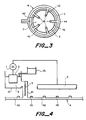
- the tube (or at least one of the tubes where a plurality of tubes are joined together) surrounds an elongate anode, for example one whose length is at least l00 times, preferably at least l000 times, its smallest dimension, typically a metal wire, especially a platinum or platinum-coated wire, having for example a diameter of at least 0.0l inch (0.025 cm), preferably 0.02 to 0.3 inch (0.05 to 0.075 cm).
- the internal diameter of the tube containing the wire anode is preferably P times the diameter of the wire, where P is 2 to l00, eg. 5 to 30, for example a diameter of 0.l25 to 0.6 inch (0.36 to l.5 cm).
- the tube containing the wire anode comprises ion-permeable sections, or there are branch tubes comprising ion-permeable sections attached thereto, or both.
- the branch tubes can comprise perforations and/or can have an open end, which may be fitted with a nozzle. In this way, it is possible to obtain a much more uniform current density on the anode, and hence also on the substrate, than in the absence of the barrier. This desirable result is achieved because the resistance between the substrate and the elongate anode is much greater than it would be in the absence of the tube or tubes, preferably by a factor of at least l0, for example at least l00 or even higher. This is especially valuable when it is desirable to provide a high current from a distributed anode.
- anode comprising a metal core and a conductive polymer jacket, because such anodes cannot support the high current densities required.
- a platinum wire anode or the like; such anodes will support very high current densities, but at the currents needed in such circumstances, the current density on the anode decreases rapidly as the distance from the power source increases, as demonstrated for example in Example 2 below.
- the anode is a discrete electrode which is placed in a vessel remote from the substrate, and electrolyte is pumped (or gravity fed) from the anode vessel to the vicinity of the substrate via one or more tubes which constitute the barrier and which contain (including terminate in) ion-permeable sections.
- the resistivity of the electrolyte is preferably less than 50 ohm.cm, particularly less than 20 ohm.cm, so that the tubes can be of a convenient size.
- the main tube or tubes conveying electrolyte from the anode chamber to the vicinity of the substrate may for example have an equivalent inner diameter (ie. of cross-section equal to a circle of that diameter) of l to l2 inches (2.5 to 30.5 cm), and the branch tubes may for example have an equivalent diameter of 0.5 to 3 inches (l.25 to 7.5 cm).
- the voltage of the power source is preferably less than l00 volts, particularly less than 50 volts, with the system being designed with this preference in mind.
- electrolyte When there is a net transfer of electrolyte through the ion-permeable section(s) of the barrier, electrolyte must be supplied to the anode, and this can be done by recycling electrolyte from the vicinity of the substrate and/or by supplying fresh electrolyte.
- electrolyte When build-up of electrolyte in the vicinity of the substrate must be avoided, eg. in the bottom of an oil storage tank, means must be provided for removing excess electrolyte; the excess electrolyte can be recycled to the anode, if desired or necessary after filtering or otherwise treating it to remove harmful contaminants.
- Preferred uses for the present invention include the protection of city water tanks, ballast tanks in ships, oil rigs, cooling tanks for power stations, water tanks for secondary recovery in oil wells, oil storage tanks, heat exchangers, condensers, heater treaters, and buried pipes, in particular pipes buried below the permafrost line, for example oil pipes in frozen tundra.
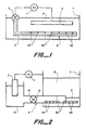
- each of Figures l and 2 shows a DC power source l which is connected to an anode 2 and a corrodible substrate 3 which is a cathode.
- Anode 2 and substrate 3 are separated by a barrier 4 which comprises ion-permeable sections 45, and are connected by electrolyte 5 through sections 45.
- a positive hydrostatic pressure is maintained from the interior of the barrier 4 across the ion-permeable sections 45 by means of pump 6.
- procedure (C) is an example of the invention.
- procedures (A) and (B) are comparative examples and procedure (C) is an example of the invention.
Landscapes
- Chemical & Material Sciences (AREA)
- Engineering & Computer Science (AREA)
- Materials Engineering (AREA)
- Mechanical Engineering (AREA)
- Metallurgy (AREA)
- Organic Chemistry (AREA)
- Prevention Of Electric Corrosion (AREA)
- Preventing Corrosion Or Incrustation Of Metals (AREA)
- Internal Circuitry In Semiconductor Integrated Circuit Devices (AREA)
- Thermistors And Varistors (AREA)
Priority Applications (2)
| Application Number | Priority Date | Filing Date | Title |
|---|---|---|---|
| EP92103118A EP0488995B1 (de) | 1986-07-18 | 1987-07-17 | Korrosionsschutz |
| AT87306336T ATE80674T1 (de) | 1986-07-18 | 1987-07-17 | Korrosionsschutz. |
Applications Claiming Priority (2)
| Application Number | Priority Date | Filing Date | Title |
|---|---|---|---|
| US88819886A | 1986-07-18 | 1986-07-18 | |
| US888198 | 1986-07-18 |
Related Child Applications (1)
| Application Number | Title | Priority Date | Filing Date |
|---|---|---|---|
| EP92103118.3 Division-Into | 1992-02-25 |
Publications (3)
| Publication Number | Publication Date |
|---|---|
| EP0253671A2 true EP0253671A2 (de) | 1988-01-20 |
| EP0253671A3 EP0253671A3 (en) | 1988-08-03 |
| EP0253671B1 EP0253671B1 (de) | 1992-09-16 |
Family
ID=25392719
Family Applications (2)
| Application Number | Title | Priority Date | Filing Date |
|---|---|---|---|
| EP92103118A Expired - Lifetime EP0488995B1 (de) | 1986-07-18 | 1987-07-17 | Korrosionsschutz |
| EP87306336A Expired - Lifetime EP0253671B1 (de) | 1986-07-18 | 1987-07-17 | Korrosionsschutz |
Family Applications Before (1)
| Application Number | Title | Priority Date | Filing Date |
|---|---|---|---|
| EP92103118A Expired - Lifetime EP0488995B1 (de) | 1986-07-18 | 1987-07-17 | Korrosionsschutz |
Country Status (7)
| Country | Link |
|---|---|
| EP (2) | EP0488995B1 (de) |
| JP (1) | JPS6333587A (de) |
| AT (2) | ATE129529T1 (de) |
| CA (1) | CA1331160C (de) |
| DE (2) | DE3781735T2 (de) |
| ES (1) | ES2033852T3 (de) |
| NO (1) | NO177355C (de) |
Cited By (1)
| Publication number | Priority date | Publication date | Assignee | Title |
|---|---|---|---|---|
| GB2296502A (en) * | 1994-12-23 | 1996-07-03 | Cathelco Ltd | Electrolytic descaling ships ballast tanks prior to painting |
Families Citing this family (2)
| Publication number | Priority date | Publication date | Assignee | Title |
|---|---|---|---|---|
| ES2119692B1 (es) * | 1996-07-12 | 1999-05-16 | Lopez Calleja Lopez Jose Luis | Dispositivo, sistema y procedimiento para aislar electricamente la estructura metalica de una embarcacion de una masa externa. |
| DE102014203659A1 (de) * | 2014-02-28 | 2015-09-03 | Siemens Aktiengesellschaft | Kühlvorrichtung für einen Konverter einer Hochspannungs-Gleichstrom-Übertragungsanlage |
Family Cites Families (8)
| Publication number | Priority date | Publication date | Assignee | Title |
|---|---|---|---|---|
| US3022242A (en) * | 1959-01-23 | 1962-02-20 | Engelhard Ind Inc | Anode for cathodic protection systems |
| NL247246A (de) * | 1959-12-17 | 1900-01-01 | ||
| GB1108692A (en) * | 1964-04-17 | 1968-04-03 | Gordon Ian Russell | Method for installing cathodic protection against corrosion |
| NL6612237A (de) * | 1966-08-31 | 1968-03-01 | ||
| JPS5137263B1 (de) * | 1968-10-28 | 1976-10-14 | ||
| US4171254A (en) * | 1976-12-30 | 1979-10-16 | Exxon Research & Engineering Co. | Shielded anodes |
| US4318787A (en) * | 1980-02-22 | 1982-03-09 | Conoco Inc. | Sacrificial anode composition in cathodic protection process |
| US4457821A (en) * | 1983-01-17 | 1984-07-03 | Pennwalt Corporation | Cathodic protection apparatus for well coated metal vessels having a gross bare area |
-
1987
- 1987-07-16 CA CA000542244A patent/CA1331160C/en not_active Expired - Fee Related
- 1987-07-17 EP EP92103118A patent/EP0488995B1/de not_active Expired - Lifetime
- 1987-07-17 AT AT92103118T patent/ATE129529T1/de not_active IP Right Cessation
- 1987-07-17 AT AT87306336T patent/ATE80674T1/de active
- 1987-07-17 DE DE8787306336T patent/DE3781735T2/de not_active Expired - Fee Related
- 1987-07-17 ES ES198787306336T patent/ES2033852T3/es not_active Expired - Lifetime
- 1987-07-17 DE DE3751575T patent/DE3751575T2/de not_active Expired - Fee Related
- 1987-07-17 EP EP87306336A patent/EP0253671B1/de not_active Expired - Lifetime
- 1987-07-17 JP JP62179869A patent/JPS6333587A/ja active Pending
- 1987-07-20 NO NO873015A patent/NO177355C/no unknown
Cited By (1)
| Publication number | Priority date | Publication date | Assignee | Title |
|---|---|---|---|---|
| GB2296502A (en) * | 1994-12-23 | 1996-07-03 | Cathelco Ltd | Electrolytic descaling ships ballast tanks prior to painting |
Also Published As
| Publication number | Publication date |
|---|---|
| NO873015D0 (no) | 1987-07-20 |
| ATE129529T1 (de) | 1995-11-15 |
| EP0488995B1 (de) | 1995-10-25 |
| ES2033852T3 (es) | 1993-04-01 |
| DE3751575D1 (de) | 1995-11-30 |
| NO177355B (no) | 1995-05-22 |
| EP0488995A3 (en) | 1992-07-01 |
| DE3751575T2 (de) | 1996-06-27 |
| DE3781735D1 (de) | 1992-10-22 |
| EP0488995A2 (de) | 1992-06-03 |
| JPS6333587A (ja) | 1988-02-13 |
| EP0253671A3 (en) | 1988-08-03 |
| EP0253671B1 (de) | 1992-09-16 |
| DE3781735T2 (de) | 1993-04-22 |
| ATE80674T1 (de) | 1992-10-15 |
| NO177355C (no) | 1995-09-06 |
| NO873015L (no) | 1988-01-19 |
| CA1331160C (en) | 1994-08-02 |
Similar Documents
| Publication | Publication Date | Title |
|---|---|---|
| US4874487A (en) | Corrosion protection | |
| US4170532A (en) | Deep well platinized anode carrier for cathodic protection system | |
| US3873438A (en) | Electrolytic cell assembly including bipolar concentric electrodes | |
| EP0084875B1 (de) | Lineare Anodenstruktur | |
| EP0796357B1 (de) | Hydrophiles system zur verhinderung der anodischen korrosion | |
| EP0067679B1 (de) | Korrosionsschutzsystem | |
| EP0253671A2 (de) | Korrosionsschutz | |
| CA2010026A1 (en) | Metal mesh and production thereof | |
| US5910236A (en) | Electrodes for electro-chemical corrosion protection systems | |
| CA2245729C (en) | Electrochemical method and electrode | |
| EP1055017A1 (de) | Elektrochemische behandlung von stahlbeton | |
| US4880517A (en) | Catalytic polymer electrode for cathodic protection and cathodic protection system comprising same | |
| GB2175609A (en) | Electrode | |
| US11325168B2 (en) | Dissolving silicate scale | |
| WO1995000984A1 (en) | Apparatus and method for transmission of high voltage direct current | |
| US3691040A (en) | Electrical shield for cathodic protection systems | |
| EP0197981B1 (de) | Katalytische polymerelektrode für katodischen schutz und diese elektrode enthaltendes kathodisches schutzsystem | |
| WO1992016673A1 (en) | Method and arrangement to hinder local corrosion and galvanic corrosion in connection with stainless steels and other passive materials | |
| SU1130621A1 (ru) | Устройство дл защиты от коррозии металлических трубопроводов | |
| Russell et al. | Results through Various Anode System Selections for Cathodic Protection in Natural Waters | |
| NO115621B (de) | ||
| WO1998018981A1 (en) | Electrodes for electro-chemical corrosion protection systems |
Legal Events
| Date | Code | Title | Description |
|---|---|---|---|
| PUAI | Public reference made under article 153(3) epc to a published international application that has entered the european phase |
Free format text: ORIGINAL CODE: 0009012 |
|
| 17P | Request for examination filed |
Effective date: 19870729 |
|
| AK | Designated contracting states |
Kind code of ref document: A2 Designated state(s): AT BE CH DE ES FR GB IT LI NL SE |
|
| PUAL | Search report despatched |
Free format text: ORIGINAL CODE: 0009013 |
|
| AK | Designated contracting states |
Kind code of ref document: A3 Designated state(s): AT BE CH DE ES FR GB IT LI NL SE |
|
| 17Q | First examination report despatched |
Effective date: 19891129 |
|
| GRAA | (expected) grant |
Free format text: ORIGINAL CODE: 0009210 |
|
| AK | Designated contracting states |
Kind code of ref document: B1 Designated state(s): AT BE CH DE ES FR GB IT LI NL SE |
|
| PG25 | Lapsed in a contracting state [announced via postgrant information from national office to epo] |
Ref country code: SE Effective date: 19920916 Ref country code: AT Effective date: 19920916 |
|
| REF | Corresponds to: |
Ref document number: 80674 Country of ref document: AT Date of ref document: 19921015 Kind code of ref document: T |
|
| XX | Miscellaneous (additional remarks) |
Free format text: TEILANMELDUNG 92103118.3 EINGEREICHT AM 17/07/87. |
|
| REF | Corresponds to: |
Ref document number: 3781735 Country of ref document: DE Date of ref document: 19921022 |
|
| ET | Fr: translation filed | ||
| ITF | It: translation for a ep patent filed | ||
| REG | Reference to a national code |
Ref country code: ES Ref legal event code: FG2A Ref document number: 2033852 Country of ref document: ES Kind code of ref document: T3 |
|
| PLBE | No opposition filed within time limit |
Free format text: ORIGINAL CODE: 0009261 |
|
| STAA | Information on the status of an ep patent application or granted ep patent |
Free format text: STATUS: NO OPPOSITION FILED WITHIN TIME LIMIT |
|
| 26N | No opposition filed | ||
| PGFP | Annual fee paid to national office [announced via postgrant information from national office to epo] |
Ref country code: CH Payment date: 19950713 Year of fee payment: 9 |
|
| PGFP | Annual fee paid to national office [announced via postgrant information from national office to epo] |
Ref country code: NL Payment date: 19950727 Year of fee payment: 9 Ref country code: ES Payment date: 19950727 Year of fee payment: 9 |
|
| PGFP | Annual fee paid to national office [announced via postgrant information from national office to epo] |
Ref country code: BE Payment date: 19950911 Year of fee payment: 9 |
|
| PG25 | Lapsed in a contracting state [announced via postgrant information from national office to epo] |
Ref country code: ES Free format text: LAPSE BECAUSE OF NON-PAYMENT OF DUE FEES Effective date: 19960718 |
|
| PG25 | Lapsed in a contracting state [announced via postgrant information from national office to epo] |
Ref country code: LI Effective date: 19960731 Ref country code: CH Effective date: 19960731 Ref country code: BE Effective date: 19960731 |
|
| BERE | Be: lapsed |
Owner name: RAYCHEM CORP. (A CALIFORNIA CORP.) Effective date: 19960731 |
|
| PG25 | Lapsed in a contracting state [announced via postgrant information from national office to epo] |
Ref country code: NL Effective date: 19970201 |
|
| REG | Reference to a national code |
Ref country code: CH Ref legal event code: PL |
|
| NLV4 | Nl: lapsed or anulled due to non-payment of the annual fee |
Effective date: 19970201 |
|
| PGFP | Annual fee paid to national office [announced via postgrant information from national office to epo] |
Ref country code: FR Payment date: 20000711 Year of fee payment: 14 |
|
| PGFP | Annual fee paid to national office [announced via postgrant information from national office to epo] |
Ref country code: GB Payment date: 20000713 Year of fee payment: 14 |
|
| PGFP | Annual fee paid to national office [announced via postgrant information from national office to epo] |
Ref country code: DE Payment date: 20000717 Year of fee payment: 14 |
|
| PG25 | Lapsed in a contracting state [announced via postgrant information from national office to epo] |
Ref country code: GB Free format text: LAPSE BECAUSE OF NON-PAYMENT OF DUE FEES Effective date: 20010717 |
|
| GBPC | Gb: european patent ceased through non-payment of renewal fee |
Effective date: 20010717 |
|
| PG25 | Lapsed in a contracting state [announced via postgrant information from national office to epo] |
Ref country code: FR Free format text: LAPSE BECAUSE OF NON-PAYMENT OF DUE FEES Effective date: 20020329 |
|
| PG25 | Lapsed in a contracting state [announced via postgrant information from national office to epo] |
Ref country code: DE Free format text: LAPSE BECAUSE OF NON-PAYMENT OF DUE FEES Effective date: 20020501 |
|
| REG | Reference to a national code |
Ref country code: FR Ref legal event code: ST |
|
| REG | Reference to a national code |
Ref country code: ES Ref legal event code: FD2A Effective date: 19970811 |
|
| PG25 | Lapsed in a contracting state [announced via postgrant information from national office to epo] |
Ref country code: IT Free format text: LAPSE BECAUSE OF NON-PAYMENT OF DUE FEES;WARNING: LAPSES OF ITALIAN PATENTS WITH EFFECTIVE DATE BEFORE 2007 MAY HAVE OCCURRED AT ANY TIME BEFORE 2007. THE CORRECT EFFECTIVE DATE MAY BE DIFFERENT FROM THE ONE RECORDED. Effective date: 20050717 |