EP0253606A2 - Cathéter thoracique selon Marlin - Google Patents
Cathéter thoracique selon Marlin Download PDFInfo
- Publication number
- EP0253606A2 EP0253606A2 EP87306173A EP87306173A EP0253606A2 EP 0253606 A2 EP0253606 A2 EP 0253606A2 EP 87306173 A EP87306173 A EP 87306173A EP 87306173 A EP87306173 A EP 87306173A EP 0253606 A2 EP0253606 A2 EP 0253606A2
- Authority
- EP
- European Patent Office
- Prior art keywords
- tube
- proximal end
- catheter
- marlin
- rigid rod
- Prior art date
- Legal status (The legal status is an assumption and is not a legal conclusion. Google has not performed a legal analysis and makes no representation as to the accuracy of the status listed.)
- Withdrawn
Links
Images
Classifications
-
- A—HUMAN NECESSITIES
- A61—MEDICAL OR VETERINARY SCIENCE; HYGIENE
- A61M—DEVICES FOR INTRODUCING MEDIA INTO, OR ONTO, THE BODY; DEVICES FOR TRANSDUCING BODY MEDIA OR FOR TAKING MEDIA FROM THE BODY; DEVICES FOR PRODUCING OR ENDING SLEEP OR STUPOR
- A61M25/00—Catheters; Hollow probes
- A61M25/01—Introducing, guiding, advancing, emplacing or holding catheters
- A61M25/06—Body-piercing guide needles or the like
-
- A—HUMAN NECESSITIES
- A61—MEDICAL OR VETERINARY SCIENCE; HYGIENE
- A61M—DEVICES FOR INTRODUCING MEDIA INTO, OR ONTO, THE BODY; DEVICES FOR TRANSDUCING BODY MEDIA OR FOR TAKING MEDIA FROM THE BODY; DEVICES FOR PRODUCING OR ENDING SLEEP OR STUPOR
- A61M1/00—Suction or pumping devices for medical purposes; Devices for carrying-off, for treatment of, or for carrying-over, body-liquids; Drainage systems
- A61M1/84—Drainage tubes; Aspiration tips
-
- A—HUMAN NECESSITIES
- A61—MEDICAL OR VETERINARY SCIENCE; HYGIENE
- A61M—DEVICES FOR INTRODUCING MEDIA INTO, OR ONTO, THE BODY; DEVICES FOR TRANSDUCING BODY MEDIA OR FOR TAKING MEDIA FROM THE BODY; DEVICES FOR PRODUCING OR ENDING SLEEP OR STUPOR
- A61M25/00—Catheters; Hollow probes
- A61M25/0043—Catheters; Hollow probes characterised by structural features
-
- A—HUMAN NECESSITIES
- A61—MEDICAL OR VETERINARY SCIENCE; HYGIENE
- A61M—DEVICES FOR INTRODUCING MEDIA INTO, OR ONTO, THE BODY; DEVICES FOR TRANSDUCING BODY MEDIA OR FOR TAKING MEDIA FROM THE BODY; DEVICES FOR PRODUCING OR ENDING SLEEP OR STUPOR
- A61M2205/00—General characteristics of the apparatus
- A61M2205/02—General characteristics of the apparatus characterised by a particular materials
-
- A—HUMAN NECESSITIES
- A61—MEDICAL OR VETERINARY SCIENCE; HYGIENE
- A61M—DEVICES FOR INTRODUCING MEDIA INTO, OR ONTO, THE BODY; DEVICES FOR TRANSDUCING BODY MEDIA OR FOR TAKING MEDIA FROM THE BODY; DEVICES FOR PRODUCING OR ENDING SLEEP OR STUPOR
- A61M2210/00—Anatomical parts of the body
- A61M2210/10—Trunk
- A61M2210/101—Pleural cavity
Definitions
- This invention relates to a thoracic catheter and, more particularly, to a Marlin thoracic catheter wherein the trocar is formed integral with the catheter.
- Intercostal catheters are used for draining fluids, either gas or liquid, from the thoracic cavity in the operating arena following intrathoracic surgical procedures for post operative drainage, in the emergency room and in various other ambulatory or health care facilities.
- catheters In most surgical procedures wherein an original incision is made, such as in the chest cavity, catheters predominantly have been inserted through an outside body opening from the inside-out.
- the catheter is provided with a distal end and a proximal end.
- the catheter is inserted through the original incision with the proximal end portion entering the incision first.
- a second incision or body opening is made, and a forceps is inserted through the second incision outside-in to grasp the proximal end of the catheter.
- the catheter thereby is pulled through the second incision until the distal end portion is properly positioned with the tube leading out through the second incision.
- the proximal end is connected to an appropriate tubular connector leading to a source of negative pressure to apply suction for draining the body cavity.
- the present invention is directed to providing a new and improved thoracic trocar catheter comprised of a unitary structure which completely eliminates the need for using a separate forceps or separate trocar and in which the catheter itself can be used for piercing body tissue from a-body cavity in an inside-out direction.
- An object, therefore, of the invention is to provide a new and improved, unitary Marlin thoracic catheter.
- a Marlin thoracic catheter generally has a distal end and a proximal end and comprises a tube of flexible material having at least one radial opening at the distal end portion thereof for draining a body cavity.
- Sharpened stiffening means are provided at the proximal end portion of the flexible tube. Pressure can be applied to the stiffened proximal end portion from inside the body cavity to lead the catheter outwardly through body tissue whereupon the sharpened stiffening means can be severed and the catheter left in situ.
- the stiffening means comprises a rigid, preferably solid, rod disposed within and fixed to the inside of the tube at the proximal end portion thereof.
- the rigid rod includes a sharpened or chiseled distal end projecting from the proximal end of the tube.
- the tube may include a fusiform or enlarged portion axially inwardly of the proximal end and tapering toward an opening at the proximal end, the rigid rod being fixed to the tube within the opening.
- the tube may be of substantially uniform diameter with the rigid rod being fixed to the tube within the opening.
- the stiffening means comprises an integral portion of the tube itself. Specifically, a given length of the material of the tube at the proximal end thereof is shaped and hardened to form the stiffening means. The shaped and hardened proximal end of the tube terminates at an angle to sharpen the stiffened tube.
- the tube may include a tapered fusiform or enlarged portion axially inwardly of the proximal end thereof, with the hardened length of the tube extending only partially into the enlarged portion.
- the tube may be a substantially uniform diameter with the shaped and hardened length of the tube extending only partially into and joining with the uniform diameter portion of the tube.
- the rigid rod may be elongated axially outward of the proximal end of the tube and/or inside the proximal end of the tube.
- the material of the rigid rod can be shaped so as to act as a handle for manipulating the rigid rod around the exposed organs in the chest cavity to the site ready for penetration inside-out of the cavity.
- the elongated rigid rod makes it possible to place the tube in difficult places particularly in small chest cavities, such as a child's chest, or in an abnormal chest.
- the portion of the rigid rod in the tube is terminated short of the maximum bulge in the enlarged section of the tube so that the tube, when in place, can be cropped to expose the funnel-shaped opening for a connector without running the risk of severing the rigid rod, thereby creating a loose fragment of said rigid rod, which could be lost within the operative site.
- the present invention in addition to providing a Marlin Thoracic Catheter available at all times for immediate use, provides a significant improvement over the tedious manipulative procedures that were required using forceps placement of a catheter for post-operative drainage.
- the invention completely eliminates the need for a separate incision large enough to accommodate a catheter grasping forceps whose jaws must be opened within a body cavity (i.e. thoracic cavity) in order to grasp a catheter and pull it through the chest wall for proper placement.
- This traditional catheter placement is referenced as the "outside-in method", following the path traversed by the catheter grasping forceps.
- the Marlin Catheter placement is referenced as the "inside-out method", following the path traversed by the penetrating spike, all of which will become apparent from the following description.
- a Marlin thoracic catheter of this invention is inserted through body tissue 12, such as through a thoracic wall between ribs 14 and 16 (intercostal space), in an inside-out direction, as indicated by arrow 18, i.e. from inside a body cavity 20.
- body tissue 12 such as through a thoracic wall between ribs 14 and 16 (intercostal space)
- an inside-out direction as indicated by arrow 18, i.e. from inside a body cavity 20.
- a vein "V”, an artery "A”, and a nerve "N” called a neurovascular bundle is located in a neurovascular space located on the chest cavity side of each rib 14,16 at the narrow inferior edge of the rib.
- the anatomy of the chest wall at the site selected for catheter insertion is normal, injury to the neurovascular bundle can be avoided by inserting the trocar at or near the upper border, thick side, of the rib lying below the intercostal space selected.
- the anatomy of the chest is abnormal, whether due to congenital developmental abnormalities of the blood vessels supplying blood to the chest walls, or if the vascularity of the chest wall is increased by acquired inflammatory or neoplastic disease, the risk of hemorrhage resulting from catheter placement can be minimized by selecting the most favorable site under direct vision and palpation. The superiority of this method in reducing the risk of hemorrhage into the chest cavity is obvious.
- the catheter traverses a direction away from vital structures, as it moves through the various muscle layers encasing the chest wall.
- the usual plan of catheter placement employing a forceps or trocar inserted from the outside starts with the identification of an entry point which will insure that the tract followed by the catheter will pass through the structures of the chest wall, and in many instances upper abdominal muscular layers, so that the catheter energes into the chest wall cavity at a site remote from the entry point at an angle of inclination that insures the catheter will follow the curvature of the internal aspect of the rib cage.
- the portion of the catheter within the chest does not compress the underlying lung tissue or the heart.
- In order to do this safely requires the exercise of powers of depth perception and a clear conception of not only normal anatory but abnormal anatomy of the subject case affecting structures and organs that might be at risk as the forceps or trocar are introduced and advanced.
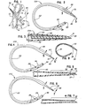
- FIGS 2 and 3 illustrate one embodiment of the invention in the form of a unitary Marlin catheter, generally designated 10A.
- the catheter is flexible and includes a tube portion 22, a distal end portion 24 and a fusiform proximal end portion 26.
- the distal end portion has a series of radial inlet openings 28 and an open distal end 30.
- the proximal end portion 26 is enlarged with a gradual flare to form a bulbous configuration which may be severed at an appropriate location to form a connector as described hereinafter. When severed, the flared proximal end may fit with an appropriate mating connector of varying diameter leading to a source of negative pressure for applying suction to the catheter to withdraw fluids from the body cavity.
- the catheter may be constructed of a seamless, flexible plastic material which is transparent to both light and X-rays although some catheters may have an X-ray opaque line as shown in Sheridan U.S. Patent No. 2,857,915.
- the plastic material is particularly flexuous at body temperatures but is not unduly soft for its function as a catheter. For instance, at body temperature, the tube becomes sufficiently flexuous, as by hand working (i.e. pulling on the catheter tube with a warm hand as the warm hand is drawn or slid along the tube many times) that the catheter can be shaped into the most advantageous configuration for ease in manipulating the catheter in the chest cavity and for locating the trocar end for puncturing an intercostal space in a thoracic wall in an inside-out direction.
- the catheter may be made of any material that is flexible such as rubber or the like.
- the invention contemplate providing sharpened stiffening means unitary with and at the proximal end portion of the catheter whereby pressure can be applied to the stiffened proximal and portion from inside the body cavity to penetrate the stiffened proximal end outwardly through the body tissue.
- the catheter is then worked through the body wall until the distal end is in position whereupon a segment of the bulbous portion is severed to remove the sharpened stiffening means with the catheter left in situ for its intended use.
- the stiffening means for the Marlin thoracic catheter 10A comprises a rigid rod 32 disposed within and fixed to the inside of an open end 31 at the proximal end 2 6 of the tube.
- the rod may be fabricated of plastic material or other material, such as metal, wood, bone, ivory or the like as long as it is considerably more rigid than the material of tube 22.
- the rod is fixed to the tube within opening 31 so as to be unitary or integral therewith, as by heat, ultrasonic welding or other welding methods, or by the use of a solvent or cement at the interface between the tube and rod.
- the rod is sharpened or chiseled, as at"34, at the outer end thereof projecting from the proximal end of the catheter for piercing body tissue.
- the rod extends only a short distance outward of the tube. It is contemplated that the rod could extend outward of the tube an extra distance for specific purposes and procedures.
- the stiffening means or rod 32 may be of a plastic material having the same characteristic of becoming somewhat flexuous at body temperature as does the plastic material of the tube 22 of the catheter 10. For instance, by hand working the tube 22 and rod 32 the rod can be formed into an appropriate shape such as a J shape or the like.
- the stiffening means or rod may be plastic or metal, bone, wood, ivory or the like and may extend all the way or almost all the way through the length of the tube 22 for use in special circumstances.
- an elongate clamp is applied to the rod end of the catheter for remote positioning in the proper place in the chest cavity and then by grasping the remote end of the stiffening means or rod and catheter the trocar end can be forced inside-out through the chest wall.
- tube 22 is cut or severed, as at 36, to simultaneously remove rod 32 and to form a connector.
- the catheter is left in situ ready for draining fluids from the body cavity.
- Figures 4 and 5 show a second embodiment of the invention wherein the stiffening means for a catheter, generally designated 10B, comprises an integral portion of tube 22.
- the tube 22 is of a plastic material and has a given length, such as that indicated at 38, which is hardened to form integral stiffening means for the catheter.
- length 38 does not comprise a flexuous portion of the catheter.
- the given length 38 includes a rod-like portion 31' integrally formed with the tube 26 by a shoulder 44. Since length 38 is made stiff by hardening, the catheter can pierce the body tissue of a patient.
- hardened length 3 8 is formed at an angle, as at 40, to sharpen the hardened, stiffened rod-like end 32' of the catheter. It can be seen that hardened length 38 extends only partially into the enlarged bulbous portion 26 of the catheter whereby the - hardened length can be severed, as at 42, to leave the remainder of the enlarged end flexuous for accommodating connecting means to the source of negative pressure. If the catheter is of substantially uniform diameter, the integral stiffening means can be severed after placement of the catheter whereupon an appropriate suction device is attached for drainage of the site.
- the tubing when made of plastic material, such as polyvinylchloride, is selectively hardened by a leeching process which involves dipping the tubing in a solution such as alcohol.
- the plastic material of the tubing originally is made flexuous by a plasticizer component. Leaching draws out the plasticizer and leaves the tubing hard or stiffened. The degree of hardness depends on the time and temperature parameters of soaking the tubing in the alcohol.
- Figures 6 and 7 show a further embodiment of the invention wherein shoulder 44 (Fig. 5) has been eliminated and the proximal fusiform end of a catheter 10C is provided with a general taper to a sharpened end 46 thereof.
- a given length 48 of the plastic material of the catheter tubing is hardened at the proximal end of the catheter, as by leeching, to form stiffening means to pierce the body tissue. The leeching process also tends to slightly shrink the tubing since the plastic material is being reduced by removing the plasticizer component.
- the stiffening means or rod 32 in the embodiment of Figures 2, 3 and 8 or the hardened tubing in the embodiments of Figures 4-7 acts as a handle for the surgeon to manipulate the Marlin catheter and pierce the body tissue.
- the rod 3 2 runs substantially the greater portion of the length of the catheter so that both the catheter and handle can be grasped simultaneously.
- Figures 9 and 11 show a modified form of Marlin trocar catheter 100 wherein the tube or catheter 122 is substantially the same as the tube or catheter 22 in Figures 2 and 3.
- the rigid rod 132 extends outward from and inwardly into the proximal end 125 of the tube 122 and is fixed and secured thereto.
- the rigid rod 132 has an outwardly exposed spike portion 133 which extends several inches from the proximal end 125 of the tube and has a chisel tip 140 at the end thereof.
- the rod 132 has an inner portion 134 disposed inside the proximal end portion 135 of the tube a short distance and terminates at end 138 short of a high point or mid-portion of the enlarged portion 126 of the tube.
- the tube 122 has radial openings 128 at the distal end portion 124 and has the enlarged bulbous portion 126 near the proximal end 125 of the tube.
- a scoring stripe of paint, or other form of designation indicates a "cut-off" line 137 in the vicinity of the high point of the bulbous portion 1 26 .
- the cut-off line 137 designates where the surgeon should crop the tube 122 after the distal end portion 124 is appropriately placed for suction drainage.
- the rigid rod 132 extends a substantial distance away from the proximal end 125 of the tube.
- the rod including the extended portion can be shaped so as to facility guiding the chiseled or sharpened end 140 through an area where, due to the small size of the chest cavity of the patient or due to a disease of the patient, the rigid rod must be carefully and skillfully maneuvered so as not to cause additional trauma to the patient.
- the rigid rod In testing the catheter, the rigid rod has been extended by as much as 7 1/2" from the proximal end of the tube and has been used successfully to locate the proper exit site and then, by applying pressure to the end 134 of the trocar or rod enclosed in the proximal end portion 135 of the tube, forces the chiseled tip 140 to penetrate the chest wall whereupon by pulling the tube through the incision the distal end of the catheter can be place for drainage.
- the tube 122 is cropped at the cut-off line 137 short of the terminal end 138 of the rigid rod so that the funnel-shaped catheter end can be connected to a connector on an appropriate suction drainage system.
- the rigid rod 132 and part of the proximal end portion 136 of the tube is disposed of.
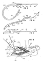
- Figure 10 shows another modified form of a Marlin trocar catheter 200 having a catheter or tube 222 without a bulbous portion in the body of the tube.
- a bulbous portion could be formed in the tube if desired.
- a cut-off line 237 is indicated near the proximal end 225 of the tube. If a bulbous portion were formed in the tube, the cut-off 237 would be approximately midway between the ends of the bulbous portion.
- An elongated rigid rod 232 is fixed or secured in the proximal end portion 235 of the tube with an extended portion or spike 233 of the rod 232 extending outward from the proximal end 225 and an extended portion 231 extending within the tube 222.
- the outer and or spike 233 of the rod has a chisel point 240 for use in penetrating a chest wall.
- the matarial of the rigid rod 232 is such that it is substantially rigid so as to be not only able to transmit forces applied at one end through the rod to the other end but also able to be shaped as desired.
- the end portion 231 of the rod 232 is given an S shape by excessively doubling the rod and tube over at area 239 and at area 241 several times, each time the rod will partially recoil, retaining some degree of bend, eventually the S shape desired is obtained in the rod and tube.
- the S shape provides a handle that can be grasped by the surgeon so that the tube and rod will not turn in the hand.
- the surgeon can guide the rigid rod through the appropriate open spaces between the organs in the chest cavity to the puncture site. Holding the rod using the handle shape provides the surgeon with the purchase needed to push the chisel tip 240 and rod through the appropriate spot in the chest wall. Once the rod penetrates the chest wall, the rod and catheter are pulled through the new puncture opening until the distal drainage end portion 224 is in the proper position whereupon the tube only is cropped at the cut-off line 237 and the rod and part of the proximal end portion 235 of the tube is pulled apart from the rest of the tube and disposed of. Since the rod 232 is relatively rigid, the surgeon can feel when his scalpel engages the rod whereupon he continues cutting the catheter using the rod as a support or backing. In that way, the rod is not severed.
- Figure 12 is an illustration of a chest area 300 of a patient showing two of the improved Marlin trocar catheters 3 02 ,304 in place to drain two different areas of the chest.
- the catheters are of the Figures 9 and 11 variety such that cropping the tube 122 at the cut-off line 137 and discarding the rigid rod 132 and part of the proximal end portion 135 of the catheter makes it possible to attach the appropriate connector and conduit such that suction can be applied to drain the operative site.
- Figure 12 is from the book and the text of the book describes the chest wall triangle 340, delineated in Figure 12 by heavy lines, as an area demarcated by the latissimis dorsi muscle 350, the pectoralis major muscle 352 and the costal arch 354, as the most suitable area for exit of chest tubes, because only one shoulder girdle muscle is traversed, i.e. the Serratus Anterior muscle 356.
- a point of skin exit 358, 360 of the catheter 300, 300 is selected so that the catheter will not be compressed when the patient is lying in bed and so that the catheter passes through the skin with suitable stability to serve as a point for fixation.
- the rigid rod 132 can be given some general shaping that will permit maneuvering the rod 132 through the primary surgical incision to a point selected for penetration of the chisel tip 140 through the lining of the chest cavity, the parietal pleura, and to aim for the site on the patient's skin selected for emergence of the catheter. These sites will determine whether the distal end of the catheter lies anteriorly for drainage of air or posteriorly for drainage of liquid, such as blood.
- the rigid rod 132 is then pulled through from the outside as the drainage tip 124 is guided to the critical location in the thoracic cavity.
- the tube 122 is cropped at the cut-off line 137 whereupon the rigid rod is disposed of and a connector and suction source are connected to the funnel-shaped end of the tube.
- the catheters were not stiff enough to be self-sustaining as an attempt was made to remotely direct or guide the catheter through the anatomical parts in the chest cavity to the outside-in incision through the chest wall. This was particularly true in small chest cavities such as the chest of a child or where the exposed organs in the chest cavity cannot take the pressure caused by a surgeon's hand, all as was detailed hereinabove.
- the improved long spike or elongated rigid rod makes it possible to remotely manipulate the rod or spike tip__and still have sufficient rigidity to penetrate the chest wall under pressure. Elongating the rigid rod into the catheter makes it possible to shape a handle for controlling the manipulations of the rigid rod.
- Providing the rigid rod with an enclosed end that is short of the designated cut-off line provides a safety feature that eliminates the possibility that the trocar or rod will have a free end cropped off and fall loosely into the chest cavity.
Landscapes
- Health & Medical Sciences (AREA)
- Heart & Thoracic Surgery (AREA)
- Life Sciences & Earth Sciences (AREA)
- Engineering & Computer Science (AREA)
- General Health & Medical Sciences (AREA)
- Anesthesiology (AREA)
- Biomedical Technology (AREA)
- Hematology (AREA)
- Veterinary Medicine (AREA)
- Animal Behavior & Ethology (AREA)
- Public Health (AREA)
- Vascular Medicine (AREA)
- Surgery (AREA)
- Biophysics (AREA)
- Pulmonology (AREA)
- Media Introduction/Drainage Providing Device (AREA)
- External Artificial Organs (AREA)
Applications Claiming Priority (6)
| Application Number | Priority Date | Filing Date | Title |
|---|---|---|---|
| US88547786A | 1986-07-14 | 1986-07-14 | |
| US885477 | 1986-07-14 | ||
| US89191986A | 1986-07-30 | 1986-07-30 | |
| US891919 | 1986-07-30 | ||
| US62844 | 1987-06-16 | ||
| US07/062,844 US4883474A (en) | 1986-07-30 | 1987-06-16 | Thoracic catheter |
Publications (2)
| Publication Number | Publication Date |
|---|---|
| EP0253606A2 true EP0253606A2 (fr) | 1988-01-20 |
| EP0253606A3 EP0253606A3 (fr) | 1990-05-02 |
Family
ID=27370380
Family Applications (1)
| Application Number | Title | Priority Date | Filing Date |
|---|---|---|---|
| EP87306173A Withdrawn EP0253606A3 (fr) | 1986-07-14 | 1987-07-13 | Cathéter thoracique selon Marlin |
Country Status (3)
| Country | Link |
|---|---|
| EP (1) | EP0253606A3 (fr) |
| KR (1) | KR890000117A (fr) |
| AU (1) | AU604722B2 (fr) |
Families Citing this family (1)
| Publication number | Priority date | Publication date | Assignee | Title |
|---|---|---|---|---|
| KR100349240B1 (ko) * | 2000-04-08 | 2002-08-19 | 민병무 | 체크 밸브형 흉강 삽관 튜브 |
Citations (6)
| Publication number | Priority date | Publication date | Assignee | Title |
|---|---|---|---|---|
| US3169528A (en) * | 1963-05-24 | 1965-02-16 | Iii Francis S Knox | Coronary sinus sucker |
| US3295527A (en) * | 1964-04-10 | 1967-01-03 | Sheridan Corp | Intercostal catheter |
| FR2024895A1 (fr) * | 1968-11-19 | 1970-09-04 | Prodotti Apparec Clinici | |
| FR2309242A1 (fr) * | 1975-05-02 | 1976-11-26 | Pistor Michel | Nouvel instrument medical formant sonde-aiguille et repartiteur en comportant application |
| US4210479A (en) * | 1978-06-14 | 1980-07-01 | Baxter Travenol Laboratories, Inc. | Method for bonding a plastic tubing to a metal needle and the needle assembly formed thereby |
| US4617019A (en) * | 1984-09-28 | 1986-10-14 | Sherwood Medical Company | Catheter |
Family Cites Families (3)
| Publication number | Priority date | Publication date | Assignee | Title |
|---|---|---|---|---|
| US3584624A (en) * | 1969-02-24 | 1971-06-15 | Vincent L De Ciutiis | Flexible intravenous catheter provided with cutting tip means |
| US4431426A (en) * | 1979-08-20 | 1984-02-14 | Groshong Leroy E | Methods and apparatus for intravenous therapy and hyperalimentation |
| SE428088B (sv) * | 1981-10-14 | 1983-06-06 | Meteve Ab | Troakar |
-
1987
- 1987-07-13 AU AU75588/87A patent/AU604722B2/en not_active Ceased
- 1987-07-13 EP EP87306173A patent/EP0253606A3/fr not_active Withdrawn
- 1987-07-14 KR KR1019870007545A patent/KR890000117A/ko not_active Application Discontinuation
Patent Citations (6)
| Publication number | Priority date | Publication date | Assignee | Title |
|---|---|---|---|---|
| US3169528A (en) * | 1963-05-24 | 1965-02-16 | Iii Francis S Knox | Coronary sinus sucker |
| US3295527A (en) * | 1964-04-10 | 1967-01-03 | Sheridan Corp | Intercostal catheter |
| FR2024895A1 (fr) * | 1968-11-19 | 1970-09-04 | Prodotti Apparec Clinici | |
| FR2309242A1 (fr) * | 1975-05-02 | 1976-11-26 | Pistor Michel | Nouvel instrument medical formant sonde-aiguille et repartiteur en comportant application |
| US4210479A (en) * | 1978-06-14 | 1980-07-01 | Baxter Travenol Laboratories, Inc. | Method for bonding a plastic tubing to a metal needle and the needle assembly formed thereby |
| US4617019A (en) * | 1984-09-28 | 1986-10-14 | Sherwood Medical Company | Catheter |
Also Published As
| Publication number | Publication date |
|---|---|
| AU604722B2 (en) | 1991-01-03 |
| KR890000117A (ko) | 1989-03-11 |
| AU7558887A (en) | 1988-01-21 |
| EP0253606A3 (fr) | 1990-05-02 |
Similar Documents
| Publication | Publication Date | Title |
|---|---|---|
| US4883474A (en) | Thoracic catheter | |
| US7625355B2 (en) | Easy drainage catheter assembly | |
| US7153321B2 (en) | Surgical forceps | |
| JP3110570U (ja) | カテーテル導入器のための固定用ウィング | |
| US5665093A (en) | Surgical implantation method and apparatus | |
| US7981133B2 (en) | Tissue dissection method | |
| US6264670B1 (en) | Tissue dissection method | |
| EP0812571B1 (fr) | Instrument de suture de vaisseaux sanguins | |
| US8486023B2 (en) | Intrathecal catheter having a stylet with a curved tip | |
| EP0539125A1 (fr) | Manipulateur endoscopique de tissu | |
| JP5542771B2 (ja) | 経皮的進入装置及び方法 | |
| US20050273125A1 (en) | Percutaneous vein harvester with shielded blade | |
| WO1994025094A1 (fr) | Appareil destine a placer un catheter sus-pubien (sonde lyell) | |
| EP0652734A1 (fr) | Applicateur de tube d'alimentation pour gastrostomie percutanee et procede associe | |
| JP2002517263A (ja) | カテーテル導入器 | |
| EP0912139A4 (fr) | ||
| JP3233953B2 (ja) | カテーテル装置 | |
| US20090222033A1 (en) | Percutaneous device and method for harvesting tubular body members | |
| EP0253606A2 (fr) | Cathéter thoracique selon Marlin | |
| JPS6373973A (ja) | マ−リン胸部カテ−テル | |
| KR940006623Y1 (ko) | 흉부삽입용 카테타 | |
| CN218636057U (zh) | 医疗穿刺装置 | |
| CN109661205A (zh) | 导管装置、针组件和试剂盒 | |
| JP3038137B2 (ja) | フックプローブ | |
| JPH0736664Y2 (ja) | 逆行性経肝胆道処置用チューブ |
Legal Events
| Date | Code | Title | Description |
|---|---|---|---|
| PUAI | Public reference made under article 153(3) epc to a published international application that has entered the european phase |
Free format text: ORIGINAL CODE: 0009012 |
|
| AK | Designated contracting states |
Kind code of ref document: A2 Designated state(s): AT BE DE ES FR GB GR IT NL SE |
|
| PUAL | Search report despatched |
Free format text: ORIGINAL CODE: 0009013 |
|
| AK | Designated contracting states |
Kind code of ref document: A3 Designated state(s): AT BE DE ES FR GB GR IT NL SE |
|
| 17P | Request for examination filed |
Effective date: 19900612 |
|
| 17Q | First examination report despatched |
Effective date: 19910718 |
|
| STAA | Information on the status of an ep patent application or granted ep patent |
Free format text: STATUS: THE APPLICATION IS DEEMED TO BE WITHDRAWN |
|
| 18D | Application deemed to be withdrawn |
Effective date: 19911129 |