EP0253385A2 - Automatischer Gravitationsfluidumverdichter - Google Patents
Automatischer Gravitationsfluidumverdichter Download PDFInfo
- Publication number
- EP0253385A2 EP0253385A2 EP87110245A EP87110245A EP0253385A2 EP 0253385 A2 EP0253385 A2 EP 0253385A2 EP 87110245 A EP87110245 A EP 87110245A EP 87110245 A EP87110245 A EP 87110245A EP 0253385 A2 EP0253385 A2 EP 0253385A2
- Authority
- EP
- European Patent Office
- Prior art keywords
- vessels
- telescopic
- fluid
- work
- lever
- Prior art date
- Legal status (The legal status is an assumption and is not a legal conclusion. Google has not performed a legal analysis and makes no representation as to the accuracy of the status listed.)
- Withdrawn
Links
Images
Classifications
-
- F—MECHANICAL ENGINEERING; LIGHTING; HEATING; WEAPONS; BLASTING
- F04—POSITIVE - DISPLACEMENT MACHINES FOR LIQUIDS; PUMPS FOR LIQUIDS OR ELASTIC FLUIDS
- F04B—POSITIVE-DISPLACEMENT MACHINES FOR LIQUIDS; PUMPS
- F04B9/00—Piston machines or pumps characterised by the driving or driven means to or from their working members
- F04B9/08—Piston machines or pumps characterised by the driving or driven means to or from their working members the means being fluid
- F04B9/10—Piston machines or pumps characterised by the driving or driven means to or from their working members the means being fluid the fluid being liquid
- F04B9/109—Piston machines or pumps characterised by the driving or driven means to or from their working members the means being fluid the fluid being liquid having plural pumping chambers
- F04B9/111—Piston machines or pumps characterised by the driving or driven means to or from their working members the means being fluid the fluid being liquid having plural pumping chambers with two mechanically connected pumping members
- F04B9/115—Piston machines or pumps characterised by the driving or driven means to or from their working members the means being fluid the fluid being liquid having plural pumping chambers with two mechanically connected pumping members reciprocating movement of the pumping members being obtained by two single-acting liquid motors, each acting in one direction
Definitions
- the invention refers to a fluid compressor device as a generator of big quantities of energetic fluid produced by the potential energy of work bodies in free fall.
- Hydraulic devices which are used for lifting of gates of shipdocks weighting over thousands tons produce large pressure in the local energetic systems.
- the accumulated energy of the fluid inside of its vessels is used during the gate goes down in the no-load periods to drive generators of electric energy, according to which over 90% of the input energy used for lifting of gates is recovered.
- the problem is how to maintain continuous oscillation of the working system with minimum losses of the input energy.
- the invention resides in an automatic gravitational fluid compressor device and an operation process of the kind referred to in the claims l and 4, respectively.
- the main purpose of this device is to make the atmosphere and still water constant and cheap sources for energetic purposes.
- the generally known hydraulic system for lifting of gates of shipdocks is redesigned - according to the present invention - into a new oscillating system serving for conversion of amplified primary energy into secondary output energy.
- the production capacity of the device is solved by big dimensions of compressing elements that can be variously bigger than elements of existing compressors, only because the strokes of work bodies are very slow and the consumption of primary energy is small.
- the security against damage of this system is provided by a suitable disposition of elements of hydraulic vessels which act as shock absorbing springs against eventual hits of work bodies.
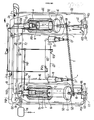
- a lever 5 carrying the work bodies 3,3 ⁇ on the ends thereof and being divided by supports ll and l2 into equal parts of longer and shorter legs is provided.
- the lever 5 is used for connection of both work bodies 3 and 3 ⁇ .
- the system is composed of two hydromechanic semisystems in which the lever 5 is a common part for both systems in such a suitable way that falling weights of the semisystems are used as work bodies 3, 3 ⁇ for compression of secondary fluid in the cylinders l,l ⁇ .
- the smallest consumption of the device is performed in the vessel 20, 20 ⁇ with primary fluid, which are placed between the passive end (A:B) of the lever 5 and a firm bumper 22.
- the final inertial hit of falling weights of work bodies 3, 3 ⁇ is producing hydraulic shocks with a force H in opposite direction to the gravitational force G, approximatively equal to the weight of the falling work bodies on the other side.
- This hydraulic force is produced as an additional pressure in the primary uncompressible fluid to the accumulated energy in the linked vessel from the starting moment of the system work.
- the vessels with the primary fluid are secondary sources of energy which is transmitted from one cycle to another one.
- the secondary source which represents the hydraulic vessels l0, l0 ⁇ , 20, 20 ⁇ .
- Real losses of the semisystem are compensated by the auxiliary source 7 during each cycle.
- Double mechanical hydraulic systems with a tank l4 is used for storing fluid under pressure, which allows a continuous production and consumption of energetic fluid.
- the height of the supports ll, l2 remains constant during the work regime of the semisystem having the work body 3 or 3 ⁇ . The changes are possible only during no load period when the work body is elevating to the potential height.
- the supports ll and l2 as linked vessels are identical in volumes and heights.
- Both ends of the lever 5 are jointly connected on their upper sides by special holders 4 to the telescopic vessels 20, 20 ⁇ . That connection makes it possible for both work bodies 3, 3 ⁇ to have vertical motion in all consecutive positions during work regime.
- work bodies 3, 3 ⁇ Due to increase of their own weight, work bodies 3, 3 ⁇ have enlargements in the upper part of their volumes and their lower diameters.
- the bodies with smaller diameters are used as piston parts. They are placed above the compression vessels l and l ⁇ which are enclosed by cooking vessels 2 and 2 ⁇ , respectively.
- the bumpers 22 are used as limitators of amplitude of the oscillating movement of the ends of the lever 5.
- the telescopic vessels 20 and 20 ⁇ are of smaller cross surface but bigger lenght and are fastened to the bumpers 22, 22 ⁇ .
- the widest parts of the linked vessels l0, l0 ⁇ are connected to supply pipes l8 through the unidirectional valve 30a and 30; 30b.
- the vessels l0 and l0 ⁇ are connected to the vessels 25 and 25 ⁇ through the pipes 24 and 24 ⁇ . But the vessels 25 and 25 ⁇ are connected to the vessel 20 ⁇ through pipes 26 and 26 ⁇ with vessel 20.
- tubular gaskets 8 and 8 ⁇ in form of a ring.
- the mentioned auxiliary source 7 estabilishes the work process of the first semisystem at the start, by filling the vessels l0 and ll with primary fluid under the pressure through the pipe l8 and unidirectional valves 30 and 3l. In that way the said lever is lifted to the necessary height.
- By opening the valve l5a primary fluid under pressure is liberated and flows out through pipe 24 into the upper telescopic vessel 25 which helps pushing the work body 3.
- the work body 3 goes down and changes volume of the cylinder l and compresses secondary fluid until the necessary pressure is reached. That fluid is then pressed out through the tubeline l6 and stored into the collecting tank l4.
- the opening valve l5 liberates primary fluid to flow out from the vessel 20 through the pipe l8a, which flows into the telescopic vessel l0 ⁇ on the other end of the lever 5.
- the secondary fluid is procuded only during the work regime. In the same time the falling bodies produce hydraulic shocks on the passive ends (A or B) of lever, what amplifies primary fluid pressure.
- This invention is suitable for compression of large volumes of secondary energetic fluid with the assistance of primary fluid energy obtained from a special auxiliary source 7 and hydraulic shocks in the primary system.
- Hydraulic pressure from the primary fluid is transmitted into the pressure of secondary fluid, by means of oscillating bodies 3 and 3 ⁇ and their respective vessels l0, l0 ⁇ , 20, 20 ⁇ , 25, 25 ⁇ which represents additional sources of primary energy, oscillating in the system bell-clapper like.
- the essence of the operating process is re-establishment of a definite reserve of energy at the start of the working regime.
- the second condition for the work of that system, with minimum losses, is maintaining the constant reserve of primary energy at the same level during the complete operating process.
- the invention provides two semisystems with independent supports ll and l2 and a common lever 5 with work bodies 3, 3 ⁇ whose oscillation energy produces hydraulic shocks and amplifies it inside of the primary system.
- the hydraulic shocks convert the gravitation force G into a hydraulic force H according to which the pressure of the primary fluid is raised and the losses of the input energy are minimized.
- the fluid compressor decreases the volume many times, but the temperature tends to increase in the same proportion, so that cooling vessels are necessary.
- Very high temperature can produce steam in the closed vessels by the high pressure, which can be used in stationary gas turbines without combustion of fossil fuel.
Landscapes
- Engineering & Computer Science (AREA)
- Mechanical Engineering (AREA)
- General Engineering & Computer Science (AREA)
- Other Liquid Machine Or Engine Such As Wave Power Use (AREA)
- Compressors, Vaccum Pumps And Other Relevant Systems (AREA)
- Reciprocating Pumps (AREA)
Applications Claiming Priority (2)
| Application Number | Priority Date | Filing Date | Title |
|---|---|---|---|
| YU1249/86 | 1986-07-15 | ||
| YU124986 | 1986-07-15 |
Publications (2)
| Publication Number | Publication Date |
|---|---|
| EP0253385A2 true EP0253385A2 (de) | 1988-01-20 |
| EP0253385A3 EP0253385A3 (de) | 1990-04-04 |
Family
ID=25553394
Family Applications (1)
| Application Number | Title | Priority Date | Filing Date |
|---|---|---|---|
| EP87110245A Withdrawn EP0253385A3 (de) | 1986-07-15 | 1987-07-15 | Automatischer Gravitationsfluidumverdichter |
Country Status (1)
| Country | Link |
|---|---|
| EP (1) | EP0253385A3 (de) |
Cited By (1)
| Publication number | Priority date | Publication date | Assignee | Title |
|---|---|---|---|---|
| EP0942170A4 (de) * | 1996-11-26 | 2000-11-08 | Lin Yng Lang | Verdichter für gas |
Family Cites Families (3)
| Publication number | Priority date | Publication date | Assignee | Title |
|---|---|---|---|---|
| DE206737C (de) * | ||||
| US4209990A (en) * | 1978-04-18 | 1980-07-01 | Shelton and Ostrowski Incorporated | Gravity flow hydraulic device |
| DE2909732A1 (de) * | 1979-03-13 | 1980-09-25 | Dieter Schroeter | Hydraulische wasserhebeanlage |
-
1987
- 1987-07-15 EP EP87110245A patent/EP0253385A3/de not_active Withdrawn
Cited By (1)
| Publication number | Priority date | Publication date | Assignee | Title |
|---|---|---|---|---|
| EP0942170A4 (de) * | 1996-11-26 | 2000-11-08 | Lin Yng Lang | Verdichter für gas |
Also Published As
| Publication number | Publication date |
|---|---|
| EP0253385A3 (de) | 1990-04-04 |
Similar Documents
| Publication | Publication Date | Title |
|---|---|---|
| US4466244A (en) | Power generation | |
| US3925986A (en) | Air engine | |
| US5710464A (en) | Power drive system for converting natural potential energy into a driving power to drive a power generator | |
| US8240140B2 (en) | High-efficiency energy-conversion based on fluid expansion and compression | |
| US4317047A (en) | Energy harnessing apparatus | |
| US5094595A (en) | Labrador water-wave energy converter | |
| US7765804B2 (en) | Hydraulic motor using buoyant and gravitational forces to generate kinetic energy | |
| JP5809984B2 (ja) | 加圧ガス駆動コンプレッサおよび当該コンプレッサを備えるシステム | |
| NO151978B (no) | Aggregat for utnyttelse av bevegelsesenergi | |
| JP2009537733A (ja) | 空気圧縮を用いる波エネルギー変換装置(wecwac) | |
| NO771013L (no) | Boelgekraftverk. | |
| US8307642B2 (en) | Hydraulic motor using buoyant and gravitational forces to generate kinetic energy | |
| Ma et al. | Performance investigation of a wave-driven compressed air energy storage system | |
| EP0253385A2 (de) | Automatischer Gravitationsfluidumverdichter | |
| US4497173A (en) | Power transducer system | |
| WO2017118992A1 (en) | Electricity generation through up-down motion of water capsule | |
| CN104863920A (zh) | 一种组合加载油缸 | |
| CN204591859U (zh) | 一种组合加载油缸 | |
| RU2718093C2 (ru) | Система выработки электроэнергии | |
| KR20140004454A (ko) | 공기의 팽창성과 압축성을 이용한 동력발생장치 | |
| CN208364293U (zh) | 一种利用化学能发电的装置 | |
| US1334281A (en) | Storage and utilization of energy by means of liquids | |
| CA1284034C (en) | Recovery hydroelectric power the energy lost in steam condensation | |
| EA021678B1 (ru) | Устройство для получения механической работы от источника нетепловой энергии | |
| WO2025012387A1 (en) | Wave energy converter |
Legal Events
| Date | Code | Title | Description |
|---|---|---|---|
| PUAI | Public reference made under article 153(3) epc to a published international application that has entered the european phase |
Free format text: ORIGINAL CODE: 0009012 |
|
| AK | Designated contracting states |
Kind code of ref document: A2 Designated state(s): AT BE CH DE ES FR GB GR IT LI LU NL SE |
|
| PUAL | Search report despatched |
Free format text: ORIGINAL CODE: 0009013 |
|
| RAP1 | Party data changed (applicant data changed or rights of an application transferred) |
Owner name: CVIJOVIC, IVANKA |
|
| AK | Designated contracting states |
Kind code of ref document: A3 Designated state(s): AT BE CH DE ES FR GB GR IT LI LU NL SE |
|
| STAA | Information on the status of an ep patent application or granted ep patent |
Free format text: STATUS: THE APPLICATION IS DEEMED TO BE WITHDRAWN |
|
| 18D | Application deemed to be withdrawn |
Effective date: 19900201 |