EP0253382B1 - Glueing device for labelling machines - Google Patents
Glueing device for labelling machines Download PDFInfo
- Publication number
- EP0253382B1 EP0253382B1 EP87110241A EP87110241A EP0253382B1 EP 0253382 B1 EP0253382 B1 EP 0253382B1 EP 87110241 A EP87110241 A EP 87110241A EP 87110241 A EP87110241 A EP 87110241A EP 0253382 B1 EP0253382 B1 EP 0253382B1
- Authority
- EP
- European Patent Office
- Prior art keywords
- insert
- glueing
- supporting body
- strip
- glueing device
- Prior art date
- Legal status (The legal status is an assumption and is not a legal conclusion. Google has not performed a legal analysis and makes no representation as to the accuracy of the status listed.)
- Expired - Lifetime
Links
Images


Classifications
-
- B—PERFORMING OPERATIONS; TRANSPORTING
- B65—CONVEYING; PACKING; STORING; HANDLING THIN OR FILAMENTARY MATERIAL
- B65C—LABELLING OR TAGGING MACHINES, APPARATUS, OR PROCESSES
- B65C9/00—Details of labelling machines or apparatus
- B65C9/20—Gluing the labels or articles
- B65C9/22—Gluing the labels or articles by wetting, e.g. by applying liquid glue or a liquid to a dry glue coating
- B65C9/2247—Gluing the labels or articles by wetting, e.g. by applying liquid glue or a liquid to a dry glue coating using liquid rollers or bands
- B65C9/2269—Means for controlling the liquid film on the rollers
-
- B—PERFORMING OPERATIONS; TRANSPORTING
- B65—CONVEYING; PACKING; STORING; HANDLING THIN OR FILAMENTARY MATERIAL
- B65C—LABELLING OR TAGGING MACHINES, APPARATUS, OR PROCESSES
- B65C9/00—Details of labelling machines or apparatus
- B65C2009/0071—Details of glueing devices
- B65C2009/0078—Constructional details of doctor blades
Definitions
- the invention relates to a gluing device for labeling machines according to the preamble of claim 1.
- Glueing devices of this type are known in various designs. They have the important task for a function of the labeling machine to apply the glue in a certain thickness to the glue pallets that take the labels out of the magazine or directly to the labels. Precondition for this is, among other things, an exact setting of the glue strip with regard to the angular position and distance to the glue roller as well as a damage-free, smooth working edge.
- the plate-like glue strip provided with a cutting-shaped working edge is arranged, for example by means of clamping and adjusting screws, on a support which in turn can be pivoted about an axis parallel to the axis of rotation of the glue roller and its angular position can be adjusted by a further adjusting screw (DE-OS 15 86 370).
- a further adjusting screw DE-OS 15 86 370.
- a gluing device in which the glue strip is arranged in a radially displaceable manner in the lower and upper end area relative to the glue roller on a fixed support by means of clamping and adjusting screws (DE-AS 11 11 562).
- the set screws can be used to regulate both the angular position and the distance between the working edge and the glue roller shell. If only the glue film thickness is to be changed, which is more often the case in normal operation, special care must be taken to ensure that the two adjusting screws are turned evenly.
- DE-OS 2 059 234 discloses a glue application device in which a glue strip is formed from a fixedly mounted support and a one-piece, adjustable glue strip body supporting the working edge.
- the parallel alignment of the working edge and the setting of the glue film thickness is carried out by a screw nut, which can be locked in position with the handle equipped with an internal thread.
- a gluing device in which further glue strip pieces are adjustably attached to the pivotable glue strip for the area of the body labels, which determine the glue film thickness for the area of the breast labels or the neck labels (DE-GM 74 35 172).
- the setting of the glue strip for the fuselage labels is carried out in the usual way by a set screw determining their angular position, while the setting of the glue strip pieces for the chest or neck labels compared to the glue strip for the fuselage labels is carried out by means of eccentric bushings and set screws.
- An application device is known from AU-B-477 168, in which a flexible application bar is fixed in its end position within a support body by loose inserting insert sheets. For replacement, both the support body and the insert sheets must be removed.
- the invention has for its object to enable a quick and inexpensive replacement of the working edge in a gluing device of the generic type.
- a gluing device In a gluing device according to the invention, the entire glue strip is no longer exchanged, but only the insert on which the working edge is formed.
- This insert can be of simple shape and relatively narrow and is therefore inexpensive to manufacture.
- the special design of the stop surfaces automatically determines the correct angular position of the working edge or the protrusion with respect to the support body in the newly used insert, so that no readjustment of the support body with respect to the carrier is required.
- the working edge can therefore be exchanged even with slight scoring, which increases the work result of the labeling machine.
- the inserts can be formed with a plurality of working edges, which can be used only by changing their position relative to the support body, without having to be replaced with new tools.
- Common shapes of the inserts form, for example, angular or triangular tools or in the form of a prism, since in all cases it is ensured that parallel stop surfaces are present in addition to the working edges, which are used for secure attachment of the insert to the surfaces of the support body and the clamping plate or the clamping bar.
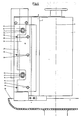
- the gluing device is integrated in a labeling unit for upright bottles (not shown further) and illustrates, in particular according to FIGS. 1 and 4, the vertical block or carrier 1 which can be pivoted about the pin 2 and which is arranged parallel to the axis of rotation 3 of the glue roller 4.
- a support body 5 and an adapted to its shape clamping plate or a clamping bar 6 is adjustably fastened, between whose outwardly projecting, free end regions, the glue strip is clamped by means of screwing.
- the glue strip is designed as an interchangeable insert 8 with a working edge 7, the angular position of which with respect to the support body 5 is determined by rigid stop surfaces 9, 10, 11.
- the working edge 7 of the glue strip or of the insert 8 forms, with the circumference 12 of the glue roller 4, a gap 13 which determines the thickness of the glue film.
- This is caused by a displacement in the arrow directions 14 of the essentially planar contact part 15 of the support body 5 determined and fixed in such a way that 5 elongated hole recesses 16 are arranged in the support body, in which, for example, eccentric disks 18 integrally formed on hexagonal plates 17 protrude flush or form-fitting, which are fixed after the gap 13 has been fixed by means of a central threaded bolt 19 as a counter-screw element.
- Support body 5 and insert 8 extend over the entire height of the glue roller 4, a constant, parallel position between the working edge 7 and the support body 5 being defined by the stop surfaces 9, 10, 11.
- the shape of the insert 8 allows variants such that the insert 8 has the shape of a narrow strip or sheet, which is provided with a working edge 7 on both long sides. This has the particular advantage that the insert can be brought into a new work insert simply by turning, that is to say by changing its position relative to the supporting body 5.
- the shape is not limited to a strip-shaped design of the insert. Viewed in cross-section, this can have the shape of an angled or kinked strip 22, on the two leg ends of which a working edge 20 is provided.
- an insert in the form of a polygon or a triangle 23 or in the form of a prism for proper glue application.
- a secure attachment of the insert 8, 22, 23 in the gluing device is ensured in that it is only releasably clamped to the support body 5 by means of screws, the longitudinal sides of the insert 8, 22, 23 opposite the working edge 7, 20, 21 as rigid stop surfaces 9, 10 and 11 are formed.
- the support body 5 has an essentially flat part 15, which rests on the carrier 1, and an angular part 5a adjoining it laterally, on which the stop surfaces 9, 10 for the insert 8, 22, 23 are flush issue.
- the two angle legs are inclined by approximately 45 degrees with respect to the flat part 15 of the support body 5, so that a type of channel 24 is formed, which is delimited by the insert 8 and in the area of which the adhesive supply or the adhesive circulation, as in FIG. 1 indicated, developed.
- Unnecessary adhesive is collected in the collecting tray 30 underneath and fed to the storage container.
- the clamping plate 6 is adapted to this and has a substantially flat part 25 and an angled part 26 adjoining it laterally, the angular part 26 of the clamping plate 6 engaging in the angled part 5a of the support body 5.
- This arrangement results in a compact design in relation to the two holding elements such as support body 5 and clamping plate 6, the latter having a bend or a bend 27 on its edge opposite the angular part 26 in the direction of the flat part 15 of the support body 5 is supported against a plurality of aligned centering or stop pins 28.
- FIG. 5 A further embodiment of the insert is shown in FIG. 5.
- the insert 30 shown there is a plastic insert which can be produced endlessly as a bar material by means of an extruder.
- the insert 30 has a groove 32 which merges into the working edge 31.
- the purpose of the channel shape is to produce the "glue sausage" with as little resistance as possible, the forces acting on the glue strip being reduced. In addition, the excess glue that accumulates can flow down freely. Despite the trough-shaped cross-section, this plastic insert can be produced cheaply as an extrusion.
- the support body 5 which is designed as a simple plate element, can be adjusted by the eccentric discs 18 (see also description of FIG. 1).
- the clamping plate 6 can take the form of a simple clamping strip.
Description
Die Erfindung betrifft eine Beleimungsvorrichtung für Etikettiermaschinen gemäß dem Oberbegriff des Anspruchs 1.The invention relates to a gluing device for labeling machines according to the preamble of
Derartige Beleimungsvorrichtungen sind in verschiedenen Ausführungen bekannt. Sie haben die für eine Funktion der Etikettiermaschine bedeutsame Aufgabe, den Leim in einer bestimmten Stärke auf die die Etiketten aus dem Magazin entnehmenden Leimpaletten oder direkt auf die Etiketten aufzutragen. Voraussetzung hierfür ist unter anderem eine exakte Einstellung der Leimleiste bezüglich Winkelposition und Abstand zur Leimwalze sowie eine beschädigungsfreie, glatte Arbeitskante.Glueing devices of this type are known in various designs. They have the important task for a function of the labeling machine to apply the glue in a certain thickness to the glue pallets that take the labels out of the magazine or directly to the labels. Precondition for this is, among other things, an exact setting of the glue strip with regard to the angular position and distance to the glue roller as well as a damage-free, smooth working edge.
Bei der am häufigsten verwendeten Beleimungsvorrichtung ist die plattenartige, mit einer schneidenförmigen Arbeitskante versehene Leimleiste z.B. mittels Klemm- und Stellschrauben verstellbar an einem Träger angeordnet, der seinerseits um eine parallel zur Drehachse der Leimwalze stehende Achse schwenkbar und in seiner Winkelposition durch eine weitere Stellschraube justierbar ist (DE-OS 15 86 370). Durch die erstgenannten Klemm- und Stellschrauben ist die Winkelposition sowie der Überstand der Arbeitskante über den Träger, also die sog. Grundeinstellung der Leimleiste, exakt justierbar. Die auf den Träger einwirkende Stellschraube dagegen erlaubt eine schnelle und einfache Anpassung der Leimfilmdicke an die jeweiligen Betriebsbedingungen. In der Grundeinstellung verläuft im allgemeinen die Arbeitskante der Leimleiste exakt parallel zum Mantel der Leimwalze.In the most frequently used gluing device, the plate-like glue strip provided with a cutting-shaped working edge is arranged, for example by means of clamping and adjusting screws, on a support which in turn can be pivoted about an axis parallel to the axis of rotation of the glue roller and its angular position can be adjusted by a further adjusting screw (DE-OS 15 86 370). Thanks to the first-mentioned clamping and adjusting screws, the angular position and the protrusion of the working edge over the carrier, i.e. the so-called basic setting of the glue strip, are exact adjustable. The adjusting screw acting on the carrier, on the other hand, allows the glue film thickness to be adjusted quickly and easily to the respective operating conditions. In the basic setting, the working edge of the glue strip generally runs exactly parallel to the surface of the glue roller.
Verschiedentlich kommt auch noch eine Beleimungseinrichtung zum Einsatz, bei der die Leimleiste mittels Klemm- und Stellschrauben jeweils im unteren und oberen Endbereich radial verschiebbar gegenüber der Leimwalze an einem feststehenden Träger angeordnet ist (DE-AS 11 11 562). Durch die Stellschrauben kann sowohl die Winkelposition als auch der Abstand der Arbeitskante bezüglich des Leimwalzenmantels reguliert werden. Soll nur die Leimfilmdicke geändert werden, was im normalen Betrieb häufiger der Fall ist, so muß besonders auf ein gleichmäßiges Verdrehen der beiden Stellschrauben geachtet werden.Variously, a gluing device is also used, in which the glue strip is arranged in a radially displaceable manner in the lower and upper end area relative to the glue roller on a fixed support by means of clamping and adjusting screws (DE-AS 11 11 562). The set screws can be used to regulate both the angular position and the distance between the working edge and the glue roller shell. If only the glue film thickness is to be changed, which is more often the case in normal operation, special care must be taken to ensure that the two adjusting screws are turned evenly.
In der DE-OS 2 059 234 wird eine Leimauftragsvorrichtung offenbart, bei der eine Leimleiste aus einer ortsfest montierten Stütze und einem einteiligen, einstellbaren, die Arbeitskante tragenden Leimleistenkörper gebildet ist. Die parallele Ausrichtung der Arbeitskante und die Einstellung der Leimfilmstärke erfolgt durch eine Schraubmutter, die in ihrer Stellung durchkontern mit dem mit Innengewinde ausgestatteten Handgriff gesichert werden kann.DE-OS 2 059 234 discloses a glue application device in which a glue strip is formed from a fixedly mounted support and a one-piece, adjustable glue strip body supporting the working edge. The parallel alignment of the working edge and the setting of the glue film thickness is carried out by a screw nut, which can be locked in position with the handle equipped with an internal thread.
Schließlich ist bereits eine Beleimungsvorrichtung bekannt, bei der an der schwenkbaren Leimleiste für den Bereich der Rumpfetiketten weitere Leimleistenstücke verstellbar befestigt sind, die die Leimfilmdicke für den Bereich der Brustetiketten bzw. der Halsetiketten bestimmen (DE-GM 74 35 172). Die Einstellung der Leimleiste für die Rumpfetiketten erfolgt in üblicher Weise durch eine deren Winkelposition bestimmende Stellschraube, während die Einstellung der Leimleistenstücke für die Brust- bzw. Halsetiketten gegenüber der Leimleiste für die Rumpfetiketten durch Exzenterbuchsen und Stellschrauben erfolgt.Finally, a gluing device is already known, in which further glue strip pieces are adjustably attached to the pivotable glue strip for the area of the body labels, which determine the glue film thickness for the area of the breast labels or the neck labels (DE-GM 74 35 172). The setting of the glue strip for the fuselage labels is carried out in the usual way by a set screw determining their angular position, while the setting of the glue strip pieces for the chest or neck labels compared to the glue strip for the fuselage labels is carried out by means of eccentric bushings and set screws.
Ist bei einer der bekannten Beleimungsvorrichtungen die Leimleiste infolge Beschädigungen oder verschleiß an der Arbeitskante unbrauchbar geworden, so muß die Leimleiste als ganzes ausgetauscht und die neu eingesetzte Leimleiste in ihrer Grundstellung exakt justiert werden. Der Austauschvorgang ist somit zeitraubend und die Ersatzteilkosten sind erheblich.If in one of the known gluing devices the glue strip has become unusable due to damage or wear on the working edge, the glue strip must be replaced as a whole and the newly inserted glue strip must be adjusted exactly in its basic position. The exchange process is therefore time-consuming and the spare part costs are considerable.
Aus der AU-B-477 168 ist eine Auftragsvorrichtung bekannt, bei der eine flexible Auftragsteiste innerhalb eines Stützkörpers durch lose einsetzbare Beilageblättchen in ihrer Endlage fixiert ist. Zum Austausch müssen dabei sowohl der Stützkörper als auch die Beilageblättchen entfernt werden.An application device is known from AU-B-477 168, in which a flexible application bar is fixed in its end position within a support body by loose inserting insert sheets. For replacement, both the support body and the insert sheets must be removed.
Der Erfindung liegt die Aufgabe zugrunde, bei einer Beleimungsvorrichtung der gattungsgemäßen Art ein rasches und kostengünstiges Erneuern der Arbeitskante zu ermöglichen.The invention has for its object to enable a quick and inexpensive replacement of the working edge in a gluing device of the generic type.
Diese Aufgabe wird neuerungsgemäß durch die im Kennzeichen des Anspruchs 1 angegebenen Merkmale gelöst.According to the invention, this object is achieved by the features specified in the characterizing part of
Bei einer erfindungsgemäßen Beleimungseinrichtung wird somit nicht mehr die gesamte Leimleiste ausgetauscht, sondern nur noch der Einsatz, an dem die Arbeitskante ausgebildet ist. Dieser Einsatz kann von einfacher Form und relativ schmal sein und ist daher kostengünstig herstellbar. Durch die spezielle Gestaltung der Anschlagflächen wird bei dem neu eingesetzten Einsatz automatisch die richtige Winkelstellung der Arbeitskante bzw. der Überstand gegenüber dem Stützkörper festgelegt, so daß keine Nachjustierung des Stützkörpers gegenüber dem Träger erforderlich ist. Der Austausch der Arbeitskante kann daher schon bei leichter Riefenbildung vorgenommen werden, wodurch sich das Arbeitsergebnis der Etikettiermaschine erhöht. Bei den bekannten Beleimungseinrichtungen dagegen war man aus den vorgenannten Gründen bestrebt, die Leimleiste so lange wie möglich im Einsatz zu lassen.In a gluing device according to the invention, the entire glue strip is no longer exchanged, but only the insert on which the working edge is formed. This insert can be of simple shape and relatively narrow and is therefore inexpensive to manufacture. The special design of the stop surfaces automatically determines the correct angular position of the working edge or the protrusion with respect to the support body in the newly used insert, so that no readjustment of the support body with respect to the carrier is required. The working edge can therefore be exchanged even with slight scoring, which increases the work result of the labeling machine. In the known gluing devices, on the other hand, for the reasons mentioned above, efforts were made to leave the glue strip in use for as long as possible.
Vorteilhafte Weiterbildungen der Erfindung sind in den Unteransprüchen angegeben. Besonders hervorzuheben ist die Ausgestaltung nach den Ansprüchen 4 bis 8, gemäß welchen die Einsätze mit mehreren Arbeitskanten ausgebildet sein können, die lediglich durch eine Veränderung ihrer Lage gegenüber dem Stützkörper wahlweise zum Arbeitseinsatz kommen, ohne daß eine Auswechslung gegen neue Werkzeuge erforderlich ist. Gängige Formgebungen der Einsätze bilden dabei beispielsweise winkelförmige oder dreikantförmige Werkzeuge oder in der Gestalt als Prisma, da in allen Fällen sichergestellt ist, daß neben den Arbeitskanten parallele Anschlagflächen vorhanden sind, die zur sicheren Befestigung des Einsatzes an den Flächen des Stützkörpers und der Klemmplatte bzw. der Spannleiste eng anliegen.Advantageous developments of the invention are specified in the subclaims. Particularly noteworthy is the embodiment according to claims 4 to 8, according to which the inserts can be formed with a plurality of working edges, which can be used only by changing their position relative to the support body, without having to be replaced with new tools. Common shapes of the inserts form, for example, angular or triangular tools or in the form of a prism, since in all cases it is ensured that parallel stop surfaces are present in addition to the working edges, which are used for secure attachment of the insert to the surfaces of the support body and the clamping plate or the clamping bar.
Im nachstehenden werden Ausführungsbeispiele der Erfindung anhand der Zeichnungen beschrieben. Es zeigen, teilweise im Schnitt
- Fig.1
- den Einsatz als schmalen Streifen,
- Fig.2
- den Einsatz in winkelförmiger Ausgestaltung,
- Fig.3
- dgl. in Dreikantausführung,
- Fig.4
- eine Seitenansicht gemäß Fig.1 und
- Fig.5
- den Einsatz in rinnenförmiger Ausgestaltung.
- Fig. 1
- use as a narrow strip,
- Fig. 2
- the use in an angular configuration,
- Fig. 3
- The like in a three-way version,
- Fig. 4
- a side view of Figure 1 and
- Fig. 5
- use in a channel-shaped design.
Die Beleimungsvorrichtung ist in ein nicht weiter dargestelltes Etikettieraggregat für aufrecht stehende Flaschen integriert und veranschaulicht insbesondere nach Fig.1 und 4 den um den Zapfen 2 verschwenkbaren, vertikalen Klotz bzw. Träger 1, welcher parallel zur Drehachse 3 der Leimwalze 4 angeordnet ist. Mit dem Träger 1 ist ein Stützkörper 5 sowie eine an dessen Form angepaßte Klemmplatte bzw. eine Spannleiste 6 verstellbar befestigt, zwischen deren nach außen ragenden, freien Endbereichen die Leimleiste mittels Verschraubung eingeklemmt ist.The gluing device is integrated in a labeling unit for upright bottles (not shown further) and illustrates, in particular according to FIGS. 1 and 4, the vertical block or
Die Leimleiste ist als austauschbarer, eine Arbeitskante 7 aufweisenden Einsatz 8 ausgebildet, dessen Winkelposition in Bezug auf den Stützkörper 5 durch starre Anschlagflächen 9, 10, 11 festgelegt ist.The glue strip is designed as an interchangeable insert 8 with a working edge 7, the angular position of which with respect to the
Die Arbeitskante 7 der Leimleiste bzw. des Einsatzes 8 bildet mit dem Umfang 12 der Leimwalze 4 einen die Leimfilmdicke bestimmenden Spalt 13. Dieser wird durch ein in den Pfeilrichtungen 14 bewirktes Verschieben des im wesentlichen ebenen Anlageteils 15 des Stützkörpers 5 in der Weise bestimmt und fixiert, daß im Stützkörper 5 Langlochausnehmungen 16 angeordnet sind, in welche z.B. an Sechskantplatten 17 angeformte Exzenterscheiben 18 bündig bzw. formschlüssig einragen, die nach Festlegung des Spaltes 13 mittels eines zentrischen Gewindebolzens 19 als Konterschraubelement befestigt werden.The working edge 7 of the glue strip or of the insert 8 forms, with the
Stützkörper 5 und Einsatz 8 erstrecken sich über die gesamte Höhe der Leimwalze 4, wobei eine ständige, parallele Lage zwischen Arbeitskante 7 und Stützkörper 5 durch die Anschlagflächen 9, 10, 11 festgelegt ist. Die Formgebung des Einsatzes 8 läßt Varianten derart zu, daß einmal der Einsatz 8 die Form eines schmalen Streifens oder Blattes aufweist, welcher an beiden Längsseiten mit einer Arbeitskante 7 versehen ist. Dies hat den besonderen Vorteil, daß der Einsatz allein durch Wenden, also durch eine Veränderung dessen Lage gegenüber dem Stützkörper 5 in einen neuen Arbeitseinsatz gebracht werden kann.
Die Formgebung beschränkt sich jedoch nicht auf eine streifenförmige Ausgestaltung des Einsatzes. Dieser kann, im Querschnitt gesehen die Form eines abgewinkelten, bzw. geknickten Streifens 22 aufweisen, an dessen beiden Schenkelenden je eine Arbeitskante 20 vorgesehen ist. Ohne nennenswerte konstruktive Abänderung der Haltevorrichtungen ist es möglich, einen Einsatz in Gestalt eines Mehrkants bzw. eines Dreikants 23 oder in Gestalt eines Prismas für einen ordnungsgemäßen Leimauftrag zu verwenden. Eine sichere Befestigung des Einsatzes 8, 22, 23 in der Beleimungsvorrichtung ist dadurch gewährleistet, daß dieser lediglich mittels Schrauben und zwar lösbar am Stützkörper 5 festgeklemmt ist, wobei die der Arbeitskante 7, 20, 21 gegenüberliegenden Längsseiten des Einsatzes 8, 22, 23 als starre Anschlagflächen 9, 10 bzw. 11 ausgebildet sind. Der Stützkörper 5 weist einen im wesentlichen ebenen Teil 15 auf, der am Träger 1 anliegt, sowie einen sich seitlich daran anschließenden winkelförmigen Teil 5a, an dem die Anschlagflächen 9, 10 für den Einsatz 8, 22, 23 bündig anliegen. Die beiden Winkelschenkel sind gegenüber dem ebenen Teil 15 des Stützkörpers 5 um ca. 45 Grad geneigt, so daß eine Art Rinne 24 entsteht, welche vom Einsatz 8 begrenzt wird und in deren Bereich sich die Klebstoffzuführung bzw. die Klebstoffzirkulation, wie in Fig. 1 angedeutet, entwickelt. Überflüssiger Klebstoff, wird, wie an sich bekannt in der darunter befindlichen Sammelschale 30 aufgefangen und dem Vorratsbehälter zugeführt.However, the shape is not limited to a strip-shaped design of the insert. Viewed in cross-section, this can have the shape of an angled or kinked
Entsprechend der Form des Stützkörpers 5 ist die Klemmplatte 6 diesem angepaßt und weist einen im wesentlichen ebenen Teil 25 und einen sich seitlich daran anschließenden, winkelförmigen Teil 26 auf, wobei der winkelförmige Teil 26 der Klemmplatte 6 in den winkelförmigen Teil 5a des Stützkörpers 5 eingreift. Diese Anordnung ergibt eine kompakte Bauweise in Bezug auf die beiden Halteelemente wie Stützkörper 5 und Klemmplatte 6, wobei die letztere an ihrer dem winkelförmigen Teil 26 gegenüberliegenden Kante in Richtung auf den ebenen Teil 15 des Stützkörpers 5 eine Biegung bzw. eine Abkantung 27 aufweist, die sich gegen mehrere, fluchtende Zentrier- bzw. Anschlagstifte 28 abstützt. Damit ist ein besonders schneller und problemfreier Zusammenbau der Vorrichtung gegeben, da die Befestigung der Klemmplatte bzw. der Spannleiste 6 mit dem Stützkörper 5 lediglich mittels weniger Schrauben 29 erfolgt, deren Gewindebolzen in Gewindebohrungen des Stützkörpers 5 eindringen. Mit dieser Befestigung wird eine die Haltbarkeit der Leimleiste bzw. des Einsatzes 8 fördernde Klemmwirkung an den starren Anschlagflächen 9, 10 und 11 herbeigeführt. Die schneidenförmigen Arbeitskanten 7, 20 und 21 des Einsatzes 8, 22 und 23 ragen bei allen Ausführungsbeispielen gegenüber dem Stützkörper 5 in Richtung auf die Leimwalze 4 hervor; der Einsatz 8, 22 bzw. 23 besteht aus hitzebeständigem Werkstoff. z.B. aus Metall oder aus verschleißfestem Kunststoff.According to the shape of the
Eine weitere Ausgestaltung des Einsatzes ist in Figur 5 dargestellt. Der dort dargestellte Einsatz 30 ist ein Kunststoffeinsatz, der als Stangenmaterial mittels eines Extruders endlos erzeugt werden kann. Der Einsatz 30 weist eine Rinne 32 auf, die in die Arbeitskante 31 übergeht. Die Rinnenform hat den Zweck, eine möglichst widerstandsarme Ausbildung der "Leimwurst" zu erzeugen, wobei die auf die Leimleiste wirkenden Kräfte reduziert werden. Außerdem kann der sich ansammelnde, überschüssige Leim ungehindert nach unten ablaufen. Trotz des rinnenförmigen Querschnitts läßt sich dieser Kunststoffeinsatz als Extrusionsteil billig herstellen. Zur exakt parallelelen Ausrichtung der Arbeitskante 31 bezüglich der Leimwalze kann der als einfaches Plattenelement ausgebildete Stützkörper 5 durch die Exzenterscheiben 18 verstellt werden (siehe auch Beschreibung zur Figur 1). Bei dieser Ausführungsform kann die Klemmplatte 6 die Form einer einfachen Klemmleiste erhalten. Durch Zusammenwirken der Kanten des Stützkörpers 5 und der Klemmplatte 6 mit entsprechenden Absätzen an dem extrudierten Kunststoffeinsatz 30 werden die starren Anschlagflächen 9, 10, 11 festgelegt.A further embodiment of the insert is shown in FIG. 5. The
Claims (19)
- Glueing device for labelling machines, with a rotatable glueing roller and a stationary glueing strip, the working edge of which forms with the circumference of the glueing roller a gap which determines the thickness of the film of glue, wherein the glueing strip is mounted on a carrier so as to be capable of adjustment with respect to the angle to and/or the distance from the wall of the glueing roller, characterised in that the glueing strip comprises a supporting body (5) mounted adjustably on the carrier (1) and an insert (8, 22, 23, 30) which carries the working edge (7, 20, 21, 31) and is mounted interchangeably on the supporting body (5) and of which the angular position with respect to the supporting body (5) is fixed by rigid stop faces (9, 10, 11) existing on the supporting body and cooperating directly with corresponding faces of the insert.
- Clueing device according to claim 1, characterised in that a parallel position of supporting body (5) and insert (8) or working edge (7) is fixed by the stop faces (9, 10, 11).
- Glueing device according to claim 1 or 2, characterised in that the supporting body (5) and insert (8) extend over the full height of the glueing roller (4).
- Glueing device according to any of claims 1 to 3, characterised in that on the insert (8) are formed several parallel working edges (20, 21) which can be brought into operative use optionally by varying the position of the insert relative to the supporting body (5).
- Glueing device according to any of claims 1 to 4, characterised in that the insert (8) has the form of a narrow strip or sheet and is provided with a working edge (7) on at least one longitudinal side (Fig. 1).
- Glueing device according to claim 5, characterised in that the insert (8) as seen in cross-section has the form of a bent or angled strip (22) at the end of each arm of which is provided a working edge (20) (Fig. 2).
- Glueing device according to claim 5, characterised in that the insert (8) as seen in cross-section has the form of a polygon, e.g. a triangle (23) (Fig. 3).
- Glueing device according to claims 5 to 7, characterised in that the longitudinal sides of the insert (8, 22, 23) located opposite the working edge (7, 20, 21) are constructed as rigid stop faces (9, 10, 11).
- Glueing device according to any of claims 1 to 8, characterised in that the insert (8) is releasably fixed to the supporting body (5) by means of screws.
- Glueing device according to claim 9, characterised in that between the screws and the insert (8) is disposed a clamping plate or strip (6) which preferably extends over the whole length of the insert (8).
- Glueing device according to any of claims 1 to 10, characterised in that the supporting body (5) comprises an essentially flat portion (15) which abuts against the carrier (1), and laterally adjoining it an angled portion (5a) on which are formed the stop faces (9, 10) for the insert (8, 22, 23).
- Glueing device according to claim 11, characterised in that the two arms of the angle are each inclined by about 45 degrees to the flat portion (15) of the supporting body (5), so that they form a kind of groove (24) in which the insert (8) sits.
- Glueing device according to any of claims 10 to 12, characterised in that the clamping plate (6), which matches the shape of the supporting body (5), comprises an essentially flat portion (25) and laterally adjoining it an angled portion (26), wherein the angled portion (26) of the clamping plate (6) engages in the angled portion (5a) of the supporting body (5).
- Clueing device according to any of claims 10 to 13, characterised in that the clamping plate or strip (6) comprises, at its edge opposite the angled portion (26), in a direction towards the flat portion (15) of the supporting body (5), a bend or chamfer (27) which is supported on several aligned centring or stop pins (28).
- Glueing device according to any of claims 1 to 14, characterised in that the supporting body (5, 15) comprises slots (16) into which extend in form-locking relationship eccentric washers (18) which are formed integrally on polygonal plates (17) and which can be fixed by means of a threaded bolt (19) as a lock screw.
- Glueing device according to any of claims 1 to 15, characterised in that the insert (8) comprises a blade-like working edge (7) which protrudes from the supporting body (5) in a direction towards the glueing roller (4).
- Glueing device according to claims 1 to 15, characterised in that the insert (8, 20, 23) is made of heat-resistant material, e.g. metal.
- Glueing device according to claims 16 and 17, characterised in that the insert (8, 20, 23) is made of wear-resistant plastic.
- Glueing device according to claim 1, characterised in that the insert is an extruded plastic insert (30) which comprises a groove (32) for banking up and conducting away the resulting string of glue.
Applications Claiming Priority (2)
| Application Number | Priority Date | Filing Date | Title |
|---|---|---|---|
| DE8618988U DE8618988U1 (en) | 1986-07-16 | 1986-07-16 | Gluing device for labeling machines |
| DE8618988U | 1986-07-16 |
Publications (2)
| Publication Number | Publication Date |
|---|---|
| EP0253382A1 EP0253382A1 (en) | 1988-01-20 |
| EP0253382B1 true EP0253382B1 (en) | 1991-10-09 |
Family
ID=6796514
Family Applications (1)
| Application Number | Title | Priority Date | Filing Date |
|---|---|---|---|
| EP87110241A Expired - Lifetime EP0253382B1 (en) | 1986-07-16 | 1987-07-15 | Glueing device for labelling machines |
Country Status (4)
| Country | Link |
|---|---|
| US (1) | US4802440A (en) |
| EP (1) | EP0253382B1 (en) |
| DE (2) | DE8618988U1 (en) |
| ES (1) | ES2001004T3 (en) |
Families Citing this family (7)
| Publication number | Priority date | Publication date | Assignee | Title |
|---|---|---|---|---|
| US5302202A (en) * | 1989-06-13 | 1994-04-12 | Johannes Zimmer | Process and device for applying a coating or substance e.g. adhesive for washing and/or drying an endless conveyor belt or the like |
| DE20220132U1 (en) * | 2002-12-24 | 2004-04-15 | Krones Ag | Adhesive applicator for labelling machine, includes scraper for removing adhesive residue and foreign bodies from roll |
| DE102006017365A1 (en) * | 2006-04-11 | 2007-10-18 | Khs Ag | gluing |
| DE102008038147B4 (en) | 2008-08-18 | 2018-02-15 | Krones Aktiengesellschaft | Gluing device with glue stopper |
| JP2016043488A (en) * | 2014-08-19 | 2016-04-04 | 株式会社Isowa | Pasting device |
| DE102014224440B4 (en) | 2014-11-28 | 2018-02-22 | Töpfer Kulmbach GmbH | Label for application on containers |
| CN112357170A (en) * | 2020-11-27 | 2021-02-12 | 河南中烟工业有限责任公司 | Glue coating lining roller device of YB45 octagonal packaging machine |
Family Cites Families (12)
| Publication number | Priority date | Publication date | Assignee | Title |
|---|---|---|---|---|
| DE7435172U (en) * | 1975-02-06 | Anker Maschinenbau Gmbh | Gluing device for labeling machines | |
| US2754796A (en) * | 1953-09-10 | 1956-07-17 | Rock Hill Printing & Finishing | Design coloring means for fabric material |
| DE1111562B (en) * | 1954-08-20 | 1961-07-20 | Jagenberg Werke Ag | Adhesive application device for labeling machines or the like with an application roller rotating around a vertical axis |
| US3465456A (en) * | 1966-11-18 | 1969-09-09 | Meyer Products Inc | Blade for snowplows and similar devices |
| DE1586370A1 (en) * | 1967-07-22 | 1970-07-30 | Hermann Kronseder | Gluing device |
| DE2059234A1 (en) * | 1970-12-02 | 1972-08-10 | Enzinger Union Werke Ag | Glue application device for labeling machines |
| AU477168B2 (en) * | 1974-08-09 | 1974-11-07 | Ethyl Corporation | Improved metering blade |
| US4315478A (en) * | 1979-05-24 | 1982-02-16 | A-T-O Inc. | Doctor blade for labeling machine |
| DE3300008C2 (en) * | 1982-05-05 | 1984-10-04 | Jagenberg AG, 4000 Düsseldorf | Glue roller for a labeling station |
| DE3369080D1 (en) * | 1982-11-23 | 1987-02-19 | Jagenberg Ag | Apparatus for coating a moving web of material |
| DE8415154U1 (en) * | 1984-05-18 | 1984-09-13 | Jagenberg AG, 4000 Düsseldorf | DEVICE FOR COATING CONTINUOUS MATERIALS |
| US4574417A (en) * | 1984-10-30 | 1986-03-11 | Magnasco Peter L | Scraper |
-
1986
- 1986-07-16 DE DE8618988U patent/DE8618988U1/en not_active Expired
-
1987
- 1987-07-14 US US07/072,903 patent/US4802440A/en not_active Expired - Lifetime
- 1987-07-15 EP EP87110241A patent/EP0253382B1/en not_active Expired - Lifetime
- 1987-07-15 DE DE8787110241T patent/DE3773560D1/en not_active Expired - Lifetime
- 1987-07-15 ES ES198787110241T patent/ES2001004T3/en not_active Expired - Lifetime
Also Published As
| Publication number | Publication date |
|---|---|
| ES2001004A4 (en) | 1988-04-16 |
| EP0253382A1 (en) | 1988-01-20 |
| DE3773560D1 (en) | 1991-11-14 |
| ES2001004T3 (en) | 1992-04-01 |
| DE8618988U1 (en) | 1986-09-11 |
| US4802440A (en) | 1989-02-07 |
Similar Documents
| Publication | Publication Date | Title |
|---|---|---|
| DE3805379C2 (en) | ||
| DE602005002142T2 (en) | INK FEEDING DEVICE FOR PRINTING MACHINE | |
| DE3624754A1 (en) | SCRAPER DEVICE FOR CONVEYOR BELTS | |
| EP0126285B1 (en) | Portable power planer | |
| EP1057597A2 (en) | Device for fixing a flexible cutting die on a cutting cylinder | |
| DE2404291A1 (en) | DOOR HANGER WITH HOLDING DEVICE FOR OPENING | |
| EP0253382B1 (en) | Glueing device for labelling machines | |
| DE3835124A1 (en) | FOLDING MACHINE, IN PARTICULAR FOLDING FOLDING MACHINE | |
| DE3902599C2 (en) | Device for coating a paper web with a coating compound | |
| DE2935426A1 (en) | CUTTING TOOL, e.g. SLOT MILLING OR ROOM NEEDLE | |
| DE4444062A1 (en) | Adjustable alignment device for printing plates | |
| EP0308798B1 (en) | Device to tension flexible printing plates onto the forme cylinder of a rotary printing machine | |
| EP0292758A2 (en) | Attachment for tightening screws with the help of a powerdriven screwdriver | |
| DE3214134A1 (en) | PRINT OR MARKING DEVICE | |
| DE2226245C3 (en) | Cutter head for wood and plastic processing | |
| CH686356A5 (en) | A control device for the ink supply to an offset printing machine. | |
| DE2948744C2 (en) | Device for attaching format plates for exact format transfer of adhesive applications to format rollers | |
| DE2806079C2 (en) | Milling tool with adjustable cutting inserts | |
| DE3703463A1 (en) | CUTTING DEVICE FOR SEPARATING SECTIONS FROM A MOVING MATERIAL STRIP | |
| EP0241765B1 (en) | Labelling machine for containers | |
| DE3611714A1 (en) | Quick-action clamping fastener for attaching spare wheels in a motor vehicle | |
| DE3408354A1 (en) | Profiled cutter head | |
| CH652951A5 (en) | BORING TOOL AND FLATCHING TOOL. | |
| EP0890435A1 (en) | Device for attaching a flexible plate to the surface of a cylinder of a varnishing machine | |
| DE3001330C2 (en) | Exchangeable insert holder for a turning or drilling tool holder |
Legal Events
| Date | Code | Title | Description |
|---|---|---|---|
| PUAI | Public reference made under article 153(3) epc to a published international application that has entered the european phase |
Free format text: ORIGINAL CODE: 0009012 |
|
| AK | Designated contracting states |
Kind code of ref document: A1 Designated state(s): DE ES FR GB IT |
|
| ITCL | It: translation for ep claims filed |
Representative=s name: ING. FRANCO PATRITO |
|
| EL | Fr: translation of claims filed | ||
| 17P | Request for examination filed |
Effective date: 19880630 |
|
| 17Q | First examination report despatched |
Effective date: 19900202 |
|
| GRAA | (expected) grant |
Free format text: ORIGINAL CODE: 0009210 |
|
| ITF | It: translation for a ep patent filed |
Owner name: PATRITO BREVETTI |
|
| AK | Designated contracting states |
Kind code of ref document: B1 Designated state(s): DE ES FR GB IT |
|
| ET | Fr: translation filed | ||
| REF | Corresponds to: |
Ref document number: 3773560 Country of ref document: DE Date of ref document: 19911114 |
|
| GBT | Gb: translation of ep patent filed (gb section 77(6)(a)/1977) | ||
| REG | Reference to a national code |
Ref country code: ES Ref legal event code: FG2A Ref document number: 2001004 Country of ref document: ES Kind code of ref document: T3 |
|
| PLBE | No opposition filed within time limit |
Free format text: ORIGINAL CODE: 0009261 |
|
| STAA | Information on the status of an ep patent application or granted ep patent |
Free format text: STATUS: NO OPPOSITION FILED WITHIN TIME LIMIT |
|
| 26N | No opposition filed | ||
| REG | Reference to a national code |
Ref country code: GB Ref legal event code: IF02 |
|
| PGFP | Annual fee paid to national office [announced via postgrant information from national office to epo] |
Ref country code: GB Payment date: 20050701 Year of fee payment: 19 |
|
| PGFP | Annual fee paid to national office [announced via postgrant information from national office to epo] |
Ref country code: ES Payment date: 20050704 Year of fee payment: 19 |
|
| PGFP | Annual fee paid to national office [announced via postgrant information from national office to epo] |
Ref country code: FR Payment date: 20050713 Year of fee payment: 19 |
|
| PG25 | Lapsed in a contracting state [announced via postgrant information from national office to epo] |
Ref country code: GB Free format text: LAPSE BECAUSE OF NON-PAYMENT OF DUE FEES Effective date: 20060715 |
|
| PGFP | Annual fee paid to national office [announced via postgrant information from national office to epo] |
Ref country code: IT Payment date: 20060731 Year of fee payment: 20 |
|
| PGFP | Annual fee paid to national office [announced via postgrant information from national office to epo] |
Ref country code: DE Payment date: 20060830 Year of fee payment: 20 |
|
| GBPC | Gb: european patent ceased through non-payment of renewal fee |
Effective date: 20060715 |
|
| REG | Reference to a national code |
Ref country code: FR Ref legal event code: ST Effective date: 20070330 |
|
| REG | Reference to a national code |
Ref country code: ES Ref legal event code: FD2A Effective date: 20060717 |
|
| PG25 | Lapsed in a contracting state [announced via postgrant information from national office to epo] |
Ref country code: ES Free format text: LAPSE BECAUSE OF NON-PAYMENT OF DUE FEES Effective date: 20060717 |
|
| PG25 | Lapsed in a contracting state [announced via postgrant information from national office to epo] |
Ref country code: FR Free format text: LAPSE BECAUSE OF NON-PAYMENT OF DUE FEES Effective date: 20060731 |