EP0253102A1 - Storage device for magnetic tape cassettes - Google Patents
Storage device for magnetic tape cassettes Download PDFInfo
- Publication number
- EP0253102A1 EP0253102A1 EP87107372A EP87107372A EP0253102A1 EP 0253102 A1 EP0253102 A1 EP 0253102A1 EP 87107372 A EP87107372 A EP 87107372A EP 87107372 A EP87107372 A EP 87107372A EP 0253102 A1 EP0253102 A1 EP 0253102A1
- Authority
- EP
- European Patent Office
- Prior art keywords
- cassettes
- cassette
- storage container
- magnetic tape
- box
- Prior art date
- Legal status (The legal status is an assumption and is not a legal conclusion. Google has not performed a legal analysis and makes no representation as to the accuracy of the status listed.)
- Withdrawn
Links
- 238000000034 method Methods 0.000 description 1
Images


Classifications
-
- G—PHYSICS
- G11—INFORMATION STORAGE
- G11B—INFORMATION STORAGE BASED ON RELATIVE MOVEMENT BETWEEN RECORD CARRIER AND TRANSDUCER
- G11B23/00—Record carriers not specific to the method of recording or reproducing; Accessories, e.g. containers, specially adapted for co-operation with the recording or reproducing apparatus ; Intermediate mediums; Apparatus or processes specially adapted for their manufacture
- G11B23/02—Containers; Storing means both adapted to cooperate with the recording or reproducing means
- G11B23/023—Containers for magazines or cassettes
- G11B23/0236—Containers for several cassettes
-
- Y—GENERAL TAGGING OF NEW TECHNOLOGICAL DEVELOPMENTS; GENERAL TAGGING OF CROSS-SECTIONAL TECHNOLOGIES SPANNING OVER SEVERAL SECTIONS OF THE IPC; TECHNICAL SUBJECTS COVERED BY FORMER USPC CROSS-REFERENCE ART COLLECTIONS [XRACs] AND DIGESTS
- Y10—TECHNICAL SUBJECTS COVERED BY FORMER USPC
- Y10S—TECHNICAL SUBJECTS COVERED BY FORMER USPC CROSS-REFERENCE ART COLLECTIONS [XRACs] AND DIGESTS
- Y10S206/00—Special receptacle or package
- Y10S206/804—Special receptacle or package with means to lift or draw out content
-
- Y—GENERAL TAGGING OF NEW TECHNOLOGICAL DEVELOPMENTS; GENERAL TAGGING OF CROSS-SECTIONAL TECHNOLOGIES SPANNING OVER SEVERAL SECTIONS OF THE IPC; TECHNICAL SUBJECTS COVERED BY FORMER USPC CROSS-REFERENCE ART COLLECTIONS [XRACs] AND DIGESTS
- Y10—TECHNICAL SUBJECTS COVERED BY FORMER USPC
- Y10S—TECHNICAL SUBJECTS COVERED BY FORMER USPC CROSS-REFERENCE ART COLLECTIONS [XRACs] AND DIGESTS
- Y10S206/00—Special receptacle or package
- Y10S206/817—Follower
Definitions
- the invention relates to a storage container for magnetic tape cassettes or the like according to the preamble of the main claim.
- Storage containers of this type are used today primarily for CD cassettes, magnetic tape cassettes or the like. They are used to hold these cassettes in cars or other vehicles, but also in the home. For example, spring-loaded drawers or slides are used to hold these cassettes.
- spring-loaded drawers or slides are used to hold these cassettes.
- cassettes are inserted into a storage container designed as a box, be it lying or standing, without tools, it is very difficult for the user to remove a specific cassette from the box, since there is usually not enough space between the cassettes as an access area .
- the inventor's goal is to create an up To develop storage containers of the type mentioned above, which does not require drawers or the like for holding the cassettes and in which the cassettes or the box itself does not have to have any special cutouts, recessed walls or the like as an access area.
- a storage container in particular for magnetic tape cassettes, consists of a cuboid box 1 with an open front 2. This front can of course be closed by a cover (not shown in more detail).
- the cassettes 3 shown in the exemplary embodiments are arranged in the box 1 either standing (see FIG. 1) or lying (see FIG. 2).
- retaining webs 6 protrude from a floor 4 and opposite from a ceiling 5 into the interior I of the box 1. Furthermore, in the floor area a skirting board 7 extends transversely to the holding webs 6 and the cassettes 3 strike against it.
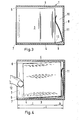
- FIGS. 3 and 4 show that an upward slope 9 is located towards the rear wall 8 of the box 1.
- the slope 9 has a width b, which corresponds to the depth t of the box 1 minus the cassette length 1 corresponds.
- a space 10 is formed behind the cassettes 3, in which a spring 11 which projects from the bevel 9 and which is supported against the cassettes 3 engages.
- this spring 11 presses the cassette 3 against the baseboard 7, whereby the cassette is held in the box 1. If a cassette is now to be removed from adjacent cassettes 3, the cassettes standing next to the cassette to be removed can be pressed backwards against the force of the spring by means of the gripping fingers 12 (see FIG. 4) and the cassette to be removed is exposed. When this cassette is pulled out, the cassettes pushed back by the gripping fingers 12 follow to the baseboard 7 and then remain in the box 1.
- the embodiment with the spring 11 should only be considered as preferred.
- the arrangement of the bevel 9 is sufficient, and in a further exemplary embodiment this can also extend from the rear wall 8 of the box 1 to the baseboard 7 without forming a bend 13 in between.
- the slope 9 is designed so that the cassettes 3 slide forward by their own weight, that is, the slope accordingly.
- the cassettes 3 are arranged horizontally.
- the side walls 15 of the box 1 serve to hold them in place, formed with guide strips 16 which have a raised edge 17 towards the front 2. This edge 17 is comparable to the baseboard 7.
- the guide strips 16 run in one Winkela to the bottom 4 of the box 1. This in turn creates a sliding surface for the cassettes 3, which abut the edge 17 in the transport position.
- the guide strips 16 are provided with a bevel 18 towards the rear wall 8 of the box 1, forming a bend 19, which is comparable to the bevel 9.
- springs 20 projecting from the rear wall 8 are schematically indicated, which hold the cassettes 3 in contact with the edge 17.
Abstract
Es wird ein Aufbewahrungsbehälter für Magnetbandkassetten (3) oder dgl. angegeben, der mehrere Kassetten stehend oder liegend enthält und im Zugriffsbereich zwischen den Kassetten einen Freiraum hat. Erfindungsgemäss ist vorgesehen, dass jede Kassette (3) unabhängig von den übrigen Kassetten in das Innere des Aufbewahrungsbehälters einschiebbar ist und selbsttätig nach vorne gegen einen vorderen Anschlag (17) zurückgeschoben wird. Soll eine bestimmte Kassette (3) ergriffen werden, so werden dabei die beiden benachbarten Kassetten beim Zugreifen mit den Fingern (12) zurückgeschoben und gleiten nach der Entnahme der Kassette wieder in ihre Ausgangsstellung zurück.A storage container for magnetic tape cassettes (3) or the like is specified which contains several cassettes standing or lying and has a free space in the access area between the cassettes. According to the invention, each cassette (3) can be pushed into the interior of the storage container independently of the other cassettes and is automatically pushed forward against a front stop (17). If a specific cassette (3) is to be gripped, the two adjacent cassettes are pushed back with the fingers (12) when they are accessed and slide back into their starting position after the cassette has been removed.
Description
Die Erfindung betrifft einen Aufbewahrungsbehälter für Magnetbandkassetten oder dergleichen gemäß der Gattung des Hauptanspruchs.The invention relates to a storage container for magnetic tape cassettes or the like according to the preamble of the main claim.
Derartige Aufbewahrungsbehälter finden heute vor allem für CD-Kassetten, Magnetbandkassetten oder dergleichen Anwendung. Sie werden zur Halterung dieser Kassetten in Autos oder anderen Fahrzeugen aber auch im Heimbereich verwendet. Zur Aufnahme dieser Kassetten dienen beispielsweise federgelagerte Schubladen oder Schieber. Werden jedoch Kassetten ohne Hilfsmittel in einen als Box ausgebildeten Aufbewahrungsbehälter eingelegt, sei es liegend oder stehend, bereitet es dem Benutzer erhebliche Schwierigkeiten, eine bestimmte Kassette wieder aus der Box zu entnehmen, da in der Regel kein genügend großer Freiraum zwischen den Kassetten als Zugriffsbereich entsteht.Storage containers of this type are used today primarily for CD cassettes, magnetic tape cassettes or the like. They are used to hold these cassettes in cars or other vehicles, but also in the home. For example, spring-loaded drawers or slides are used to hold these cassettes. However, if cassettes are inserted into a storage container designed as a box, be it lying or standing, without tools, it is very difficult for the user to remove a specific cassette from the box, since there is usually not enough space between the cassettes as an access area .
Der Erfinder hat sich zum Ziel gesetzt, einen Aufbewahrungsbehälter der obengenannten Art zu entwickeln, welcher ohne Schubladen oder dergleichen für die Halterung der Kassetten auskommt und bei dem die Kassetten bzw. die Box selber keine speziellen Aussparungen, zurückgesetzte Wände oder dergleichen als Zugriffsbereich aufweisen muß.The inventor's goal is to create an up To develop storage containers of the type mentioned above, which does not require drawers or the like for holding the cassettes and in which the cassettes or the box itself does not have to have any special cutouts, recessed walls or the like as an access area.
Die Lösung dieser Aufgabe erhält man durch die im Hauptanspruch angegebenen Merkmale. Dadurch, daß zwischen den Kassetten ein Freiraum besteht, ist es möglich, bei Zugriff zu einer Kassette, die benachbarten Kassetten gleichzeitig mit den Figern zurückzuschieben, so daß die gewünschte Kassette problemlos ergriffen werden kann. Als Einrichtungen, die die Kassetten gegen vordere Anschläge schieben, können Schrägen und/oder geneigte Auflageflächen vorgesehen sein, wodurch die Kassetten selbsttätig gegen die vorderen Anschläge gleiten. Bevorzugt ist jedoch, im Bereich der Rückseite der Kassetten Federn oder entsprechende Vorschubeinrichtungen zu verwenden, mit Hilfe derer die Kassetten gegen die Anschläge gedrückt werden. Bei der Entnahme einer Kassette wird diese etwas angehoben, so daß die als Anschlag ausgebildete vordere Kante bzw. Fußleiste überwunden wird. Die benachbarten Kassetten gleiten dann beim Herausziehen der Kassette wieder in ihre ursprüngliche Lage.The solution to this problem is obtained by the features specified in the main claim. The fact that there is a space between the cassettes, it is possible, when accessing a cassette, to push the neighboring cassettes back together with the figures, so that the desired cassette can be gripped without problems. As devices that push the cassettes against front stops, bevels and / or inclined contact surfaces can be provided, as a result of which the cassettes slide automatically against the front stops. However, it is preferred to use springs or corresponding feed devices in the area of the rear of the cassettes, by means of which the cassettes are pressed against the stops. When a cassette is removed, it is raised slightly so that the front edge or baseboard designed as a stop is overcome. The adjacent cassettes then slide back into their original position when the cassette is pulled out.
Weitere vorteilhafte Merkmale und Einzelheiten der Erfindung ergeben sich aus der nachfolgenden Beschreibung bevorzugter Ausführungsbeispiele sowie anhand der Zeichnung; diese zeigt in
Figur 1 eine perspektivische Ansicht eines Aufbewahrungsbehälters für beispielsweise Magnetbandkassetten;Figur 2 eine perspektivische Ansicht eines weiteren Ausführungsbeispiels eines Aufbewahrungsbehälters nachFigur 1;Figur 3 einen Querschnitt durch den Aufbewahrungsbehälter nachFigur 1 entlang Linie III - III;Figur 4 einen Querschnittentsprechend Figur 3, jedoch während der Entnahme einer Kassette;Figur 5 einen Querschnitt durch den Aufbewahrungsbehälter nachFigur 2 entlang Linie V - V; jedoch mit zwei Kassetten und 5 Lagerstegen;Figur 6 einen Querschnitt durch ein weiteres Ausführungsbeispiel eines Aufbewahrungsbehälters entsprechendFigur 2 entlang Linie V - V.
- Figure 1 is a perspective view of a storage container for example magnetic tape cassettes;
- Figure 2 is a perspective view of another embodiment of a storage container according to Figure 1;
- 3 shows a cross section through the storage container according to Figure 1 along line III - III;
- FIG. 4 shows a cross section corresponding to FIG. 3, but during the removal of a cassette;
- 5 shows a cross section through the storage container according to FIG. 2 along line V-V; however with two cassettes and 5 ramps;
- FIG. 6 shows a cross section through a further exemplary embodiment of a storage container corresponding to FIG. 2 along line V - V.
Ein Aufbewahrungsbehälter, insbesondere für Magnetbandkassetten, besteht nach den Figuren 1 und 2 aus einer quaderförmigen Box 1 mit einer offenen Front 2. Diese Front kann selbstverständlich durch einen nicht näher gezeigten Deckel verschlossen sein.According to FIGS. 1 and 2, a storage container, in particular for magnetic tape cassettes, consists of a
Die in den Ausführungsbeispielen gezeigten Kassetten 3 sind in der Box 1 entweder stehend (siehe Figur 1) oder liegend (siehe Figur 2) angeordnet.The
Bei den stehend angeordneten Kassetten 3 ragen von einem Boden 4 und gegenüberliegend von einer Decke 5 Haltestege 6 in den Innenraum I der Box 1 ein. Weiterhin ragt im Bodenbereich eine quer zu den Haltestegen 6 verlaufende Fußleiste 7 auf, an welcher die Kassetten 3 anschlagen.In the case of the
In den Figuren 3 und 4 ist gezeigt, daß zur Rückwand 8 der Box 1 hin eine sich hochziehende Schräge 9 befindet. Die Schräge 9 hat eine Breite b, welche der Tiefe t der Box 1 vermindert um die Kassettenlänge 1 entspricht. Hierdurch ist hinter den Kassetten 3 ein Raum 10 ausgebildet, in welchen eine von der Schräge 9 aufragende Feder 11 eingreift, die sich gegen die Kassetten 3 abstützt.FIGS. 3 and 4 show that an
In Ruhelage drückt diese Feder 11 die Kassette 3 gegen die Fußleiste 7, wodurch die Kassette in der Box 1 gehalten wird. Soll nun bei nebeneinanderstehenden Kassetten 3 eine Kassette entnommen werden, so können die neben der zu entnehmenden Kassette stehenden Kassetten mittels der Greiffinger 12 (siehe Figur 4) gegen die Kraft der Feder nach hinten gedrückt werden und die zu entnehmende Kassette wird freigelegt. Biem Herausziehen dieser Kassette folgen die von den Greiffingern 12 nach hinten gedrückten Kassetten bis zur Fußleiste 7 und verbleiben sodann in der Box 1.In the rest position, this
Das Ausführungsbeispiel mit der Feder 11 soll nur als bevorzugt betrachtet werden. In einer einfacheren Ausgestaltung der Erfindung genügt alleine die Anordnung der Schräge 9, wobei sich diese in einem weiteren Ausführungsbeispiel auch von der Rückwand 8 der Box 1 bis zur Fußleiste 7 erstrecken kann, ohne dazwischen einen Knick 13 auszubilden. Die Schräge 9 ist so ausgestaltet, daß die Kassetten 3 durch ihr Eigengewicht nach vorne, also der Schräge entsprechend nach unten gleiten.The embodiment with the
Bei dem Ausführungsbeispiel der Box 1 gemäß Figur 2 sind die Kassetten 3 liegend angeordnet. Zu ihrer Halterung dienen die Seitenwände 15 der Box 1 angeformte Führungsleisten 16, welche zur Front 2 hin eine hochgezogene Kante 17 aufweisen. Diese Kante 17 ist vergleichbar mit der Fußleiste 7.In the exemplary embodiment of
Gemäß Figur 5 verlaufen die Führungsleisten 16 in einem Winkela zum Boden 4 der Box 1. Hierdurch wird wiederum eine Gleitfläche für die Kassetten 3 erzeugt, die in Transportlage an der Kante 17 anschlagen.According to FIG. 5, the
Gemäß Figur 6 sind die Führungsleisten 16 zur Rückwand 8 der Box 1 hin unter Ausbildung eines Knickes 19 mit einer Schräge 18 versehen, welche mit der Schräge 9 vergleichbar ist.According to FIG. 6, the
Weiterhin sind von der Rückwand 8 abragende Federn 20 schematisch angedeutet,welche die Kassetten 3 in Anschlag mit der Kante 17 halten.Furthermore,
Der Entnahmevorgang einer gewünschten Kassette ist ähnlich wie oben beschrieben. Durch das Eingreifen in die Box werden die beiden benachbarten Kassetten 3, eventuell gegen die Kraft ihrer zugeordneten Federn 20 zur Rück- wand 8 hin verschoben, so daß die zu entnehmende Kassette freigegeben ist. Diese Kassette wird etwas angehoben, so daß sie außer Eingriff mit der Kante 17 gelangt und entnommen werden kann. Beim Herausziehen dieser Kassette folgen die benachbarten Kassetten den Greiffingern 12 bis zu ihren jeweiligen Kanten 17.The removal process of a desired cassette is similar to that described above. By engaging in the box the two
Claims (4)
Applications Claiming Priority (2)
| Application Number | Priority Date | Filing Date | Title |
|---|---|---|---|
| DE8618905U | 1986-07-15 | ||
| DE8618905U DE8618905U1 (en) | 1986-07-15 | 1986-07-15 | Storage case for magnetic tape cassettes |
Publications (1)
| Publication Number | Publication Date |
|---|---|
| EP0253102A1 true EP0253102A1 (en) | 1988-01-20 |
Family
ID=6796477
Family Applications (1)
| Application Number | Title | Priority Date | Filing Date |
|---|---|---|---|
| EP87107372A Withdrawn EP0253102A1 (en) | 1986-07-15 | 1987-05-21 | Storage device for magnetic tape cassettes |
Country Status (4)
| Country | Link |
|---|---|
| US (1) | US4771887A (en) |
| EP (1) | EP0253102A1 (en) |
| JP (1) | JPS6333281A (en) |
| DE (1) | DE8618905U1 (en) |
Cited By (3)
| Publication number | Priority date | Publication date | Assignee | Title |
|---|---|---|---|---|
| EP0335572A2 (en) * | 1988-03-30 | 1989-10-04 | Wright Line Inc. | Storing and dispensing system |
| EP0346857A2 (en) * | 1988-06-17 | 1989-12-20 | Matsushita Electric Industrial Co., Ltd. | Tape cassette storage rack |
| WO1992022062A1 (en) * | 1991-06-05 | 1992-12-10 | Richard Dieter Buschle | Housing with ejection mechanism for storing a recording support carrier element or the like |
Families Citing this family (20)
| Publication number | Priority date | Publication date | Assignee | Title |
|---|---|---|---|---|
| DE3711930A1 (en) * | 1987-04-09 | 1988-10-20 | Deja Accessoires Gmbh | Box-shaped container for keeping a plurality of cassettes for sound or data carriers |
| US4844564A (en) * | 1987-08-11 | 1989-07-04 | Engineered Data Products, Inc. | Holder for tape cartridges |
| DE3810842C2 (en) * | 1988-03-30 | 1997-01-09 | Deja Accessoires Gmbh | Device for storing cassettes for audio and data carriers |
| US5088619A (en) * | 1990-09-26 | 1992-02-18 | Shank Robert A | Containers for compact discs and method of fabrication |
| CA2059376A1 (en) * | 1991-01-16 | 1992-07-17 | Dale C. Kramer | Compact disc case |
| US5251757A (en) * | 1992-01-15 | 1993-10-12 | Drustar, Inc. | Exchangeable unit dose medicament dosing system and method |
| US5190153A (en) * | 1992-01-21 | 1993-03-02 | Schultz Gregory A | Compact disc holder |
| JP2970183B2 (en) * | 1992-03-03 | 1999-11-02 | 松下電器産業株式会社 | Wafer transfer and storage method and wafer carrier |
| US5191977A (en) * | 1992-03-09 | 1993-03-09 | Markovitz Scott H | Storage container for storing compact disc cases and multi-disc changer cartridge |
| NO300299B1 (en) * | 1994-10-18 | 1997-05-05 | Ruben Friis | Module element for use in building shelving |
| GB2319953B (en) * | 1996-12-04 | 2000-05-17 | Mckechnie Uk Ltd | Storage system |
| DE59801007D1 (en) | 1998-08-10 | 2001-08-16 | Alpla Werke | Blown multi-chamber bottle made of plastic and closure for multi-chamber bottle |
| DE19852165A1 (en) * | 1998-11-12 | 2000-05-18 | Mettler Toledo Gmbh | box |
| US6578935B1 (en) | 2002-03-22 | 2003-06-17 | Scosche Industries, Inc. | Slider tray storage apparatus |
| US7753457B2 (en) * | 2003-06-12 | 2010-07-13 | Cytyc Corporation | Apparatus for removably retaining a slide within a cassette |
| WO2010065309A1 (en) * | 2008-12-02 | 2010-06-10 | Bayer Healthcare Llc | Analyte sensor container systems with sensor elevator and storage methods |
| US8574510B2 (en) | 2009-09-30 | 2013-11-05 | Bayer Healthcare Llc | Stackable electrochemical analyte sensors, systems and methods including same |
| JP6563892B2 (en) | 2013-03-11 | 2019-08-21 | アセンシア・ディアベティス・ケア・ホールディングス・アーゲー | Strip grabber |
| US9376708B2 (en) | 2013-03-13 | 2016-06-28 | Ascensia Diabetes Care Holdings Ag | Bottled glucose sensor with no handling |
| CN113788212B (en) * | 2021-09-16 | 2023-05-09 | 国网电动汽车服务(天津)有限公司 | Recycling management retraction device applied to new energy automobile battery |
Citations (3)
| Publication number | Priority date | Publication date | Assignee | Title |
|---|---|---|---|---|
| GB1366936A (en) * | 1971-12-07 | 1974-09-18 | Supreme Equip & Syst | Storage device for rollable objects |
| FR2274106A1 (en) * | 1974-06-05 | 1976-01-02 | Idn Invention Dev Novelties | MAGNETIC TAPE CASSETTE STORAGE CONTAINER |
| DD129380A5 (en) * | 1975-11-04 | 1978-01-11 | Idn Invention Dev Novelties | CONTAINERS FOR MAGNETIC CASSETTE |
Family Cites Families (6)
| Publication number | Priority date | Publication date | Assignee | Title |
|---|---|---|---|---|
| BE780968A (en) * | 1972-03-21 | 1972-07-17 | Cogebi | METHOD FOR STORAGE OF CASSETTES AND SUITABLE HOLDER. |
| FR2317184A1 (en) * | 1975-07-11 | 1977-02-04 | Imhaus Marc | Multi compartment cassette storage container - has each compartment fitted with release spring independent of container |
| JPS53110468A (en) * | 1977-03-09 | 1978-09-27 | Nec Corp | Metal mould for semiconductor device |
| GB2021072A (en) * | 1978-03-17 | 1979-11-28 | St John Rumble Clive | A storage device for tape cassettes and/or cartridges |
| US4270817A (en) * | 1979-02-23 | 1981-06-02 | Mcrae William P | Cassette storage and dispensing device |
| US4678245A (en) * | 1985-05-22 | 1987-07-07 | Fouassier Jean Pierre | Modular device for storing compact discs or the like |
-
1986
- 1986-07-15 DE DE8618905U patent/DE8618905U1/en not_active Expired
-
1987
- 1987-05-21 EP EP87107372A patent/EP0253102A1/en not_active Withdrawn
- 1987-07-14 JP JP62174043A patent/JPS6333281A/en active Pending
- 1987-07-15 US US07/073,964 patent/US4771887A/en not_active Expired - Fee Related
Patent Citations (3)
| Publication number | Priority date | Publication date | Assignee | Title |
|---|---|---|---|---|
| GB1366936A (en) * | 1971-12-07 | 1974-09-18 | Supreme Equip & Syst | Storage device for rollable objects |
| FR2274106A1 (en) * | 1974-06-05 | 1976-01-02 | Idn Invention Dev Novelties | MAGNETIC TAPE CASSETTE STORAGE CONTAINER |
| DD129380A5 (en) * | 1975-11-04 | 1978-01-11 | Idn Invention Dev Novelties | CONTAINERS FOR MAGNETIC CASSETTE |
Cited By (6)
| Publication number | Priority date | Publication date | Assignee | Title |
|---|---|---|---|---|
| EP0335572A2 (en) * | 1988-03-30 | 1989-10-04 | Wright Line Inc. | Storing and dispensing system |
| EP0335572A3 (en) * | 1988-03-30 | 1990-06-13 | Wright Line Inc. | Storing and dispensing system |
| EP0346857A2 (en) * | 1988-06-17 | 1989-12-20 | Matsushita Electric Industrial Co., Ltd. | Tape cassette storage rack |
| EP0346857A3 (en) * | 1988-06-17 | 1990-07-04 | Matsushita Electric Industrial Co., Ltd. | Tape cassette storage rack |
| US5038235A (en) * | 1988-06-17 | 1991-08-06 | Matsushita Electric Industrial Co., Ltd. | Superposed tape cassette storage racks with pusher unit facilitating tape withdrawal |
| WO1992022062A1 (en) * | 1991-06-05 | 1992-12-10 | Richard Dieter Buschle | Housing with ejection mechanism for storing a recording support carrier element or the like |
Also Published As
| Publication number | Publication date |
|---|---|
| US4771887A (en) | 1988-09-20 |
| DE8618905U1 (en) | 1986-08-28 |
| JPS6333281A (en) | 1988-02-12 |
Similar Documents
| Publication | Publication Date | Title |
|---|---|---|
| EP0253102A1 (en) | Storage device for magnetic tape cassettes | |
| DE2612773C2 (en) | ||
| DE3410480C2 (en) | ||
| DE8518414U1 (en) | Storage cabinet made from assembled boxes | |
| DE3446625A1 (en) | Storage disc location and removal from carrier | |
| DE3931715C2 (en) | Plate magazine for plate changers | |
| DE3106511A1 (en) | Storage container for audio-tape cassettes and/or records | |
| EP0085911A1 (en) | Snap-in holder for magnetic tape cassette cases | |
| EP0126980A1 (en) | Apparatus for the orderly filing and storing of flat objects | |
| DE3540309A1 (en) | STORAGE DEVICE FOR SOUND / VIDEO RECORDING TAPES | |
| DE2820829C2 (en) | Protective cases for tape cassettes, in particular magnetic tape cassettes | |
| DD131235B1 (en) | TOOL OR DEVICE BOX WITH PUSHABLE ONE | |
| DE526115C (en) | Compartment cupboard with rows of shelves, especially for books | |
| DE3204101A1 (en) | STORAGE BOX FOR MAGNETIC TAPE CASSETTES | |
| DE2615457A1 (en) | Casette tape storage magazine - has drawer in two halves hingeing together on transverse axis | |
| DE2258249C3 (en) | Cartridge registry | |
| DE19536879A1 (en) | Storage box for data or sound recording discs | |
| DE2701698A1 (en) | Telescopic cover for machine slides - has top, two sides and rear face snap fitted into one another | |
| EP0100823B1 (en) | Holders for tape cassettes | |
| EP0023977A1 (en) | Storage device for articles, particularly recording-tape cassettes | |
| DE2643698A1 (en) | FURNISHING CABINET, IN PARTICULAR FOR TOOLS | |
| EP1522915A2 (en) | Device for coupling a computer to a portable unit | |
| DE1918629A1 (en) | Device for automatic dispensing of objects | |
| DE2849361B2 (en) | Slide projector | |
| DE8321702U1 (en) | Collection container for cassettes |
Legal Events
| Date | Code | Title | Description |
|---|---|---|---|
| PUAI | Public reference made under article 153(3) epc to a published international application that has entered the european phase |
Free format text: ORIGINAL CODE: 0009012 |
|
| AK | Designated contracting states |
Kind code of ref document: A1 Designated state(s): DE FR GB IT |
|
| 17P | Request for examination filed |
Effective date: 19880429 |
|
| 17Q | First examination report despatched |
Effective date: 19890922 |
|
| STAA | Information on the status of an ep patent application or granted ep patent |
Free format text: STATUS: THE APPLICATION IS DEEMED TO BE WITHDRAWN |
|
| 18D | Application deemed to be withdrawn |
Effective date: 19900630 |
|
| RIN1 | Information on inventor provided before grant (corrected) |
Inventor name: NEHL, WOLFGANG |