EP0253002A1 - Device for the detection of thermal contrasts - Google Patents
Device for the detection of thermal contrasts Download PDFInfo
- Publication number
- EP0253002A1 EP0253002A1 EP86109562A EP86109562A EP0253002A1 EP 0253002 A1 EP0253002 A1 EP 0253002A1 EP 86109562 A EP86109562 A EP 86109562A EP 86109562 A EP86109562 A EP 86109562A EP 0253002 A1 EP0253002 A1 EP 0253002A1
- Authority
- EP
- European Patent Office
- Prior art keywords
- reflection filter
- detector
- detector element
- atmospheric window
- detector elements
- Prior art date
- Legal status (The legal status is an assumption and is not a legal conclusion. Google has not performed a legal analysis and makes no representation as to the accuracy of the status listed.)
- Withdrawn
Links
- 238000001514 detection method Methods 0.000 title abstract description 3
- 230000003595 spectral effect Effects 0.000 claims abstract description 8
- 230000035699 permeability Effects 0.000 claims description 5
- 238000011144 upstream manufacturing Methods 0.000 abstract 1
- 239000010410 layer Substances 0.000 description 13
- 239000000463 material Substances 0.000 description 9
- 238000004519 manufacturing process Methods 0.000 description 5
- 230000005540 biological transmission Effects 0.000 description 4
- 230000005855 radiation Effects 0.000 description 4
- CURLTUGMZLYLDI-UHFFFAOYSA-N Carbon dioxide Chemical compound O=C=O CURLTUGMZLYLDI-UHFFFAOYSA-N 0.000 description 2
- 229910004262 HgTe Inorganic materials 0.000 description 2
- 230000000903 blocking effect Effects 0.000 description 2
- 239000011241 protective layer Substances 0.000 description 2
- 229910052594 sapphire Inorganic materials 0.000 description 2
- 239000010980 sapphire Substances 0.000 description 2
- 230000035945 sensitivity Effects 0.000 description 2
- 238000007740 vapor deposition Methods 0.000 description 2
- 230000008901 benefit Effects 0.000 description 1
- 230000015572 biosynthetic process Effects 0.000 description 1
- 229910002092 carbon dioxide Inorganic materials 0.000 description 1
- 239000001569 carbon dioxide Substances 0.000 description 1
- 239000013078 crystal Substances 0.000 description 1
- 230000006735 deficit Effects 0.000 description 1
- 230000000694 effects Effects 0.000 description 1
- 238000003384 imaging method Methods 0.000 description 1
- 230000006872 improvement Effects 0.000 description 1
- 239000000203 mixture Substances 0.000 description 1
- 230000009467 reduction Effects 0.000 description 1
- 239000007787 solid Substances 0.000 description 1
- 238000005019 vapor deposition process Methods 0.000 description 1
- XLYOFNOQVPJJNP-UHFFFAOYSA-N water Chemical compound O XLYOFNOQVPJJNP-UHFFFAOYSA-N 0.000 description 1
Images


Classifications
-
- G—PHYSICS
- G01—MEASURING; TESTING
- G01J—MEASUREMENT OF INTENSITY, VELOCITY, SPECTRAL CONTENT, POLARISATION, PHASE OR PULSE CHARACTERISTICS OF INFRARED, VISIBLE OR ULTRAVIOLET LIGHT; COLORIMETRY; RADIATION PYROMETRY
- G01J5/00—Radiation pyrometry, e.g. infrared or optical thermometry
- G01J5/02—Constructional details
- G01J5/06—Arrangements for eliminating effects of disturbing radiation; Arrangements for compensating changes in sensitivity
- G01J5/061—Arrangements for eliminating effects of disturbing radiation; Arrangements for compensating changes in sensitivity by controlling the temperature of the apparatus or parts thereof, e.g. using cooling means or thermostats
-
- G—PHYSICS
- G01—MEASURING; TESTING
- G01J—MEASUREMENT OF INTENSITY, VELOCITY, SPECTRAL CONTENT, POLARISATION, PHASE OR PULSE CHARACTERISTICS OF INFRARED, VISIBLE OR ULTRAVIOLET LIGHT; COLORIMETRY; RADIATION PYROMETRY
- G01J5/00—Radiation pyrometry, e.g. infrared or optical thermometry
- G01J5/02—Constructional details
- G01J5/08—Optical arrangements
- G01J5/0801—Means for wavelength selection or discrimination
- G01J5/0802—Optical filters
-
- H—ELECTRICITY
- H01—ELECTRIC ELEMENTS
- H01L—SEMICONDUCTOR DEVICES NOT COVERED BY CLASS H10
- H01L31/00—Semiconductor devices sensitive to infrared radiation, light, electromagnetic radiation of shorter wavelength or corpuscular radiation and specially adapted either for the conversion of the energy of such radiation into electrical energy or for the control of electrical energy by such radiation; Processes or apparatus specially adapted for the manufacture or treatment thereof or of parts thereof; Details thereof
- H01L31/02—Details
- H01L31/0203—Containers; Encapsulations, e.g. encapsulation of photodiodes
-
- H—ELECTRICITY
- H01—ELECTRIC ELEMENTS
- H01L—SEMICONDUCTOR DEVICES NOT COVERED BY CLASS H10
- H01L31/00—Semiconductor devices sensitive to infrared radiation, light, electromagnetic radiation of shorter wavelength or corpuscular radiation and specially adapted either for the conversion of the energy of such radiation into electrical energy or for the control of electrical energy by such radiation; Processes or apparatus specially adapted for the manufacture or treatment thereof or of parts thereof; Details thereof
- H01L31/02—Details
- H01L31/0216—Coatings
- H01L31/02161—Coatings for devices characterised by at least one potential jump barrier or surface barrier
- H01L31/02162—Coatings for devices characterised by at least one potential jump barrier or surface barrier for filtering or shielding light, e.g. multicolour filters for photodetectors
- H01L31/02165—Coatings for devices characterised by at least one potential jump barrier or surface barrier for filtering or shielding light, e.g. multicolour filters for photodetectors using interference filters, e.g. multilayer dielectric filters
-
- G—PHYSICS
- G01—MEASURING; TESTING
- G01J—MEASUREMENT OF INTENSITY, VELOCITY, SPECTRAL CONTENT, POLARISATION, PHASE OR PULSE CHARACTERISTICS OF INFRARED, VISIBLE OR ULTRAVIOLET LIGHT; COLORIMETRY; RADIATION PYROMETRY
- G01J5/00—Radiation pyrometry, e.g. infrared or optical thermometry
- G01J5/10—Radiation pyrometry, e.g. infrared or optical thermometry using electric radiation detectors
- G01J5/28—Radiation pyrometry, e.g. infrared or optical thermometry using electric radiation detectors using photoemissive or photovoltaic cells
- G01J2005/283—Array
-
- G—PHYSICS
- G01—MEASURING; TESTING
- G01J—MEASUREMENT OF INTENSITY, VELOCITY, SPECTRAL CONTENT, POLARISATION, PHASE OR PULSE CHARACTERISTICS OF INFRARED, VISIBLE OR ULTRAVIOLET LIGHT; COLORIMETRY; RADIATION PYROMETRY
- G01J5/00—Radiation pyrometry, e.g. infrared or optical thermometry
- G01J5/60—Radiation pyrometry, e.g. infrared or optical thermometry using determination of colour temperature
- G01J5/602—Radiation pyrometry, e.g. infrared or optical thermometry using determination of colour temperature using selective, monochromatic or bandpass filtering
- G01J2005/604—Radiation pyrometry, e.g. infrared or optical thermometry using determination of colour temperature using selective, monochromatic or bandpass filtering bandpass filtered
-
- G—PHYSICS
- G01—MEASURING; TESTING
- G01J—MEASUREMENT OF INTENSITY, VELOCITY, SPECTRAL CONTENT, POLARISATION, PHASE OR PULSE CHARACTERISTICS OF INFRARED, VISIBLE OR ULTRAVIOLET LIGHT; COLORIMETRY; RADIATION PYROMETRY
- G01J5/00—Radiation pyrometry, e.g. infrared or optical thermometry
- G01J5/02—Constructional details
- G01J5/0225—Shape of the cavity itself or of elements contained in or suspended over the cavity
- G01J5/024—Special manufacturing steps or sacrificial layers or layer structures
Definitions
- the invention relates to a device for the detection of thermal contrasts in the temperature range around 300 K and within at least one atmospheric window, with an IR detector with at least one detector element and a reflection filter arranged in front thereof, the pass band of which corresponds to the spectral range of good permeability in the relevant atmospheric window.
- Such a device is described in CH-PS 5 64 764 and DE-PS 22 33 870 and 22 65 465.
- this device there is an infrared detector with one or a series of detector element (s) in the center of a spherical pinhole and in the focal point of a lens.
- Corresponding detectors are known for example from DE-OS 25 53 378.
- a reflection filter is arranged between the detector and the lens, the transmission range of which is limited to a partial spectral range of the atmospheric window II - it extends approximately between 3 to 5.3 ⁇ m wavelength - namely to the range between 3.3 and 4.2 ⁇ m wavelength.
- the known reflection filter consists of an IR-transparent body, on the concave side of which several layers of a suitable material are vapor-deposited.
- the choice of material and layer thickness can be selected so that the pass band can be set according to the respective requirements and delimited with a high slope. It was therefore also possible to design the slope of the device of the known type in accordance with the decay characteristics of the selected partial spectral range.
- the production of such reflection filters is part of the general state of the art and can be found, for example, in the literature "Wolfe, The Infrared Handbook, 1978, pp. 7-103 ff".
- the interference radiation within the housing is avoided in that the pinhole is adjusted so symmetrically to the spherical center of the reflection filter that the detector elements lying symmetrically to the center image each other in the blocking region of the reflection filter.
- This measure as well as the measure of using a reflection filter at all, has the effect that contrast reductions due to interference radiation are largely avoided.
- the manufacture of the Reflection filter is extremely difficult. Given the technically necessary small distance between the reflection filter and the detector element (s), the filter radii must be very small, in the range of a few millimeters. It causes great problems and often fails to evaporate the layers with the required uniformity.
- the invention has for its object to provide a device of the type mentioned in such a way that the reflection filter with the desired properties can be produced in a reliably reproducible and inexpensive manner and at the same time crosstalk of signals is avoided when using a number of detector elements.
- this object is achieved in that the reflection filter is attached directly to the detector element (s), preferably vapor-deposited thereon.
- the reflection filter is in direct contact with the IR detector. Since its detector elements represent flat surfaces, the application, in particular the vapor deposition, is comparatively simple. The reflection filter can be applied with high accuracy, so that the desired characteristic can be produced with great reliability. It is possible to provide a large number of IR detectors with the reflection filter in one vapor deposition process.
- the selection can be carried out using the reflection filter alone.
- the reflection filter also represents a protective layer, and there is no need to apply a special protective layer.
- the reflection filter it is advisable to vapor-deposit the reflection filter directly onto the detector element (s).
- the invention is not limited to the formation of the reflection filter for the partial spectral range of the atmospheric window II mentioned in CH-PS 5 64 764.
- the training according to the invention is also suitable for other spectral ranges, specifically for those in window III.
- the reflection filter will be constructed from several layers to achieve the desired characteristic, these layers mostly being ⁇ / 4 layers.
- the respective structure can be found in the specialist literature.
- the refractive index or the refractive indices of the layer (s) is or are selected such that the detector element (s) absorbs the incident IR rays as completely as possible or absorb. In this way, maximum quantum efficiency is achieved.
- the IR detector (1) shown in Figure (1) has a cup-shaped housing (2), on the bottom of which a threaded pin (3) is attached, which is intended for attachment to a corresponding device.
- the housing (2) is closed on the top with a flat sapphire disc (4).
- a flange (5) is also formed in this area.
- An optic is arranged in front of the sapphire disc (4), but is omitted here.
- a heat sink (6) In the housing (2) there is a heat sink (6), the detailed design of which can be found in the prior art and is not the subject of the present invention. A detailed description is therefore omitted.
- a number of detector elements - designated by way of example (8) - are applied, which are also designed in a manner known per se. In the present example they consist of a crystal mixture CdHg: HgTe, since these detector elements (8) - as Figure (3) will show - are intended for reception in the atmospheric window II.
- a reflection filter (9) is placed on the detector elements (8) evaporated, which is not shown in Figure (1), but can be seen from the enlarged view in Figure (2).
- the individual layers - designated by way of example with (10) - have again been greatly enlarged in terms of their thickness for drawing reasons.
- the layers (10) - also for drawing reasons - are shown in solid lines. In fact, they lie in the spaces between the detector elements (8) on the base plate (7).
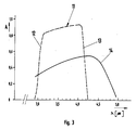
- the graphic in FIG. (3) shows the transmission characteristic of the reflection filter (9) by means of the curve (11) shown in broken lines. It can be seen that the reflection filter (9) has a high slope on both the short-wave side (12) and on the long-wave side (13), which in particular on the long-wave side (13) due to the abrupt drop in permeability in the atmosphere 4.2 ⁇ m wavelength is important. In the range between 4.1 and 4.2 ⁇ m, the permeability of the reflection filter (9) drops from 90% to 10%. Due to the high slope, the spectral range of high transmission in atmospheric window II can be used almost completely, from 3.2 to 4.1 ⁇ m wavelength with a high, between 80% and 90% lying reception amplitude. Due to the arrangement of the reflection filter (9) according to the invention, this characteristic can be produced with high reproducibility and comparatively low costs.
- the solid curve (14) represents the reception amplitude of the detector elements (8). Due to the high reflection of the detector material, this amplitude is significantly lower than that of the reflection filter (9). It can be seen that the curve (14) extends considerably further than the transmission range of the reflection filter (9), which suggests that the mixing ratio of the detector materials is not exactly adhered to. However, this is no longer important because of the precisely adjustable selectivity of the reflection filter (9).
- the reception amplitude can be increased up to that of the reflection filter if the refractive indices of the layers (10) are selected so that the detector elements (8) absorb the IR rays as completely as possible.
Landscapes
- Physics & Mathematics (AREA)
- General Physics & Mathematics (AREA)
- Spectroscopy & Molecular Physics (AREA)
- Engineering & Computer Science (AREA)
- Microelectronics & Electronic Packaging (AREA)
- Condensed Matter Physics & Semiconductors (AREA)
- Electromagnetism (AREA)
- Computer Hardware Design (AREA)
- Power Engineering (AREA)
- Photometry And Measurement Of Optical Pulse Characteristics (AREA)
Abstract
Description
Die Erfindung betrifft eine Vorrichtung zur Erkennung thermischer Kontraste im Temperaturbereich um 300 K und innerhalb zumindest eines atmosphärischen Fensters, mit einem IR-Detektor mit wenigstens einem Detektorelement und einem davor angeordneten Reflexionsfilter, dessen Durchlaßbereich dem Spektralbereich guter Durchlässigkeit im betreffenden atmosphärischen Fenster entspricht.The invention relates to a device for the detection of thermal contrasts in the temperature range around 300 K and within at least one atmospheric window, with an IR detector with at least one detector element and a reflection filter arranged in front thereof, the pass band of which corresponds to the spectral range of good permeability in the relevant atmospheric window.
Eine solche Vorrichtung ist in der CH-PS 5 64 764 bzw. DE-PS 22 33 870 und 22 65 465 beschrieben. Bei dieser Vorrichtung befindet sich im Zentrum einer sphärischen Lochblende und im Brennpunkt eines Objektivs ein Infrarot-Detektor mit einem bzw. einer Reihe von Detektorelement(en). Entsprechende Detektoren sind beispielsweise aus der DE-OS 25 53 378 bekannt.Such a device is described in CH-
Zwischen Detektor und Objektiv ist ein Reflexionsfilter angeordnet, dessen Durchlaßbereich auf einen Teilspektralbereich des atmosphärischen Fensters II - es erstreckt sich etwa zwischen 3 bis 5,3 µm Wellenlänge - begrenzt ist, nämlich auf den Bereich zwischen 3,3 und 4,2 µm Wellenlänge. Hierdurch wurde der Erkenntnis Rechnung getragen, daß die Durchlässigkeit der Atmosphäre bei etwa 4,2 µm, bedingt durch den Gehalt an Kohlendioxid und Wasserdampf, einen starken Einbruch hat, wodurch Störstrahlungen entstehen, die die Kontrastempfindlichkeit stark beeinträchtigen. Durch die Ausgrenzung dieses Bereichs mit Hilfe des Reflexionsfilters konnte somit eine erhebliche Verbesserung der Kontrastempfindlichkeit erzielt werden.A reflection filter is arranged between the detector and the lens, the transmission range of which is limited to a partial spectral range of the atmospheric window II - it extends approximately between 3 to 5.3 µm wavelength - namely to the range between 3.3 and 4.2 µm wavelength. In this way, the knowledge was taken into account that the permeability of the atmosphere at about 4.2 microns, due to the content of carbon dioxide and water vapor, has a sharp drop, which Interference radiation arises that severely impair contrast sensitivity. By delimiting this area with the help of the reflection filter, a significant improvement in contrast sensitivity could be achieved.
Der vorbekannte Reflexionsfilter besteht aus einem IR-transparenten Körper, auf dessen konkave Seite mehrere Schichten eines hierfür geeigneten Materials aufgedampft sind. Materialwahl und Schichtdicke können dabei so gewählt werden, daß der Durchlaßbereich entsprechend den jeweiligen Anforderungen eingestellt und mit hoher Flankensteilheit abgegrenzt werden kann. Es bestand deshalb auch die Möglichkeit, bei dem Gerät der vorbekannten Art die Flankensteilheit entsprechend der Abfallcharakteristik des ausgwählten Teilspektralbereichs auszubilden. Die Herstellung solcher Reflexionsfilter gehört zum allgemeinen Stand der Technik und kann beispielsweise der Literatur "Wolfe, The Infrared Handbook, 1978, S. 7-103 ff" entnommen werden.The known reflection filter consists of an IR-transparent body, on the concave side of which several layers of a suitable material are vapor-deposited. The choice of material and layer thickness can be selected so that the pass band can be set according to the respective requirements and delimited with a high slope. It was therefore also possible to design the slope of the device of the known type in accordance with the decay characteristics of the selected partial spectral range. The production of such reflection filters is part of the general state of the art and can be found, for example, in the literature "Wolfe, The Infrared Handbook, 1978, pp. 7-103 ff".
Soweit die vorbekannte Vorrichtung mehrere Detektorelemente enthält, werden die Störstrahlungen innerhalb des Gehäuses dadurch vermieden, daß die Lochblende derart symmetrisch zum sphärischen Mittelpunkt des Reflexionsfilters justiert wird, daß sich die jeweils symmetrisch zum Mittelpunkt liegenden Detektorelemente im Sperrbereich des Reflexionsfilters gegenseitig abbilden. Diese Maßnahme wie auch die Maßnahme, überhaupt einen Reflexionsfilter zu verwenden, führten dazu, daß Kontrastminderungen infolge Störstrahlungen weitestgehend vermieden werden.Insofar as the known device contains several detector elements, the interference radiation within the housing is avoided in that the pinhole is adjusted so symmetrically to the spherical center of the reflection filter that the detector elements lying symmetrically to the center image each other in the blocking region of the reflection filter. This measure, as well as the measure of using a reflection filter at all, has the effect that contrast reductions due to interference radiation are largely avoided.
Es hat sich jedoch gezeigt, daß die Herstellung des Reflexionsfilters außerordentlich schwierig ist. Bei dem technisch notwendigen kleinen Abstand zwischen Reflexionsfilter und Detektorelement(en) müssen die Filterradien sehr klein sein, und zwar im Bereich weniger Millimeter. Es bereitet große Probleme und gelingt häufig nicht, die Schichten in der hierfür erforderlichen Gleichmäßigkeit aufzudampfen.However, it has been shown that the manufacture of the Reflection filter is extremely difficult. Given the technically necessary small distance between the reflection filter and the detector element (s), the filter radii must be very small, in the range of a few millimeters. It causes great problems and often fails to evaporate the layers with the required uniformity.
Es wurden deshalb Überlegungen und Versuche angestellt, den interessierenden Teilspektralbereich durch Materialwahl und Mischungsverhältnis des für die Herstellung der Detektorelemente verwendeten Detektormaterials einzugrenzen. Dies gestaltete sich jedoch zumindest hinsichtlich des Detektormaterials CdHg:HgTe als fertigungsmäßig ebenso schwierig, da es hierzu der genauen Einstellung des Mischungsverhältnisses und der stöchiometrischen Werte bedarf. Dies ist nur mit außerordentlich hohem Aufwand möglich.Considerations and attempts were therefore made to limit the sub-spectral region of interest by choice of material and mixing ratio of the detector material used for the production of the detector elements. However, at least with regard to the detector material CdHg: HgTe, this turned out to be just as difficult in terms of production, since this requires the exact setting of the mixing ratio and the stoichiometric values. This is only possible with an extremely high outlay.
Bei der Ausführungsform der vorbekannten Vorrichtung mit einer Reihe von Detektorelementen wurde zudem festgestellt, daß durch die spiegelnde Abbildung der Detektorelemente aufeinander im Sperrbereich des Reflexionsfilters ein Übersprechen der Signale auftreten kann. Dies führt zu ertsprechenden Verfälschungen.In the embodiment of the known device with a row of detector elements, it was also found that crosstalk of the signals can occur due to the reflective imaging of the detector elements on one another in the blocking region of the reflection filter. This leads to corresponding falsifications.
Der Erfindung liegt die Aufgabe zugrunde, eine Vorrichtung der eingangs genannten Art so auszubilden, daß der Reflexionsfilter mit jeweils gewünschten Eigenschaften in zuverlässig reproduzierbarer Weise und kostengünstig hergestellt werden kann sowie gleichzeitig ein Übersprechen von Signalen bei Verwendung einer Reihe von Detektorelementen vermieden wird.The invention has for its object to provide a device of the type mentioned in such a way that the reflection filter with the desired properties can be produced in a reliably reproducible and inexpensive manner and at the same time crosstalk of signals is avoided when using a number of detector elements.
Diese Aufgabe wird erfindungsgemäß dadurch gelöst, daß der Reflexionsfilter an dem bzw. den Detektorelement(en) direkt anliegend angebracht ist, vorzugsweise auf diesen bzw. diese aufgedampft ist.According to the invention, this object is achieved in that the reflection filter is attached directly to the detector element (s), preferably vapor-deposited thereon.
Erfindungsgemäß steht also der Reflexionsfilter in direktem Kontakt zu dem IR-Detektor. Da dessen Detektorelemente ebene Flächen darstellen, gestaltet sich das Aufbringen, insbesondere das Bedampfen als vergleichsweise einfach. Der Reflexionsfilter läßt sich mit hoher Genauigkeit auftragen, so daß die jeweils gewünschte Charakteristik mit großer Zuverlässigkeit hergestellt werden kann. Dabei besteht die Möglichkeit, eine Vielzahl von IR-Detektoren in einem Bedampfungsvorgang mit dem Reflexionsfilter zu versehen.According to the invention, the reflection filter is in direct contact with the IR detector. Since its detector elements represent flat surfaces, the application, in particular the vapor deposition, is comparatively simple. The reflection filter can be applied with high accuracy, so that the desired characteristic can be produced with great reliability. It is possible to provide a large number of IR detectors with the reflection filter in one vapor deposition process.
Es besteht somit auch nicht mehr die Notwendigkeit, das Mischungsverhältnis der Detektormaterialien genau einzustellen. Die Selektion kann allein durch den Reflexionsfilter durchgeführt werden.There is therefore no longer any need to precisely adjust the mixing ratio of the detector materials. The selection can be carried out using the reflection filter alone.
Dabei ist von besonderem Vorteil, daß bei einem IR-Detektor mit mehreren Detektorelementen ein Übersprechen der Signale zwischen den Detektorelementen nicht mehr auftreten kann, ohne daß hierfür Beeinträchtigungen durch Störstrahlungen im Sperrbereich in Kauf genommen werden müssen. Ein weiterer Vorteil besteht darin, daß der Reflexionsfilter gleichzeitig eine Schutzschicht darstellt, das Aufbringen einer besonderen Schutzschicht entfallen kann.It is particularly advantageous that, in the case of an IR detector with a plurality of detector elements, crosstalk between the signals between the detector elements can no longer occur without impairment by interference radiation in the blocked region having to be accepted. Another advantage is that the reflection filter also represents a protective layer, and there is no need to apply a special protective layer.
Wie vorstehend dargelegt, bietet es sich an, den Reflexionsfilter direkt auf das bzw. die Detektorelement(e) aufzudampfen. Es besteht jedoch auch die Möglichkeit, den Reflexionsfilter auf einen flachen IR-transparenten Körper aufzubringen, und zwar auch aufzudampfen, und dann diesen Körper mit dem Reflexionsfilter auf das bzw. die Detektorelement(e) direkt aufzulegen. Auch in diesem Fall ist die Herstellung des Reflexionsfilters vergleichsweise einfach.As stated above, it is advisable to vapor-deposit the reflection filter directly onto the detector element (s). However, it also exists the possibility of applying the reflection filter to a flat IR-transparent body, and to do this also by vapor deposition, and then placing this body with the reflection filter directly on the detector element (s). In this case, too, the production of the reflection filter is comparatively simple.
Die Erfindung ist nicht auf die Ausbildung des Reflexionsfilters für den in der CH-PS 5 64 764 erwähnten Teilspektralbereich des atmosphärischen Fensters II beschränkt. Die erfindungsgemäße Ausbildung eignet sich auch für andere Spektralbereiche, und zwar auch für die im Fenster III.The invention is not limited to the formation of the reflection filter for the partial spectral range of the atmospheric window II mentioned in CH-
In der Regel wird der Reflexionsfilter zur Erzielung der jeweils gewünschten Charakteristik aus mehreren Schichten aufgebaut sein, wobei diese Schichten meist λ/4-Schichten sind. Der jeweilige Aufbau kann der Fachliteratur entnommen werden. Bei der erfindungsgemäßen Ausbildung besteht die jedoch die Möglichkeit und wird empfohlen, daß der Brechungsindex bzw. die Brechungsindizes der Schicht(en) so gewählt ist bzw. sind, daß das bzw. die Detektorelement(e) die einfallenden IR-Strahlen möglichst vollständig absorbiert bzw. absorbieren. Auf diese Weise wird ein maximaler Quantenwirkungsgrad erreicht.As a rule, the reflection filter will be constructed from several layers to achieve the desired characteristic, these layers mostly being λ / 4 layers. The respective structure can be found in the specialist literature. In the embodiment according to the invention, however, there is the possibility and it is recommended that the refractive index or the refractive indices of the layer (s) is or are selected such that the detector element (s) absorbs the incident IR rays as completely as possible or absorb. In this way, maximum quantum efficiency is achieved.
In der Zeichnung ist die Erfindung an Hand eines Ausführungsbeispiels näher veranschaulicht. Es zeigen:
- Figur (1) einen Teilquerschnitt durch einen IR-Detektor;
- Figur (2) eine vergrößerte Darstellung der Detektorelemente des IR-Detektors gemäß Figur (1) und
- Figur (3) eine Grafik zur Darstellung der Empfangsamplitude über die Wellenlänge bezüglich des Reflexionsfilters und der Detektorelemente des IR-Detektors gemäß den Figuren (1) und (2).
- Figure (1) shows a partial cross section through an IR detector;
- Figure (2) is an enlarged view of the detector elements of the IR detector according to Figure (1) and
- Figure (3) is a graph showing the reception amplitude over the wavelength with respect to the reflection filter and the detector elements of the IR detector according to Figures (1) and (2).
Der in Figur (1) dargestellte IR-Detektor (1) weist ein topfförmiges Gehäuse (2) auf, an dessen Boden ein Gewindezapfen (3) angesetzt ist, der zur Befestigung an einer entsprechenden Vorrichtung bestimmt ist. Das Gehäuse (2) wird obenseitig mit einer planen Saphirscheibe (4) abgeschlossen. In diesem Bereich ist zusätzlich auch noch ein Flansch (5) angeformt. Vor der Saphirscheibe (4) ist noch eine Optik angeordnet, die hier jedoch weggelassen ist.The IR detector (1) shown in Figure (1) has a cup-shaped housing (2), on the bottom of which a threaded pin (3) is attached, which is intended for attachment to a corresponding device. The housing (2) is closed on the top with a flat sapphire disc (4). A flange (5) is also formed in this area. An optic is arranged in front of the sapphire disc (4), but is omitted here.
In dem Gehäuse (2) befindet sich ein Kühlkörper (6), dessen nähere Ausgestaltung dem Stand der Technik entnommen werden kann und nicht Gegenstand der vorliegenden Erfindung ist. Es wird deshalb auf eine Beschreibung im Detail verzichtet. Auf einer planen Grundplatte (7) ist eine Reihe von Detektorelementen - beispielhaft mit (8) bezeichnet - aufgebracht, die ebenfalls in an sich bekannter Weise gestaltet sind. Im vorliegenden Beispiel bestehen sie aus einer Kristallmischung CdHg:HgTe, da diese Detektorelemente (8) - wie Figur (3) zeigen wird - für den Empfang im atmosphärischen Fenster II bestimmt sind.In the housing (2) there is a heat sink (6), the detailed design of which can be found in the prior art and is not the subject of the present invention. A detailed description is therefore omitted. On a flat base plate (7), a number of detector elements - designated by way of example (8) - are applied, which are also designed in a manner known per se. In the present example they consist of a crystal mixture CdHg: HgTe, since these detector elements (8) - as Figure (3) will show - are intended for reception in the atmospheric window II.
Auf die Detektorelemente (8) ist ein Reflexionsfilter (9) aufgedampft, was in Figur (1) nicht näher dargestellt ist, sich aber aus der vergrößerten Darstellung in Figur (2) ersehen läßt. Dabei sind die einzelnen Schichten - beispielhaft mit (10) bezeichnet -, was ihre Dicke angeht, aus zeichnerischen Gründen nochmals stark vergrößert. Außerdem sind die Schichten (10) - ebenfalls aus zeichnerischen Gründen - gerade durchgezogen dargestellt. Tatsächlich liegen sie in den Zwischenräumen zwischen den Detektorelementen(8) an der Grundplatte (7) an.A reflection filter (9) is placed on the detector elements (8) evaporated, which is not shown in Figure (1), but can be seen from the enlarged view in Figure (2). The individual layers - designated by way of example with (10) - have again been greatly enlarged in terms of their thickness for drawing reasons. In addition, the layers (10) - also for drawing reasons - are shown in solid lines. In fact, they lie in the spaces between the detector elements (8) on the base plate (7).
Es sind hier insgesamt nur vier Schichten eingezeichnet. Es können jedoch zur Erreichung hoher Flankensteilheit auch zehn und mehr Schichten vorgesehen werden, wobei die Dicke der Schichten jeweils im λ/4-Bereich liegen. Durch Verwendung entsprechender Materialien und damit Brechungsindizes kann erreicht werden, daß die Detektorelemente (8) die einfallenden IR-Strahlen praktisch vollständig absorbieren.Only four layers are shown here. However, ten or more layers can also be provided to achieve high edge steepness, the thickness of the layers each being in the λ / 4 range. By using appropriate materials and thus refractive indices, it can be achieved that the detector elements (8) practically completely absorb the incident IR rays.
Die Grafik in Figur (3) zeigt durch die in gestrichelter Darstellung gehaltene Kurve (11) die Durchlaßcharakteristik des Reflexionsfilters (9). Es ist zu sehen, daß der Reflexionsfilter (9) sowohl auf der kurzwelligen Seite (12) als auch auf der langwelligen Seite (13) eine hohe Flankensteilheit hat, was insbesondere auf der langwelligen Seite (13) wegen des abrupten Durchlässigkeitsabfalls in der Atmosphäre bei 4,2 µm Wellenlänge wichtig ist. Im Bereich zwischen 4,1 und 4,2 µm fällt die Durchlässigkeit des Reflexionsfilters (9) von 90% auf 10% ab. Aufgrund der hohen Flankensteilheit kann ansonsten der Spektralbereich hoher Durchlässigkeit im atmosphärischen Fenster II fast vollständig ausgenutzt werden, und zwar von 3,2 bis 4,1 µm Wellenlänge mit einer hohen, zwischen 80% und 90% liegenden Empfangsamplitude. Aufgrund der erfindungsgemäßen Anordnung des Reflexionsfilters (9) läßt sich diese Charakteristik mit hoher Reproduzierbarkeit und vergleichsweise geringen Kosten herstellen.The graphic in FIG. (3) shows the transmission characteristic of the reflection filter (9) by means of the curve (11) shown in broken lines. It can be seen that the reflection filter (9) has a high slope on both the short-wave side (12) and on the long-wave side (13), which in particular on the long-wave side (13) due to the abrupt drop in permeability in the atmosphere 4.2 µm wavelength is important. In the range between 4.1 and 4.2 µm, the permeability of the reflection filter (9) drops from 90% to 10%. Due to the high slope, the spectral range of high transmission in atmospheric window II can be used almost completely, from 3.2 to 4.1 µm wavelength with a high, between 80% and 90% lying reception amplitude. Due to the arrangement of the reflection filter (9) according to the invention, this characteristic can be produced with high reproducibility and comparatively low costs.
Die durchgezogene Kurve (14) stellt die Empfangsamplitude der Detektorelemente (8) dar. Aufgrund der hohen Reflexion des Detektormaterials ist diese Amplitude wesentlich geringer als die des Reflexionsfilters (9). Es ist zu erkennen, daß die Kurve (14) sich erheblich weiter erstreckt als der Durchlässigkeitsbereich des Reflexionsfilters (9) geht, was auf nicht genaue Einhaltung des Mischungsverhältnisses der Detektormaterialien schließen läßt. Darauf kommt es jedoch wegen der genau einstellbaren Selektivität des Reflexionsfilters (9) nicht mehr an.The solid curve (14) represents the reception amplitude of the detector elements (8). Due to the high reflection of the detector material, this amplitude is significantly lower than that of the reflection filter (9). It can be seen that the curve (14) extends considerably further than the transmission range of the reflection filter (9), which suggests that the mixing ratio of the detector materials is not exactly adhered to. However, this is no longer important because of the precisely adjustable selectivity of the reflection filter (9).
Im übrigen kann die Empfangsamplitude bis in den Bereich derjenigen des Reflexionsfilters gesteigert werden, wenn die Brechungsindizes der Schichten (10) so gewählt werden, daß die Detektorelemente (8) die IR-Strahlen möglichst vollständig absorbieren.In addition, the reception amplitude can be increased up to that of the reflection filter if the refractive indices of the layers (10) are selected so that the detector elements (8) absorb the IR rays as completely as possible.
Claims (4)
dadurch gekennzeichnet, daß der Reflexionsfilter (9) an dem bzw. den Detektorelement(en) (8) direkt anliegend angebracht ist.1. Device for detecting thermal contrasts in the temperature range around 300 K and within at least one atmospheric window, with an IR detector (1) with at least one detector element (8) and a reflection filter (9) arranged in front thereof, the pass band of the spectral range of good permeability in corresponds to the atmospheric window concerned,
characterized in that the reflection filter (9) is attached directly to the detector element (s) (8).
dadurch gekennzeichnet, daß der Reflexionsfilter (9) auf den bzw. die Detektorelement(e) (8) aufgedampft ist.2. Device according to claim 1,
characterized in that the reflection filter (9) is evaporated onto the detector element (s) (8).
dadurch gekennzeichnet, daß der Reflexionsfilter (9) aus mehreren Schichten (10) aufgebaut ist.3. Device according to claim 1 or 2,
characterized in that the reflection filter (9) is constructed from a plurality of layers (10).
dadurch gekennzeichnet, daß der Brechungsindex bzw. die Brechungsindizes der Schicht(en) (10) so gewählt ist bzw. sind, daß das bzw. die Detektorelement(e) (8) die einfallenden IR-Strahlen möglichst vollständig absorbiert bzw. absorbieren.4. The device according to claim 3,
characterized in that the refractive index or indices of the layer (s) (10) is or are selected such that the detector element (s) (8) absorb the incident IR rays as completely as possible.
Priority Applications (1)
| Application Number | Priority Date | Filing Date | Title |
|---|---|---|---|
| EP86109562A EP0253002A1 (en) | 1986-07-12 | 1986-07-12 | Device for the detection of thermal contrasts |
Applications Claiming Priority (1)
| Application Number | Priority Date | Filing Date | Title |
|---|---|---|---|
| EP86109562A EP0253002A1 (en) | 1986-07-12 | 1986-07-12 | Device for the detection of thermal contrasts |
Publications (1)
| Publication Number | Publication Date |
|---|---|
| EP0253002A1 true EP0253002A1 (en) | 1988-01-20 |
Family
ID=8195264
Family Applications (1)
| Application Number | Title | Priority Date | Filing Date |
|---|---|---|---|
| EP86109562A Withdrawn EP0253002A1 (en) | 1986-07-12 | 1986-07-12 | Device for the detection of thermal contrasts |
Country Status (1)
| Country | Link |
|---|---|
| EP (1) | EP0253002A1 (en) |
Cited By (4)
| Publication number | Priority date | Publication date | Assignee | Title |
|---|---|---|---|---|
| EP0429089A2 (en) * | 1989-11-24 | 1991-05-29 | SELENIA INDUSTRIE ELETTRONICHE ASSOCIATE S.p.A. | Horizon sensor for satellites |
| WO1994009517A1 (en) * | 1992-10-13 | 1994-04-28 | Fraunhofer-Gesellschaft zur Förderung der angewandten Forschung e.V. | Ir-absorption device |
| US5589689A (en) * | 1994-07-07 | 1996-12-31 | Vaisala Oy | Infrared detector with Fabry-Perot interferometer |
| DE102008007674B3 (en) * | 2008-01-28 | 2009-05-14 | Technische Universität Dresden | Method for producing absorption layers on thermal radiation sensors |
Citations (4)
| Publication number | Priority date | Publication date | Assignee | Title |
|---|---|---|---|---|
| US3875408A (en) * | 1972-07-10 | 1975-04-01 | Gunter Pusch | Method and device for ascertaining thermal constrasts |
| US4158133A (en) * | 1976-08-20 | 1979-06-12 | Siemens Aktiengesellschaft | Filters for photo-detectors |
| JPS57104275A (en) * | 1980-12-19 | 1982-06-29 | Nec Corp | Light receiving element |
| JPS59230120A (en) * | 1983-06-10 | 1984-12-24 | Agency Of Ind Science & Technol | Optical sensor |
-
1986
- 1986-07-12 EP EP86109562A patent/EP0253002A1/en not_active Withdrawn
Patent Citations (4)
| Publication number | Priority date | Publication date | Assignee | Title |
|---|---|---|---|---|
| US3875408A (en) * | 1972-07-10 | 1975-04-01 | Gunter Pusch | Method and device for ascertaining thermal constrasts |
| US4158133A (en) * | 1976-08-20 | 1979-06-12 | Siemens Aktiengesellschaft | Filters for photo-detectors |
| JPS57104275A (en) * | 1980-12-19 | 1982-06-29 | Nec Corp | Light receiving element |
| JPS59230120A (en) * | 1983-06-10 | 1984-12-24 | Agency Of Ind Science & Technol | Optical sensor |
Non-Patent Citations (2)
| Title |
|---|
| PATENTS ABSTRACTS OF JAPAN, Band 6, Nr. 194 (E-134)[1072], 2. Oktober 1982; & JP-A-57 104 275 (NIPPON DENKI K.K.) 29-06-1982 * |
| PATENTS ABSTRACTS OF JAPAN, Band 9, Nr. 109 (P-355)[1832], 14. Mai 1985; & JP-A-59 230 120 (KOGYO GIJUTSUIN (JAPAN)) 24-12-1984 * |
Cited By (6)
| Publication number | Priority date | Publication date | Assignee | Title |
|---|---|---|---|---|
| EP0429089A2 (en) * | 1989-11-24 | 1991-05-29 | SELENIA INDUSTRIE ELETTRONICHE ASSOCIATE S.p.A. | Horizon sensor for satellites |
| EP0429089A3 (en) * | 1989-11-24 | 1992-10-28 | Selenia Industrie Elettroniche Associate S.P.A. | Horizon sensor for satellites |
| WO1994009517A1 (en) * | 1992-10-13 | 1994-04-28 | Fraunhofer-Gesellschaft zur Förderung der angewandten Forschung e.V. | Ir-absorption device |
| US5578858A (en) * | 1992-10-13 | 1996-11-26 | Fraunhofer-Gesellschaft Zur Foerderung Der Angewandten Forschung E.V. | Infrared radiation absorption device |
| US5589689A (en) * | 1994-07-07 | 1996-12-31 | Vaisala Oy | Infrared detector with Fabry-Perot interferometer |
| DE102008007674B3 (en) * | 2008-01-28 | 2009-05-14 | Technische Universität Dresden | Method for producing absorption layers on thermal radiation sensors |
Similar Documents
| Publication | Publication Date | Title |
|---|---|---|
| DE3881385T2 (en) | WEDGE FILTER SPECTROMETER. | |
| DE1622498B1 (en) | FILTER ARRANGEMENT WITH A PASS-THROUGH BAND FROM ULTRAVIOLET TO ABOUT INFRARED | |
| DE10304312A1 (en) | Compact spectrometer | |
| DE102014014983A1 (en) | Optical filter element for spectroscopic devices for converting spectral information into location information | |
| DE60035048T2 (en) | METHOD OF MANUFACTURING OPTICAL ELEMENTS | |
| DE60204249T2 (en) | Optical detector | |
| DE69422874T2 (en) | Improvements in or with respect to detector arrays | |
| DE3026370A1 (en) | MIRROR | |
| DE69901054T2 (en) | EYEWEAR LENS AND METHOD FOR THEIR PRODUCTION | |
| EP0355672B1 (en) | Filter for protection against the sun | |
| EP0253002A1 (en) | Device for the detection of thermal contrasts | |
| DE2912210A1 (en) | RADIATION DETECTOR WITH A TRAPEZOIDAL SCINTILLATOR | |
| AT410257B (en) | DEVICE FOR CHECKING AND CHECKING A SINGLE GLASS PANEL OR INSULATING GLASS ELEMENT | |
| DE19514044A1 (en) | Radiation dosimeter for detection and dosimetry of esp. UV radiation | |
| CH622353A5 (en) | ||
| DE3408792C2 (en) | Device for pyrometric temperature measurement | |
| DE4242440C1 (en) | Semiconductor foil beam splitter for infrared spectrometer - consists of far-infrared-transparent non-doped material, e.g thin silicon wafer or diamond foil | |
| DE69506180T2 (en) | Optoelectronic camera for a spectral imaging device or spectrophotometer, light-sensitive unit and protective window for such a camera and method for carrying out such an arrangement | |
| DE2238097A1 (en) | OPTICAL ELEMENT | |
| DE4201024A1 (en) | PORTABLE SPECTRAL PHOTOMETER FOR SITU EXAMINATION OF THE ABSORPTION SPECTRUM OF A SUBSTANCE | |
| DE3413175C2 (en) | ||
| DE2749229C2 (en) | Non-dispersive infrared gas analyzer | |
| DE3885363T2 (en) | Package structure for semiconductor device. | |
| DE718040C (en) | Translucent mirror for optical purposes | |
| DE102017201139A1 (en) | Device for limiting an angle of incidence of light, method of making the same, and microspectrometer |
Legal Events
| Date | Code | Title | Description |
|---|---|---|---|
| PUAI | Public reference made under article 153(3) epc to a published international application that has entered the european phase |
Free format text: ORIGINAL CODE: 0009012 |
|
| AK | Designated contracting states |
Kind code of ref document: A1 Designated state(s): AT BE CH DE FR GB IT LI LU NL SE |
|
| STAA | Information on the status of an ep patent application or granted ep patent |
Free format text: STATUS: THE APPLICATION IS DEEMED TO BE WITHDRAWN |
|
| 18D | Application deemed to be withdrawn |
Effective date: 19880721 |