EP0252927B1 - Bestimmung der fliesseigenschaften von teilchenmaterial - Google Patents
Bestimmung der fliesseigenschaften von teilchenmaterial Download PDFInfo
- Publication number
- EP0252927B1 EP0252927B1 EP86906700A EP86906700A EP0252927B1 EP 0252927 B1 EP0252927 B1 EP 0252927B1 EP 86906700 A EP86906700 A EP 86906700A EP 86906700 A EP86906700 A EP 86906700A EP 0252927 B1 EP0252927 B1 EP 0252927B1
- Authority
- EP
- European Patent Office
- Prior art keywords
- particulate material
- test cell
- flow
- load
- consolidation
- Prior art date
- Legal status (The legal status is an assumption and is not a legal conclusion. Google has not performed a legal analysis and makes no representation as to the accuracy of the status listed.)
- Expired
Links
- 239000011236 particulate material Substances 0.000 title claims abstract description 74
- 238000012360 testing method Methods 0.000 claims abstract description 139
- 238000007596 consolidation process Methods 0.000 claims abstract description 71
- 230000005484 gravity Effects 0.000 claims abstract description 27
- 238000011021 bench scale process Methods 0.000 claims abstract description 5
- 238000000034 method Methods 0.000 claims description 35
- 230000000284 resting effect Effects 0.000 claims description 4
- 239000000463 material Substances 0.000 abstract description 63
- 238000010998 test method Methods 0.000 abstract description 22
- 239000004033 plastic Substances 0.000 abstract description 4
- 239000007787 solid Substances 0.000 description 10
- 239000002245 particle Substances 0.000 description 6
- 125000006850 spacer group Chemical group 0.000 description 6
- 239000000843 powder Substances 0.000 description 4
- 230000000694 effects Effects 0.000 description 3
- 239000013618 particulate matter Substances 0.000 description 3
- XEEYBQQBJWHFJM-UHFFFAOYSA-N Iron Chemical compound [Fe] XEEYBQQBJWHFJM-UHFFFAOYSA-N 0.000 description 2
- 229910000831 Steel Inorganic materials 0.000 description 2
- 230000001133 acceleration Effects 0.000 description 2
- 238000013459 approach Methods 0.000 description 2
- 238000005056 compaction Methods 0.000 description 2
- 230000003247 decreasing effect Effects 0.000 description 2
- 238000013461 design Methods 0.000 description 2
- 238000002474 experimental method Methods 0.000 description 2
- 239000008187 granular material Substances 0.000 description 2
- 239000012528 membrane Substances 0.000 description 2
- 239000002184 metal Substances 0.000 description 2
- 229910052751 metal Inorganic materials 0.000 description 2
- 230000035939 shock Effects 0.000 description 2
- 239000010959 steel Substances 0.000 description 2
- 230000002745 absorbent Effects 0.000 description 1
- 239000002250 absorbent Substances 0.000 description 1
- 239000003245 coal Substances 0.000 description 1
- 238000005516 engineering process Methods 0.000 description 1
- 235000013312 flour Nutrition 0.000 description 1
- -1 gravel Substances 0.000 description 1
- 230000002452 interceptive effect Effects 0.000 description 1
- 229910052742 iron Inorganic materials 0.000 description 1
- 238000005259 measurement Methods 0.000 description 1
- 238000012986 modification Methods 0.000 description 1
- 230000004048 modification Effects 0.000 description 1
- 238000012856 packing Methods 0.000 description 1
- 239000004576 sand Substances 0.000 description 1
- 238000004513 sizing Methods 0.000 description 1
- 239000000126 substance Substances 0.000 description 1
- XLYOFNOQVPJJNP-UHFFFAOYSA-N water Substances O XLYOFNOQVPJJNP-UHFFFAOYSA-N 0.000 description 1
Images

Classifications
-
- G—PHYSICS
- G01—MEASURING; TESTING
- G01N—INVESTIGATING OR ANALYSING MATERIALS BY DETERMINING THEIR CHEMICAL OR PHYSICAL PROPERTIES
- G01N11/00—Investigating flow properties of materials, e.g. viscosity, plasticity; Analysing materials by determining flow properties
- G01N11/02—Investigating flow properties of materials, e.g. viscosity, plasticity; Analysing materials by determining flow properties by measuring flow of the material
-
- G—PHYSICS
- G01—MEASURING; TESTING
- G01N—INVESTIGATING OR ANALYSING MATERIALS BY DETERMINING THEIR CHEMICAL OR PHYSICAL PROPERTIES
- G01N33/00—Investigating or analysing materials by specific methods not covered by groups G01N1/00 - G01N31/00
- G01N33/0091—Powders
-
- G—PHYSICS
- G01—MEASURING; TESTING
- G01N—INVESTIGATING OR ANALYSING MATERIALS BY DETERMINING THEIR CHEMICAL OR PHYSICAL PROPERTIES
- G01N2203/00—Investigating strength properties of solid materials by application of mechanical stress
- G01N2203/0058—Kind of property studied
- G01N2203/0076—Hardness, compressibility or resistance to crushing
- G01N2203/0085—Compressibility
Definitions
- the present invention is in the field of bulk particulate solids and more specifically relates to an apparatus and testing method for determining on the basis of bench scale testing whether particulate matter will flow under the action of gravity through an outlet in the bottom of a container.
- Bulk solids in a divided state such as flour, sugar, ores, dry chemicals and coal are generally handled in silos or containers that require gravity flow for discharge.
- silos or containers that require gravity flow for discharge.
- One of the problems of designing such containers is sizing of the outlet so that the solids do not form an obstruction by arching across the outlet.
- the size of outlet required to prevent arching is a function of the unconfined yield strength of the material, the density of the material, and the shape of the outlet.
- US-A-2 633 027 discloses a method of testing flow characteristics of granular materials by confining a predetermined amount of a granular material within a restricted space on a support, applying a predetermined pressure on the material in a direction to pack it in the restricted space, removing the pressure from the material, removing the support on which the material is positioned to determine whether any portion of the material is bridged across the restricted space, and repeating the above-outlined steps with incremental increases in the pressure applied to the material until a portion of the material is packed sufficiently to cause it to bridge across the space, whereby the packing point of the material is determined.
- a further objective is to provide an apparatus and test method that is applicable to conical containers as well as to containers of rectangular horizontal cross section.
- the portion of the test chamber in which the material is tested includes no cylindrical walls that contact the material, and in this way the uncertainty associated with the frictional effects of cylindrical walls is eliminated.
- the side walls of the test chamber conform to the surface of a cone, and the larger end of the conical section is closed by a plug that includes an inwardly facing coaxial concave surface.
- This unique shape of the test chamber affords minimum interference with the plastic stress field present in the material.
- the conical walls provide an increasing cross sectional area in the direction of motion so as to minimize the frictional effects of the walls.
- the same conical walls provide a decreasing cross sectional area in the direction of motion to insure an arching condition similar to that occurring in a hopper during failure conditions.
- the material to be tested is consolidated in the test cell with the concave plug at the bottom of the test cell, and then the entire test cell including the concave plug is turned upside down for the failure loading portion of the test.
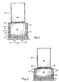
- Figure 1 a preferred embodiment of the apparatus that is used for performing the tests described below.
- the apparatus includes a consolidation base 20 which rests on the floor or on a bench.
- the conical plug 10 rests on the base 20 with its conical surface 18 facing the inside of the test cell 12.
- the shape of the space enclosed by the test cell 12 and by the conical plug 10 is an important aspect of the present invention, as will be described below.
- the test cell 12 is a unitary sleeve-like part having a conical inside surface 14 shaped to conform to a truncated cone joined at its larger diameter to a cylindrical inside surface 16.
- the conical inside surface 14 is inclined to the vertical by approximately six degrees, so that it could also be said that the cone to which the surface 14 conforms has a vertex angle of twelve degrees, in the preferred embodiment. If the semi-angle is less than four degrees, the convergence will be insufficient to form an arch during the failure step of the test procedure. On the other hand, the angle must not be so great that it becomes incompatable with the mass flow stress field in the test cell during the failure step of the test procedure.
- the conical plug 10 is slightly smaller in diameter than the cylindrical inside surface 16 so that the plug 10 can, at a later stage of the test, move freely in the axial direction with respect to the test cell 12.
- the height of the conical plug 10 in the axial direction is slightly less than the height of the cylindrical inside surface 16 to accommodate some movement by the plug in the axial direction.
- the apparatus further includes a mold ring 24 that rests upon the test cell 12 and that has a diameter approximately equal to the diameter of the opening at the top 34 of the test cell.
- test cell 12 and the mold ring 24 are filled with the material 32 under test, and the material 32 is then consolidated to a specific degree.
- the consolidation is accomplished by placing the flat disk 26 on top of the material 32 under test.
- the diameter of the flat disk is slightly less than the inside diameter of the mold ring 24 to permit the disk 26 to move downwardly into the mold ring 24 without contacting the mold ring.
- a consolidation load container 28 is then rested upon the disk 26 and is slowly filled with a particulate ballast material 30 to a specific pre-calculated depth H.
- All of the parts of the apparatus are made of steel in the preferred embodiment, although in other embodiments any strong durable non-absorbent material may be used.
- the material in the full-size hopper typically includes a degree of moisture
- the material 32 under test also contains moisture, and it is important to prevent the loss of this moisture, since it affects the accuracy of the results. For this reason, a metal or rubber keeper ring 22 tightly encircles the crack between the test cell 12 and the base 20.
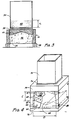
- the length of time during which the consolidation load is applied should approximate the dead time of the material in the proposed hopper, and if this amounts to an appreciable amount of time, it may be essential to take the additional step against moisture loss shown in Figure 2.
- a moisture seal 40 is inserted between the material 32 under test and the disk 26.
- the moisture seal 40 consists of a thin sheet of pliable plastic, which is held in place by the keeper 42.
- the keeper 42 in a preferred embodiment consists of a band of metal or rubber.
- Figure 3 shows the apparatus at a later stage of the test method. After the material being tested has consolidated for the desired length of time, the moisture seals are removed and the test cell 12 is turned upside down and placed on the failure base 48.
- the failure base 48 is merely a support which does not interfere with the material in the test cell or prevent the material 32 from falling out of the test cell. Note that in Figure 3, the test cell 12 is upside down relative to its position in Figures 1 and 2, and that the conical plug 10 remains in place in the test cell.
- the failure disk 54 On top of the conical plug is placed the failure disk 54 which, in a preferred embodiment, is a disk of steel which serves to evenly distribute the applied failure load.
- the failure load container 50 which is not necessarily the same as the consolidation load container 28, is placed on top of the failure disk 54 and is gradually filled with a ballast material, such as sand, gravel, or water. At some point as additional failure load material 52 is added, the pressure loading on the material 32 becomes too great to resist, and the material 32 collapses and falls out of the test cell 12. The height H1 of the failure load material 52 at the instant of failure is carefully noted and, as will be seen below, is used in calculating the test results.
- a ballast material such as sand, gravel, or water.
- the conical shape of the test cell is an important aspect of the invention.
- this shape provides an increase in area in the direction of flow, insuring a minimum of frictional reaction from the walls of the test cell during the consolidation phase, thereby permitting a nearly uniform and known compaction of the material tested.
- the conical shape of the test cell provides a decreasing cross sectional area in the direction of flow so as to simulate the condition occurring in a full-scale hopper.
- the apparatus shown in Figures 1-3 is used for determining whether a particulate material in a large container will flow by the action of gravity alone through a circular outlet in the bottom of the container. If, instead of being circular, the outlet is rectangular, the apparatus shown in Figure 4 may be used. That apparatus is in every sense the rectangular analog of the apparatus shown in Figures 1-3.
- a trough-shaped plug 60 having the inclined plane faces 68 extends into the test cell 62.
- the test cell 62 is rectangular in horizontal cross-section.
- the right and left walls as shown in Figure 4 each include a vertical portion 66 and an inclined portion 64.
- the front and rear walls are vertical only, and are provided with removable panels 84 that are held in place by removable pins of which the pin 72 is typical.
- Figure 4 is comparable to Figure 1 in that it shows the apparatus in the initial stage of the testing.
- a rectangular mold frame 74 rests on top of the test cell 62, and is comparable to the mold ring 24 of Figure 1.
- a consolidation plate 76 is interposed between the consolidation load container 78 and the material 82 under test. The entire apparatus rests on a consolidation base 70.
- test procedure is substantially the same for the embodiments of Figures 1 and 4.
- the apparatus shown and described when used in accordance with the test procedure given below, can be used to predict whether a circular or rectangular outlet in the bottom of a container partially filled with a particulate material will discharge under the action of gravity alone or whether, instead, arching of the material above the outlet will develop to prevent the desired flow. It will be seen below, that in addition to determining whether or not flow will occur, the method can be used to determine the size of outlet required to prevent arching and, with some minor modifications, can be used to measure the unconfined yield strength of the material under test.
- the test cell 12 with the conical plug 10 are resting on the base 20.
- the mold ring 2d is assumed to be resting on the test cell 12.
- the test cell is filled with the material under test to the top of the mold ring.
- the disk 26 is placed on top of the material 32, the consolidation load container 28 is placed on top of the disk 26, and the consolidation load 30 is poured into the container 28. This causes the material 32 to consolidate, and if the material 32 has consolidated to a level below the top 34 of the test cell, it is necessary to remove the consolidation container, to refill the mold ring 24, and to apply the consolidation load 30 again to the material 32 until the consolidation level does not sink below the top 34 of the test cell.
- the mold ring 24 is removed and the material 32 is scraped level with the top 34 of the test cell. Thereafter, the disk 26 and the consolidation load container 28 are replaced as shown in Figure 2, and the consolidation load 30 is applied and allowed to sit for a time equal to the time at rest of the material within the container being simulated. If this time at rest is in excess of a few minutes, it is necessary to cover the test cell with a moisture impermeable seal such as the moisture seal 40 shown in Figure 2.
- H F 1 + m ⁇ 1 ⁇ 2 A1 A2 B - W c ⁇ 2A2
- the overpressure factor F accounts for the additional pressure caused by forces other than gravity that may be operative on the container being simulated.
- Examples include vibration, the impact of a falling stream of particles entering the container, and the presence of gas pressure gradients within the material in the container such as might be caused by a flow of gas through the solids from top to bottom.
- a downwardly acting gas pressure gradient of magnitude dp/dx can be accounted for by setting where ⁇ is the bulk density of the material in the container and dp/dx is the pressure gradient in the upward direction.
- the consolidation load container 28, the disk 26, and the moisture seal 40 are removed and the test cell 12 along with the base 20, and including the conical plug 10 are turned upside down and placed on the failure base 48 in the position shown in Figure 3. Assuming the material 32 has a measurable cohesion, it should not fall out of the test cell in response to the shocks normally encountered in handling the apparatus, although clearly, shocks are to be avoided. Thereafter, the base 20 is removed and the failure disk 54 and the failure load container 50 are stacked on top of the conical plug 10 as shown in Figure 3. It is important that the disk 54 and the container 50 do not touch the test cell during the remaining phases of the test.
- the failure load 52 is very gradually poured into the failure load container 50 until failure of the material in the load cell occurs. Typically, such failures are rather abrupt and most of the material within the test cell will fall out upon failure. Very little actual movement of the conical plug 10 occurs before failure, and this limited movement is permitted by the clearance between the conical plug 10 and the inside of the test cell.
- the height H1 of the material 52 within the failure load container 50 at the time of failure is determined by leveling the material in the failure load container 50 and measuring the height H1 shown in Figure 3.
- test procedure for the rectangular opening using the apparatus of Figure 4 is identical to the procedure just described with the exception that the value of m is different from that used for the circular opening, and the symbol B is defined to be the width of the rectangular outlet which has vertical inlet walls or is infinitely long, and D is the width of the rectangular test cell. It is seen that these differences affect only the magnitude of the consolidation load and the calculated value of H1, but do not otherwise affect the steps of the test procedure.
- the unconfined yield strength of the material is to be determined.
- the pressure at the time of failure can be determined in other ways than using the failure load container 50 and the failure load 52 of Figure 3.
- FIG. 5 A second preferred embodiment is shown in Figure 5 and 6, during the consolidation phase and at the beginning of the failure phase of the test procedure respectively.
- the other parts of the apparatus are supported above the floor 88 or bench top by a bottom spacer ring 100.
- the test cell in this embodiment includes a ring 92 that has a conical inner surface 94.
- the ring 92 is supported on the plug support ring 96, which in turn rests on the bottom spacer ring 100.
- the height of the ring 92 is C, and D represents the diameter of the larger end of the conical surface 94.
- the plug 90 which in one version of this embodiment includes the cylindrical spacer 102, spans the larger diameter end of the conical surface 94 and rests on a beveled portion of the plug support ring 96. In addition to supporting the plug 90, the beveled portion of the ring 96 centers the plug 90.
- the concave conical surface 98 of the plug 90 faces the interior of the test chamber. In accordance with the present invention, the inwardly-facing surface of the plug 90 must be concave, but it does not necessarily have to be conical.
- a mold ring 104 rests on the ring 92.
- the inside surface of the mold ring is cylindrical and its diameter is the same as the diameter of the smaller end of the conical surface 94, so that the mold ring 104 forms an upward extension of the ring 92.
- the consolidation pressure is applied, in one version of this embodiment, by applying a weight to the consolidation disk 106 that rests on the particulate material 112.
- the disk 106 has a diameter slightly smaller than the inside diameter of the mold ring 104, to permit the disk 106 to move freely in the axial direction as the material 112 compacts.
- a spacer 114 supports a consolidation load container 108 a short distance above the disk 106.
- the consolidation load may be increased by adding consolidation ballast 110 to the consolidation load container 108.
- the direction of movement of the particles is downward toward the plug 90.
- the downwardly-diverging shape of the conical surface 94 prevents friction between that surface and the particulate material from interfering with the movement of the particles.
- the consolidation load should be applied to the particulate material in the test cell for an interval of time approximately equal to the time at rest of the particulate material in the full-size hopper. If the material is moist and if the time is long, a moisture retaining membrane similar to the membrane 40 of Figure 2 may be employed to prevent loss of moisture.
- the load is removed.
- the mold ring 104 is removed and the consolidated material above the ring 92 is removed.
- the rings 92 and 96 along with the plug 90 are inverted, care being taken to prevent relative movement of the rings 92 and 96, and to avoid bumping the exposed portions of the plug 90.
- the ring 92 is gently lowered onto the bottom spacer ring 100, so that the apparatus then has the configuration shown in Figure 6.
- the failure load container 116 which may be identical to the consolidation load container 108, is then placed on the spacer 102.
- the load on the particulate material is gradually increased by adding ballast to the failure load container 116, until failure occurs. The load at which failure occurs is then noted.
- the outside diameter of the plug 90 is slightly less than the diameter of the larger-diameter end of the surface 94. This is shown somewhat exaggerated in Figures 5 and 6 for clarity. Likewise, the wall thickness of the plug 90 is exaggerated in the drawings.
- the downwardly converging surface 94 simulates the downwardly converging walls of the full-size hopper.
- any of several flow-related properties of the particulate material may be ascertained by use of the apparatus of this second preferred embodiment.
- the equations for the apparatus of this second preferred embodiment are identical to those used in the first preferred embodiment described above.
- test cell for scale-model testing to determine whether or not flow will occur under the action or gravity from a circular or a rectangular outlet in the bottom of a container that is partly filled with particulate matter.
- the shape of the space within the test cell is of particular significance.
- the test chamber walls conform to the surface of a cone, and the end of the test chamber is plugged by a movable plug having a concave inwardly-facing surface. Accordingly, the material under test never contacts a cylindrical wall and this reduces test error caused by the unknown frictional forces that come into play when the material contacts a cylindrical wall.
- shape of the test cell is designed to not interfere with the plastic stress field that develops in the sample during testing. Accordingly, the novel shape of the test cell is highly advantageous and results in greater accuracy.
- the apparatus for use in ascertaining the flow properties of a particulate material can be said to comprise a hollow test cell that includes a frustrated wedge section defined by the inwardly-facing surface 14 conforming to a section of a wedge, said frustrated wedge section having a smaller end and a larger end; and, the plug 60 which is located adjacent to and spanning the larger end of the frustrated wedge section, but is slightly narrower than it, so as to be freely movable a limited distance into the space within the frustrated wedge section.
- the vertex semi-angle of the frustrated wedge section is in the range between a minimum of 4 degrees and a maximum of ⁇ p , where ⁇ p is the largest angle compatible with the mass-flow stress field in the test cell; or, expressed differently, the vertex semi-angle of the conical section (having a conical inside surface 14) is in the range between a minimum of 4 degrees and a maximum of ⁇ c , where ⁇ c is the largest angle compatible with the mass-flow stress field in the test cell.
- the method and apparatus described above is most helpful in predicting the behavior of full-scale containers of particulate materials from small-scale laboratory bench tests. In this way the success of a hopper design can be assured and expensive mistakes can be avoided.
- the method is applicable to all kinds of particulate materials, from the finest powders to coarse ores, so that the potential applications are innumerable.
Landscapes
- Chemical & Material Sciences (AREA)
- Health & Medical Sciences (AREA)
- Life Sciences & Earth Sciences (AREA)
- General Health & Medical Sciences (AREA)
- Analytical Chemistry (AREA)
- Biochemistry (AREA)
- Physics & Mathematics (AREA)
- General Physics & Mathematics (AREA)
- Immunology (AREA)
- Pathology (AREA)
- Engineering & Computer Science (AREA)
- Food Science & Technology (AREA)
- Medicinal Chemistry (AREA)
- Investigating Strength Of Materials By Application Of Mechanical Stress (AREA)
- Medicines Containing Material From Animals Or Micro-Organisms (AREA)
Claims (18)

dabei ist

dabei ist:
und wobei das Verfahren nach Anspruch 1 ferner gekennzeichnet ist durch den Schritt, daß darauffolgend auf den Schritt des Feststellens der nach unten gerichteten Kraft der Schritt der Bestimmung folgt, ob die festgestellte Last, bei der der Ausfall auftrat kleiner ist als

wodurch, wenn dies der Fall ist, der Fluß von dem die volle Größe besitzenden Behälter durch Schwerkraft auftritt, aber, wenn dies nicht der Fall ist, der Fluß von dem die volle Größe besitzenden Behälter nicht durch Schwerkraft auftritt.
dabei ist:
und wobei ferner vor dem Schritt des Umkehrens der Testzelle das Verfahren gekennzeichnet ist durch die folgenden Schritte: Fortsetzen des Aufbringens der Konsolidierungslast für ein Zeitintervall gleich der Zeitspanne über die hinweg das teilchenförmige Material in dem die volle Größe besitzenden Behälter ruhte und Entfernung des Formringes und des teilchenförmigen Materials enthalten darin aus der Testzelle, wobei schließlich nach dem Schritt der Feststellung ob die aufgezeichnete Last, bei der der Ausfall auftrat kleiner ist als

wodurch dann, wenn dies der Fall ist, der Fluß aus dem die volle Größe besitzenden Behälter durch Schwerkraft auftreten wird, während dann, wenn dies nicht der Fall ist, der Fluß von dem die volle Größe besitzenden Behälter nicht durch Schwerkraft auftreten wird.
dabei ist:
und wobei ferner nach dem Schritt der Aufzeichnung der Last das Verfahren ferner gekennzeichnet ist durch den Schritt des Berechnens der nicht eingeschräkten Streckfestigkeit durch die Gleichung,

wobei h = 2.1.

wobei

dabei ist
und wobei das Verfahren des Anspruchs 11 ferner gekennzeichnet ist durch den auf den Schritt des Aufzeichnens der nach unten gerichteten Last folgenden Schritts der Bestimmung ob die aufgezeichnete Last bei der der Ausfall auftritt kleiner ist als

wodurch dann, wenn dies der Fall ist, die Strömung aus dem die volle Größe besitzenden Behälter durch Schwerkraft erfolgt, während, wenn dies nicht der Fall ist, die Strömung aus dem die volle Größe besitzenden Behälter nicht durch Schwerkraft erfolgt.

dabei ist
und wobei ferner daß Verfahren vor dem Schritt des Umkehrens der Testzelle gekennzeichnet ist durch die Schritte der Fortsetzung des Anlegens der Konsolidierungslast für ein Zeitintervall gleich der Zeitspanne für die das teilchenförmige Material in dem die volle Größe besitzenden Behälter in Ruhe war und Entfernen des Formrahmens und des darin enthaltenen teilchenförmigen Materials aus der Testzelle; und wobei nach dem Schritt des Aufzeichnens der nach unten gerichteten Last das Verfahren ferner gekennzeichnet ist durch den Schritt der Bestimmung ob die aufgezeichnete Last bei der der Ausfall auftrat, kleiner ist als

wodurch dann, wenn dies der Fall ist, der Fluß aus dem die volle Größe besitzenden Behälter durch Schwerkraft erfolgt, aber, wenn dies nicht der Fall ist, der Fluß aus dem die volle Größe besitzenden Behälters nicht durch Schwerkraft erfolgt.

dabei ist
und wobei ferner das Verfahren nach dem Schritt der Aufzeichnung der Last gekennzeichnet ist durch den Schritt der Berechnung der nicht eingeschränken Streckfestigkeit durch die Gleichung

wobei h gleich 1,1.
Priority Applications (1)
| Application Number | Priority Date | Filing Date | Title |
|---|---|---|---|
| AT86906700T ATE65604T1 (de) | 1985-12-31 | 1986-10-30 | Bestimmung der fliesseigenschaften von teilchenmaterial. |
Applications Claiming Priority (2)
| Application Number | Priority Date | Filing Date | Title |
|---|---|---|---|
| US81522685A | 1985-12-31 | 1985-12-31 | |
| US815226 | 1985-12-31 |
Publications (3)
| Publication Number | Publication Date |
|---|---|
| EP0252927A1 EP0252927A1 (de) | 1988-01-20 |
| EP0252927A4 EP0252927A4 (de) | 1988-04-27 |
| EP0252927B1 true EP0252927B1 (de) | 1991-07-24 |
Family
ID=25217231
Family Applications (1)
| Application Number | Title | Priority Date | Filing Date |
|---|---|---|---|
| EP86906700A Expired EP0252927B1 (de) | 1985-12-31 | 1986-10-30 | Bestimmung der fliesseigenschaften von teilchenmaterial |
Country Status (3)
| Country | Link |
|---|---|
| EP (1) | EP0252927B1 (de) |
| AU (1) | AU588651B2 (de) |
| WO (1) | WO1987004245A1 (de) |
Families Citing this family (1)
| Publication number | Priority date | Publication date | Assignee | Title |
|---|---|---|---|---|
| AU2019213881A1 (en) * | 2018-02-01 | 2020-08-20 | Toray Industries, Inc. | Device for evaluating particles in liquid and method for operating same |
Family Cites Families (4)
| Publication number | Priority date | Publication date | Assignee | Title |
|---|---|---|---|---|
| US2633027A (en) * | 1951-07-19 | 1953-03-31 | Western Electric Co | Method of testing flow characteristics of granular materials |
| US3221560A (en) * | 1963-02-21 | 1965-12-07 | Pillsbury Co | Flowability apparatus |
| CA981054A (en) * | 1972-12-13 | 1976-01-06 | Gerhard J. Dyck | Grain moisture tester |
| US4274286A (en) * | 1979-08-06 | 1981-06-23 | Gruppo Lepetit S.P.A. | Powder flowability test equipment |
-
1986
- 1986-10-30 EP EP86906700A patent/EP0252927B1/de not_active Expired
- 1986-10-30 WO PCT/US1986/002334 patent/WO1987004245A1/en not_active Ceased
- 1986-10-30 AU AU65983/86A patent/AU588651B2/en not_active Ceased
Also Published As
| Publication number | Publication date |
|---|---|
| EP0252927A1 (de) | 1988-01-20 |
| AU588651B2 (en) | 1989-09-21 |
| WO1987004245A1 (en) | 1987-07-16 |
| AU6598386A (en) | 1987-07-28 |
| EP0252927A4 (de) | 1988-04-27 |
Similar Documents
| Publication | Publication Date | Title |
|---|---|---|
| Schwedes | Review on testers for measuring flow properties of bulk solids | |
| Krantz | Measurements of friction coefficients and cohesion for faulting and fault reactivation in laboratory models using sand and sand mixtures | |
| Schulze | Flow properties of powders and bulk solids | |
| US4715212A (en) | Bulk solids property tester | |
| JP3068763B2 (ja) | 一面せん断試験機 | |
| EP0608300B1 (de) | Verbesserter durchflusstester | |
| Harnby et al. | The use of bulk density determination as a means of typifying the flow characteristics of loosely compacted powders under conditions of variable relative humidity | |
| Manuel Valverde et al. | An automated apparatus for measuring the tensile strength and compressibility of fine cohesive powders | |
| Achmus et al. | The influence of “up-scaling” on the results of particle method calculations of non-cohesive soils | |
| Ruiz et al. | Design and instrumentation of a mid-size test station for measuring static and dynamic pressures in silos under different conditions–Part II: Construction and validation | |
| US4719809A (en) | Apparatus and test method for determining flow or no flow conditions of bulk solids | |
| US4130171A (en) | Apparatus for batch-weighing a continuous flow of material | |
| Nielsen et al. | Scale errors in model tests on granular media with special reference to silo models | |
| Wiącek et al. | Experimental and numerical determination of representative elementary volume for granular plant materials | |
| AU588651B2 (en) | Determining flow properties of particulate materials | |
| CA1295492C (en) | Determining flow properties of particulate materials | |
| JP4260997B2 (ja) | 地盤材料の圧密試験方法及びその装置 | |
| Parrella et al. | Comparison between a uniaxial compaction tester and a shear tester for the characterization of powder flowability | |
| Garnier et al. | Placement of embedded pressure cells | |
| CN108398322A (zh) | 颗粒材料加压实验的接触力测量实验装置及其实验方法 | |
| Nicholson et al. | Earth pressure at rest and one-dimensional compression in mine hydraulic backfills | |
| Yanagida et al. | Dynamic measurement for the stiffness of loosely packed powder beds | |
| SHINOHARA et al. | A device for evaluating cohesiveness of powders by tensile test | |
| CN113686727A (zh) | 一种可变压内部振动紧密堆积密度测量方法 | |
| CN113670771B (zh) | 一种可变压振动最大干密度测量装置 |
Legal Events
| Date | Code | Title | Description |
|---|---|---|---|
| PUAI | Public reference made under article 153(3) epc to a published international application that has entered the european phase |
Free format text: ORIGINAL CODE: 0009012 |
|
| AK | Designated contracting states |
Kind code of ref document: A1 Designated state(s): AT BE CH DE FR GB IT LI LU NL SE |
|
| 17P | Request for examination filed |
Effective date: 19880108 |
|
| A4 | Supplementary search report drawn up and despatched |
Effective date: 19880427 |
|
| 17Q | First examination report despatched |
Effective date: 19900111 |
|
| GRAA | (expected) grant |
Free format text: ORIGINAL CODE: 0009210 |
|
| AK | Designated contracting states |
Kind code of ref document: B1 Designated state(s): AT BE CH DE FR GB IT LI LU NL SE |
|
| PG25 | Lapsed in a contracting state [announced via postgrant information from national office to epo] |
Ref country code: IT Free format text: LAPSE BECAUSE OF FAILURE TO SUBMIT A TRANSLATION OF THE DESCRIPTION OR TO PAY THE FEE WITHIN THE PRESCRIBED TIME-LIMIT;WARNING: LAPSES OF ITALIAN PATENTS WITH EFFECTIVE DATE BEFORE 2007 MAY HAVE OCCURRED AT ANY TIME BEFORE 2007. THE CORRECT EFFECTIVE DATE MAY BE DIFFERENT FROM THE ONE RECORDED. Effective date: 19910724 Ref country code: FR Effective date: 19910724 Ref country code: SE Effective date: 19910724 Ref country code: NL Effective date: 19910724 Ref country code: AT Effective date: 19910724 |
|
| REF | Corresponds to: |
Ref document number: 65604 Country of ref document: AT Date of ref document: 19910815 Kind code of ref document: T |
|
| REF | Corresponds to: |
Ref document number: 3680535 Country of ref document: DE Date of ref document: 19910829 |
|
| PGFP | Annual fee paid to national office [announced via postgrant information from national office to epo] |
Ref country code: GB Payment date: 19911018 Year of fee payment: 6 |
|
| PGFP | Annual fee paid to national office [announced via postgrant information from national office to epo] |
Ref country code: CH Payment date: 19911025 Year of fee payment: 6 |
|
| PGFP | Annual fee paid to national office [announced via postgrant information from national office to epo] |
Ref country code: DE Payment date: 19911028 Year of fee payment: 6 |
|
| PG25 | Lapsed in a contracting state [announced via postgrant information from national office to epo] |
Ref country code: LU Free format text: LAPSE BECAUSE OF NON-PAYMENT OF DUE FEES Effective date: 19911031 |
|
| PGFP | Annual fee paid to national office [announced via postgrant information from national office to epo] |
Ref country code: BE Payment date: 19911211 Year of fee payment: 6 |
|
| EN | Fr: translation not filed | ||
| NLV1 | Nl: lapsed or annulled due to failure to fulfill the requirements of art. 29p and 29m of the patents act | ||
| PLBE | No opposition filed within time limit |
Free format text: ORIGINAL CODE: 0009261 |
|
| STAA | Information on the status of an ep patent application or granted ep patent |
Free format text: STATUS: NO OPPOSITION FILED WITHIN TIME LIMIT |
|
| 26N | No opposition filed | ||
| PG25 | Lapsed in a contracting state [announced via postgrant information from national office to epo] |
Ref country code: GB Effective date: 19921030 |
|
| PG25 | Lapsed in a contracting state [announced via postgrant information from national office to epo] |
Ref country code: LI Effective date: 19921031 Ref country code: BE Effective date: 19921031 Ref country code: CH Effective date: 19921031 |
|
| BERE | Be: lapsed |
Owner name: JR JOHANSON INC. Effective date: 19921031 |
|
| GBPC | Gb: european patent ceased through non-payment of renewal fee |
Effective date: 19921030 |
|
| REG | Reference to a national code |
Ref country code: CH Ref legal event code: PL |
|
| PG25 | Lapsed in a contracting state [announced via postgrant information from national office to epo] |
Ref country code: DE Effective date: 19930701 |