EP0252677B1 - Ink jet printing apparatus - Google Patents
Ink jet printing apparatus Download PDFInfo
- Publication number
- EP0252677B1 EP0252677B1 EP87305820A EP87305820A EP0252677B1 EP 0252677 B1 EP0252677 B1 EP 0252677B1 EP 87305820 A EP87305820 A EP 87305820A EP 87305820 A EP87305820 A EP 87305820A EP 0252677 B1 EP0252677 B1 EP 0252677B1
- Authority
- EP
- European Patent Office
- Prior art keywords
- ink
- chamber
- purging
- ink jet
- ink chamber
- Prior art date
- Legal status (The legal status is an assumption and is not a legal conclusion. Google has not performed a legal analysis and makes no representation as to the accuracy of the status listed.)
- Expired
Links
- 238000007641 inkjet printing Methods 0.000 title claims description 7
- 238000010926 purge Methods 0.000 claims description 91
- 239000013078 crystal Substances 0.000 claims description 13
- 230000007423 decrease Effects 0.000 claims 1
- 239000000976 ink Substances 0.000 description 280
- 239000000356 contaminant Substances 0.000 description 21
- 238000000034 method Methods 0.000 description 15
- 238000013459 approach Methods 0.000 description 10
- 238000007639 printing Methods 0.000 description 6
- 239000012530 fluid Substances 0.000 description 3
- 238000010408 sweeping Methods 0.000 description 3
- 238000010586 diagram Methods 0.000 description 2
- 239000007788 liquid Substances 0.000 description 2
- 238000004519 manufacturing process Methods 0.000 description 2
- 239000000463 material Substances 0.000 description 2
- 239000012528 membrane Substances 0.000 description 2
- 230000010355 oscillation Effects 0.000 description 2
- 238000003860 storage Methods 0.000 description 2
- 238000003491 array Methods 0.000 description 1
- 230000015572 biosynthetic process Effects 0.000 description 1
- 238000004140 cleaning Methods 0.000 description 1
- 239000003086 colorant Substances 0.000 description 1
- 230000003028 elevating effect Effects 0.000 description 1
- 239000011521 glass Substances 0.000 description 1
- 238000011065 in-situ storage Methods 0.000 description 1
- 238000010030 laminating Methods 0.000 description 1
- 238000012986 modification Methods 0.000 description 1
- 230000004048 modification Effects 0.000 description 1
- 238000010943 off-gassing Methods 0.000 description 1
- 238000011084 recovery Methods 0.000 description 1
- 230000001105 regulatory effect Effects 0.000 description 1
- 238000005201 scrubbing Methods 0.000 description 1
- 229910001220 stainless steel Inorganic materials 0.000 description 1
- 239000010935 stainless steel Substances 0.000 description 1
- 239000000126 substance Substances 0.000 description 1
- 230000001960 triggered effect Effects 0.000 description 1
- XLYOFNOQVPJJNP-UHFFFAOYSA-N water Substances O XLYOFNOQVPJJNP-UHFFFAOYSA-N 0.000 description 1
Images


Classifications
-
- B—PERFORMING OPERATIONS; TRANSPORTING
- B41—PRINTING; LINING MACHINES; TYPEWRITERS; STAMPS
- B41J—TYPEWRITERS; SELECTIVE PRINTING MECHANISMS, i.e. MECHANISMS PRINTING OTHERWISE THAN FROM A FORME; CORRECTION OF TYPOGRAPHICAL ERRORS
- B41J2/00—Typewriters or selective printing mechanisms characterised by the printing or marking process for which they are designed
- B41J2/005—Typewriters or selective printing mechanisms characterised by the printing or marking process for which they are designed characterised by bringing liquid or particles selectively into contact with a printing material
- B41J2/01—Ink jet
- B41J2/17—Ink jet characterised by ink handling
- B41J2/1707—Conditioning of the inside of ink supply circuits, e.g. flushing during start-up or shut-down
-
- B—PERFORMING OPERATIONS; TRANSPORTING
- B41—PRINTING; LINING MACHINES; TYPEWRITERS; STAMPS
- B41J—TYPEWRITERS; SELECTIVE PRINTING MECHANISMS, i.e. MECHANISMS PRINTING OTHERWISE THAN FROM A FORME; CORRECTION OF TYPOGRAPHICAL ERRORS
- B41J2/00—Typewriters or selective printing mechanisms characterised by the printing or marking process for which they are designed
- B41J2/005—Typewriters or selective printing mechanisms characterised by the printing or marking process for which they are designed characterised by bringing liquid or particles selectively into contact with a printing material
- B41J2/01—Ink jet
- B41J2/17—Ink jet characterised by ink handling
- B41J2/19—Ink jet characterised by ink handling for removing air bubbles
Definitions
- This invention relates to ink jet printing apparatus, and in particular to ink jet printing apparatus designed to allow efficient purging of air bubbles and contaminants from ink jet heads.
- Ink jet printers having one or more ink jet heads for projecting drops of ink onto paper or other printing medium to generate graphic images and text have become increasingly popular.
- ink jet printers with multiple ink jet printing heads are used, with each head being supplied with ink of a different color.
- These colored inks are then applied, either alone or in combination, to the printing medium to make a finished color print.
- all of the colors needed to make the print are produced from combinations of cyan, magenta and yellow inks.
- black ink may be utilized for printing textual material or for producing true four-color prints.
- the print medium is attached to a rotating drum, with the ink jet heads being mounted on a traveling carriage that traverses the drum axially. As the heads scan paths over the printing medium, ink drops are projected from a minute external orifice in each head to the medium so as to form an image on the medium.
- a suitable control system synchronizes the generation of ink drops with the rotation of the drum.
- U. S. Patent 4,106,032 of Miura et al. discloses a drop-on-demand ink jet head having an actuator that comprise a piezoelectrically driven diaphragm plate.
- the Miura et al. ink jet head has a two-compartment ink chamber composed of an inner horn compartment and an outer ink compartment which communicate with one another through a connecting channel of restricted cross section. Ink is delivered to the outer ink compartment of the ink jet head. Whenever a drop of ink is needed, an electric pulse is applied to a piezoelectric crystal, causing the crystal to constrict.
- Such ink jet heads can easily become clogged with contaminants.
- air bubbles within these ink jet heads can interfere with or block their operation.
- air bubbles may be introduced into the ink inside the ink chamber through the ink orifice passageway.
- air bubbles may be generated in the ink as temperature or pressure changes. For example, during transportation or shipment of an ink jet head at high altitudes by airplane or operation of such an ink jet head at high altitude locations.
- U. S. Patent 4,466,005 of Yoshimura discloses an air bubble removing system for an ink jet head which operates by applying purging drive signals of various fixed frequencies and various voltages to a piezoelectric crystal utilized to drive the ink jet head. These signals break up air bubbles to facilitate their discharge from the ink jet head.
- the purging drive signals are 1 kHz, 125 Hz and 4 Hz.
- an ink jet printer commercially available from Tektronix, Inc. of Beaverton, Oregon, model number 4692, also employs this technique of applying stepped frequency purging signals.
- Tektronix 4692 printer purging signals of 15, 20 and 30 kHz are applied to a piezoelectric crystal to assist in removal of air bubbles from the ink chambers of ink jet heads.
- purging signals of 15, 20 and 30 kHz are applied to a piezoelectric crystal to assist in removal of air bubbles from the ink chambers of ink jet heads.
- contaminants are discharged through a restricted orifice. During discharge, these contaminants can become lodged in the orifice and disable the ink jet head.
- U. S. Patent 4,533,569 of Bangs discloses an ink jet head in which an interior surface of a glass ink jet nozzle is cleaned with a chemical solution to minimize air bubble formation and to facilitate purging of air bubbles from the nozzle.
- U. S. Patent 4,518,974 of Isayama discloses a system for removing air bubbles in which an air-ink boundary is drawn temporarily within a nozzle chamber and toward an ink supply side of the chamber. When this occurs, a transfer of air within the nozzle to the atmosphere is permitted.
- U. S. Patent 4,518,973 of Tazaki discloses a suction recovery apparatus which applies a negative pressure to a nozzle orifice outlet for removal of air bubbles and contaminants from the nozzle.
- an ink jet head is initially filled as follows. First, a vacuum is drawn on the ink chamber of the ink jet head in order to remove air from the ink chamber. Then, the ink chamber is filled with water which is eventually replaced with ink.
- these ink jet heads have two compartment ink chambers, such as in U. S. Patent 4,106,032 of Miura et al.
- FIGS. 13 and 14 of U. S. Patent 4,380,018 of Andoh et al. discloses a two-compartment ink chamber with an ink filling port. In the FIG. 13 form, a passage is provided between an outer ink compartment and an inner horn compartment.
- the ink filling port communicates with this passageway.
- a screw is utilized to plug this port following filling.
- ink is supplied to the outer compartment.
- the FIG. 14 embodiment eliminates the passageway between the outer ink compartment and horn compartment.
- the ink filling port is plugged during normal operation of the ink jet head and ink is supplied to the outer ink compartment.
- U. S. Patent 4,312,010 of Doring discloses a non-air assisted ink jet head having a flat, conical single compartment fluid chamber. Because of the shape of this chamber, during filling with ink, an air bubble is enclosed by the ink and forced out through an orifice at the apex of the conical ink chamber.
- U. S. Patent 3,974,508 of Blumenthal discloses an ink jet head of the kind that comprises a body that defines an internal ink chamber. An orifice passageway leads from the ink chamber. Pressure pulses are transmitted through the ink chamber in response to electrical signals applied to a piezoelectric crystal in mechanical contact with ink in the ink chamber.
- the ink jet head has an ink inlet through which ink is delivered to the ink chamber, and a purging outlet through which ink is selectively removed from the ink chamber without passing through the orifice passageway.
- An ink jet head of this kind can be at least partially purged of air bubbles by establishing a flow of ink from the ink inlet to the purging outlet by way of the ink chamber.
- an ink jet printing apparatus that includes an ink jet head of the aforesaid kind and also comprises valve means for selectively opening the purging outlet to permit flow of ink from the ink inlet to the purging outlet, has an ink chamber that is substantially circular in cross section, the ink inlet is disposed tangentially relative to the ink chamber, and the distance along the axis of the ink chamber from the ink inlet to the purging outlet is substantially less than the maximum diameter of the ink chamber. Ink flows along a cyclone-like path from the ink inlet to the purging outlet when the valve means permit flow of ink from the ink inlet to the purging outlet.
- an ink jet head 10 includes a body 12 within which a single compartment ink chamber 14 and an air chamber 16 are provided.
- the ink chamber 14 is separated from the air chamber 16 by an ink chamber wall 18.
- the air chamber 16 is closed by an air chamber wall 20.
- the ink chamber 14 communicates with the air chamber through an internal ink orifice passageway 22, which is provided through the ink chamber wall 18.
- the ink orifice passageway 22 opens to air chamber 16 through on internal ink-drop-forming orifice outlet 23.
- An external ink jet orifice 24 passes from the air chamber to the exterior of the ink jet head 10.
- Ink jet orifice 24 is axially aligned with ink orifice passageway 22 and orifice outlet 23, as indicated by axis 25.
- ink chamber 14 is composed of two sections 26, 28 of generally circular cross section. Section 28 is positioned adjacent to the wall 18 and ink orifice passageway 22 and is also bounded by an interior wall 32 of ink jet head body 12. Section 26 is of greater diameter than section 28, and is bounded by an interior wall 34. The sections 26, 28 are symmetrical about the axis 25.
- Ink under pressure is delivered to an ink receiving inlet 36, flows through an ink passageway 38, and fills the ink chamber 14 within the ink jet head.
- ink is directed into the base of ink chamber 14 so as to be tangential to the wall 34.
- an ink chamber purging outlet 41 communicating through a purging passageway 40 with chamber section 28 adjacent the interior surface of wall 18, is provided for use in selectively purging air bubbles and contaminants from ink chamber 14.
- Ink inlet passageway 38 and purging passageway 40 are positioned so that ink travels in a non-linear path between the inlet and purging outlet during the purging process. As explained below, this assists in sweeping air bubbles and contaminants from the ink chamber. More specifically, as indicated generally by arrow 42 in Fig. 3, ink travels in a vortical or cyclone-like path between the ink inlet passageway 38 and the purging passageway 40.
- ink chamber 14 The end of ink chamber 14 opposite ink orifice outlet 22 is closed by a flexible membrane or diaphragm 43, such as of stainless steel.
- a piezoelectric crystal 44 together with membrane 43, comprises one form of a pressure pulse generating actuator. In response to electrical pulses, a pressure wave is transmitted through the ink chamber 14. This causes the ejection of an ink droplet from the ink-drop-forming orifice outlet 23 and toward the external orifice 24.
- Pressurized air is delivered to an air inlet 51 of the ink jet head 10 and flows through a passageway 50 to the air chamber 16.
- Air is distributed about the circumference of the ink jet head between the outer surface of ink chamber wall 18 and the inner surface of the air chamber wall 20. More specifically, air flows inwardly from all directions through the air chamber 16 toward the center of the ink jet head. As air approaches the center of the head, it changes direction and flows outwardly through the external orifice 24. This air flow accelerates ink drops generated at ink-drop-forming orifice 23 in response to pressure pulses and assists in carrying them outwardly from the ink jet head. As a result, uniform and symmetrical ink drops are generated by the ink jet head.
- a projection such as of conical shape, may be positioned on the outer surface of ink chamber wall 18. In such a case, ink orifice passageway 22 would pass through this projection and the ink orifice outlet 23 would be located at the top of the projection. This projection assists in deflecting the air outwardly through the external orifice 24.
- an exemplary air pressure is about 7.5 kPa (30 inH2O) and an exemplary ink pressure is about 6.2 kPa (25 inH2O).
- a typical pressure differential between the air and ink pressures is about 1.25 kPa (5 inH2O).
- pressure differentials of from approximately 0.75 to 2.5 kPa (3 to 10 inH2O) are suitable for optimum operation.
- the Fig. 1 form of ink jet head may be manufactured by simply laminating together sheets of material which have been drilled or fabricated with the appropriate openings. Because of this relatively simple manufacturing technique, it is extremely easy to align ink-drop-forming orifice 23 and the external orifice 24. It is also easy to manufacture arrays of multiple ink jet heads.
- FIG. 4 and 5 A method and apparatus for purging contaminants and air bubbles from an ink jet head will next be described with reference to Figs. 4 and 5.
- This method and apparatus may be used in conjunction with a wide variety of ink jet heads, in addition to the ink jet head of Fig. 1.
- it is suitable for air and non-air-assisted ink jet heads.
- This purging capability facilitates the initial filling of dry ink jet heads, the filling of ink jet heads which contain some ink, storage of ink jet heads, purging of bubbles and other contaminants from ink jet heads and the transportation of such heads.
- conventional ink jet heads when filled with ink and shipped at high altitudes by airline, are somewhat prone to outgassing of air bubbles into the ink within such ink jet heads.
- any bubbles created during storage and shipment of an ink jet head can readily be removed.
- the illustrated method and apparatus permits in situ purging of contaminants and air bubbles from ink jet heads without the need from removing the heads from an ink jet printer. This minimizes down time for such printers and makes the entire purging procedure much easier.
- the purging operation can be accomplished in only a few seconds. Also, purging typically requires only a very small fraction of the volume of ink in ink cartridges commonly used with ink jet heads.
- an array of ink jet heads 10, 10a, 10b and 10c such as the type in Fig. 1, is shown.
- air under a positive pressure from an air pump 60 is delivered through a pressure regulator 62, through a closed solenoid controlled valve 64 (shown in a first position) to a line 66 and then to the air supply inlets of the respective ink jet heads.
- air from pump 60 passes through another regulator 68, through a solenoid controlled valve 70, through a line 72, and to the air pressure side of a set of conventional ink jet cartridges 74, 74a, 74b and 74c.
- Exemplary cartridges include those shown in U. S. Patent 4,551,734 of Causley et al.
- the ink delivery side of cartridge 74 is connected through a line 76, a conventional bubble trap 78 and to the ink supply inlet 36 of ink jet head 10.
- the ink supply sides of the cartridges 74a-74c are respectively coupled by lines 76a-76c, through bubble traps 78a-78c, and to the ink supply inlets 36a-36c of ink jet heads 10a-10c.
- the purging outlet of ink jet head 10 is coupled by a line 80 to one side of a normally closed purging valve 82.
- the other side of valve 82 is connected by a line 84 to a purging tank 86, which may be a closed vessel in which a vacuum is drawn by an optional vacuum pump 88.
- the purging outlets of the ink jet heads 10a-10c are connected by respective lines 80a-80c to solenoid controlled valves 82a-82c. These latter valves are connected by respective lines 84a-84c to the purging tank 86.
- solenoid controlled valve 70 is shifted to a second position, shown in Fig. 7, so as to couple the air pump 60 to the line 72 and bypass the pressure regulator 68.
- This increases the pressure on ink in the ink cartridges 74-74c.
- An exemplary pressure increase is approximately 27.6 kPa (4 pounds-per-square-inch).
- This pressure increase produces a corresponding pressure increase at the respective ink supply inlets 36-36c and increases the pressure of the ink within the ink chambers of the ink jet heads.
- the solenoid controlled valves 82-82c are opened to thereby open the purging outlets of each of the ink jet heads 10-10c.
- ink flows from the ink supply inlet of each ink jet head, through the ink chambers and purging outlets of the heads, and to the purging tank 86.
- a small amount of ink for example, approximately 20 percent of the mass flow, will pass through the orifice passageway 22 of each of the ink jet heads.
- the resulting flow of ink through the ink chambers sweeps contaminants and bubbles from the chambers. Because the ink does not pass through a restricted orifice between the inlet and purging outlet, the velocity of ink flow through the ink chamber increases rapidly after purging is started and assists the purging process.
- the Fig. 1 form of ink jet head has an ink supply passageway 38 and a purging passageway 40 at opposite ends of the ink chamber from one another. These passageways are positioned such that the ink flows in a non-linear path through the ink chamber during purging. This facilitates the sweeping of contaminants and bubbles from the ink chamber. As shown in Fig. 3, by introducing the ink tangentially into the ink chamber 14, the ink follows in a cyclone-like or vortical path through the ink chamber. This tends to sweep bubbles and contaminants clinging to the ink chamber walls from the ink chamber.
- valves 82-82c are closed to shut off the purging outlets.
- Valve 70 is also shifted to its first position so as to again deliver regulated air to the ink cartridges.
- solenoid valve 64 may be shifted to its second position to vent air from line 66. This prevents the delivery of air to the air chambers of ink jet heads 10-10c during the purging operation.
- the vacuum pump 88 is employed to draw a vacuum, for example about negative 27.6 kPa (negative 4 pounds-per-square-inch) vacuum, in vessel 86.
- the valves 82-82c are opened so that this negative pressure is applied to the purging outlets of the ink jet heads 10-10c.
- valve 64 may be moved to its vent position and valve 70 is typically left in the position shown in Fig. 5 so that a normal positive pressure exists at the ink inlet.
- ink not only flows from the supply inlet of each ink jet head to the purging outlet, but the velocity of ink flow is increased. With this approach, very little ink typically flows through the ink orifice passageways. Consequently, the remote chance of forcing contaminants and bubbles into these passageways and clogging the ink jet heads during the purging operation is reduced.
- an ink jet head which is wetted with fluid is drained through the purging outlet.
- a dry ink jet head may be initially wetted and then purged in this manner.
- an ink jet head which is wetted during normal operation may be drained and purged accordingly.
- drive signals such as sinusoidal signals, at a desired frequency are obtained from a conventional signal source 90. These signals are delivered through analog switches 92 and through ink jet amplifiers to the piezoelectric crystal of each ink jet head of an ink jet head array.
- a switch 96 is closed to trigger a monostable multivibrator 98.
- the multivibrator 98 produces an output to ink and air valve solenoid drivers 100 and to the analog switches 92. While the monostable multivibrator is producing such an output signal, drivers 100 control the valves 64, 70 and 82-82c as previously explained to accomplish the purging operation.
- analog switches 92 are controlled during this time to block the application of drive signals to the piezoelectric crystals of the ink jet heads from source 90.
- the valves return to their normal position so that normal operation of the ink jet heads resumes.
- a purge signal source 102 may be provided. This source is coupled by the analog switches 92 to the ink jet amplifiers 94 during the purging operation.
- Purge signal source 102 comprises a ramp generator circuit 104 for applying a ramp voltage to a voltage controlled oscillator 106. In response to the ramp voltage output from the ramp generator, the voltage controlled oscillator produces a sinusoidal output which is varied from approximately 5 kHz to about 100 kHz. This sweeping frequency signal, when applied to the piezoelectric crystals of the ink jet heads, causes any bubbles in the ink chamber to oscillate. Oscillation is enhanced when the applied frequency is at the natural resonance frequency of the bubbles.
- the bubbles oscillate, they tend to break up and dislodge from the walls of the ink chamber. This makes the bubbles easier to sweep from the ink chamber during the purging operation.
- the frequency of the applied purging signal is continuously varied over a range, as compared to applying a few isolated purging signal frequencies. Because of this, virtually any bubble of significant size within the ink chamber will be subjected to an applied signal at the natural resonance frequency of the bubble. Consequently, removal of the bubbles is enhanced.
- successful purging typically is accomplished by the previously described purging operation without subjecting ink jet heads to a variable frequency purging signal. However, particularly when initially filling a dry ink jet head, in some cases the application of a variable frequency purging signal has removed bubbles that were not removed in the absence of such a signal.
Landscapes
- Ink Jet (AREA)
Description
- This invention relates to ink jet printing apparatus, and in particular to ink jet printing apparatus designed to allow efficient purging of air bubbles and contaminants from ink jet heads.
- Ink jet printers having one or more ink jet heads for projecting drops of ink onto paper or other printing medium to generate graphic images and text have become increasingly popular. To form color images, ink jet printers with multiple ink jet printing heads are used, with each head being supplied with ink of a different color. These colored inks are then applied, either alone or in combination, to the printing medium to make a finished color print. Typically, all of the colors needed to make the print are produced from combinations of cyan, magenta and yellow inks. In addition, black ink may be utilized for printing textual material or for producing true four-color prints.
- In a common arrangement, the print medium is attached to a rotating drum, with the ink jet heads being mounted on a traveling carriage that traverses the drum axially. As the heads scan paths over the printing medium, ink drops are projected from a minute external orifice in each head to the medium so as to form an image on the medium. A suitable control system synchronizes the generation of ink drops with the rotation of the drum.
- In one basic type of ink jet head, ink drops are produced on demand. U. S. Patent 4,106,032 of Miura et al. discloses a drop-on-demand ink jet head having an actuator that comprise a piezoelectrically driven diaphragm plate. The Miura et al. ink jet head has a two-compartment ink chamber composed of an inner horn compartment and an outer ink compartment which communicate with one another through a connecting channel of restricted cross section. Ink is delivered to the outer ink compartment of the ink jet head. Whenever a drop of ink is needed, an electric pulse is applied to a piezoelectric crystal, causing the crystal to constrict. As a result, because the crystal is in intimate mechanical contact with ink in the horn compartment through the diaphragm plate, a pressure wave is transmitted through the ink chamber. In response to this pressure wave, ink flows from the outer ink compartment and through an ink orifice passageway in an ink chamber wall and forms an ink drop at an internal ink-drop-forming orifice outlet located at the outer surface of the ink chamber wall. The ink drop passes from the drop-forming orifice outlet and through an air chamber toward a main external orifice of the ink jet head. This latter orifice is aligned with both the internal orifice and the connecting channel and also leads to the printing medium. Air under pressure is delivered to the air chamber and entrains the drop of ink in a generally coaxial air stream as the ink drop travels through the air chamber. This air stream increases the speed of the drops toward, and the accuracy of applying the drops to, the print medium.
- Such ink jet heads, as well as ink jet heads of the non-air-assisted type, can easily become clogged with contaminants. Also, air bubbles within these ink jet heads can interfere with or block their operation. There are many potential sources of such air bubbles and contaminants. For example, air bubbles may be introduced into the ink inside the ink chamber through the ink orifice passageway. Also, air bubbles may be generated in the ink as temperature or pressure changes. For example, during transportation or shipment of an ink jet head at high altitudes by airplane or operation of such an ink jet head at high altitude locations.
- Various prior art devices have been developed for removing air bubbles and contaminants from ink jet heads. For example, U. S. Patent 4,466,005 of Yoshimura discloses an air bubble removing system for an ink jet head which operates by applying purging drive signals of various fixed frequencies and various voltages to a piezoelectric crystal utilized to drive the ink jet head. These signals break up air bubbles to facilitate their discharge from the ink jet head. In the example described in this patent, the purging drive signals are 1 kHz, 125 Hz and 4 Hz. In addition, an ink jet printer commercially available from Tektronix, Inc. of Beaverton, Oregon, model number 4692, also employs this technique of applying stepped frequency purging signals. In the Tektronix 4692 printer, purging signals of 15, 20 and 30 kHz are applied to a piezoelectric crystal to assist in removal of air bubbles from the ink chambers of ink jet heads. In both the Tektronix 4692 ink jet printer and apparently in the Yoshimura system, contaminants are discharged through a restricted orifice. During discharge, these contaminants can become lodged in the orifice and disable the ink jet head.
- It is known that air bubbles vibrate when subject to pressure pulses at the resonant frequency of the air bubbles. It is also known that such oscillations assist in separating the air bubbles from the wall of a chamber. For example, this is described in an article entitled "Acoustic Methods Remove Bubbles From Liquids," NASA Tech Brief, Vol. 7, No. 2, Item No. 53, published in 1982 and also in a Jet Propulsion Laboratory Invention Report, NPO-15334/5046, published in July 1983. In the NASA Tech Brief, a disclosure which does not mention ink jet heads, a method of removing bubbles from a liquid bath is described. In this method, the bath is swept with frequency signals, generated by a voltage controlled oscillator, over a range of from 0.5 kHz to 40 kHz.
- In another prior art approach, U. S. Patent 4,533,569 of Bangs discloses an ink jet head in which an interior surface of a glass ink jet nozzle is cleaned with a chemical solution to minimize air bubble formation and to facilitate purging of air bubbles from the nozzle. Also, U. S. Patent 4,518,974 of Isayama discloses a system for removing air bubbles in which an air-ink boundary is drawn temporarily within a nozzle chamber and toward an ink supply side of the chamber. When this occurs, a transfer of air within the nozzle to the atmosphere is permitted. As still another approach, U. S. Patent 4,518,973 of Tazaki discloses a suction recovery apparatus which applies a negative pressure to a nozzle orifice outlet for removal of air bubbles and contaminants from the nozzle. These approaches all suffer from a number of limitations.
- In addition to the problem of purging bubbles and cleaning contaminants from ink jet heads during operation, it is difficult to initially fill an ink jet head with ink without introducing air bubbles into the ink within the ink jet head. In a common approach, such as utilized with the Tektronix 4692 ink jet printer, an ink jet head is initially filled as follows. First, a vacuum is drawn on the ink chamber of the ink jet head in order to remove air from the ink chamber. Then, the ink chamber is filled with water which is eventually replaced with ink. Typically, these ink jet heads have two compartment ink chambers, such as in U. S. Patent 4,106,032 of Miura et al. In addition, these ink jet heads are provided with a port leading to the horn compartment for use in filling the ink jet head. Following filling, a screw is utilized to close this port. This ink jet head filling is performed while the ink jet head is removed from an ink jet printer and typically is extremely time consuming. It should be noted that it is extremely difficult to remove air bubbles which happen to be present in the horn compartment during such a filling operation. As another example of this approach, FIGS. 13 and 14 of U. S. Patent 4,380,018 of Andoh et al. discloses a two-compartment ink chamber with an ink filling port. In the FIG. 13 form, a passage is provided between an outer ink compartment and an inner horn compartment. The ink filling port communicates with this passageway. A screw is utilized to plug this port following filling. During normal operation of this ink jet head, ink is supplied to the outer compartment. The FIG. 14 embodiment eliminates the passageway between the outer ink compartment and horn compartment. However, like the FIG. 13 form, the ink filling port is plugged during normal operation of the ink jet head and ink is supplied to the outer ink compartment.
- Also, U. S. Patent 4,312,010 of Doring discloses a non-air assisted ink jet head having a flat, conical single compartment fluid chamber. Because of the shape of this chamber, during filling with ink, an air bubble is enclosed by the ink and forced out through an orifice at the apex of the conical ink chamber.
- U. S. Patent 3,974,508 of Blumenthal discloses an ink jet head of the kind that comprises a body that defines an internal ink chamber. An orifice passageway leads from the ink chamber. Pressure pulses are transmitted through the ink chamber in response to electrical signals applied to a piezoelectric crystal in mechanical contact with ink in the ink chamber. The ink jet head has an ink inlet through which ink is delivered to the ink chamber, and a purging outlet through which ink is selectively removed from the ink chamber without passing through the orifice passageway. An ink jet head of this kind can be at least partially purged of air bubbles by establishing a flow of ink from the ink inlet to the purging outlet by way of the ink chamber.
- Although these various approaches for filling ink jet heads and for purging air bubbles and contaminants from the ink jet heads are known, a need exists for an improved method and apparatus for this purpose.
- D. L. Janeway III, Bubble Scrubbing In An Ink Jet Printing Head, IBM Technical Disclosure Bulletin, Vol. 22, No. 2, pages 501-502 (June 1979) discloses a multiple nozzle ink jet head defining a cylindrical crystal cavity with inlet and outlet ports at opposite respective ends of the cavity and set off to opposite sides of the cavity. This document also discloses a filter cavity for use with an ink jet head. The filter cavity is cylindrical and has an inlet port that is tangential to the cavity to induce vortex flow. The cavity is divided into two chambers by a filter.
- In accordance with the invention, an ink jet printing apparatus that includes an ink jet head of the aforesaid kind and also comprises valve means for selectively opening the purging outlet to permit flow of ink from the ink inlet to the purging outlet, has an ink chamber that is substantially circular in cross section, the ink inlet is disposed tangentially relative to the ink chamber, and the distance along the axis of the ink chamber from the ink inlet to the purging outlet is substantially less than the maximum diameter of the ink chamber. Ink flows along a cyclone-like path from the ink inlet to the purging outlet when the valve means permit flow of ink from the ink inlet to the purging outlet.
- The invention will now be further described, by way of example, with reference to the accompanying drawings in which:
- Fig. 1 is a vertical sectional view of one form of an ink jet head that constitutes part of apparatus in accordance with the present invention;
- Fig. 2 is a vertical sectional view of a portion of the ink jet head of Fig. 1, taken generally along line 2-2 of Fig. 1;
- Fig. 3 is an illustration of the shape of the single compartment ink chamber of the ink jet head of Fig. 1;
- Fig. 4. is a block diagram of an electrical circuit which controls the purging of air bubbles and contaminants from the ink jet head of Fig. 1; and
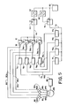
- Fig. 5 is a schematic diagram of an array of ink jet heads of the type shown in Fig. 1, together with a contaminant and air bubble purging system controlled by the circuit of Fig. 4.
- With reference to Figs. 1-3, an
ink jet head 10 includes abody 12 within which a singlecompartment ink chamber 14 and anair chamber 16 are provided. Theink chamber 14 is separated from theair chamber 16 by anink chamber wall 18. Also, theair chamber 16 is closed by anair chamber wall 20. Theink chamber 14 communicates with the air chamber through an internalink orifice passageway 22, which is provided through theink chamber wall 18. Theink orifice passageway 22 opens toair chamber 16 through on internal ink-drop-formingorifice outlet 23. An externalink jet orifice 24 passes from the air chamber to the exterior of theink jet head 10.Ink jet orifice 24 is axially aligned withink orifice passageway 22 andorifice outlet 23, as indicated byaxis 25. - In the case of Fig. 1,
ink chamber 14 is composed of twosections Section 28 is positioned adjacent to thewall 18 andink orifice passageway 22 and is also bounded by aninterior wall 32 of inkjet head body 12.Section 26 is of greater diameter thansection 28, and is bounded by aninterior wall 34. Thesections axis 25. - Ink under pressure is delivered to an
ink receiving inlet 36, flows through anink passageway 38, and fills theink chamber 14 within the ink jet head. - For purposes of facilitating the purging of contaminants and air bubbles from the ink jet head, as explained in greater detail below, ink is directed into the base of
ink chamber 14 so as to be tangential to thewall 34. Also, an inkchamber purging outlet 41, communicating through a purgingpassageway 40 withchamber section 28 adjacent the interior surface ofwall 18, is provided for use in selectively purging air bubbles and contaminants fromink chamber 14.Ink inlet passageway 38 and purgingpassageway 40 are positioned so that ink travels in a non-linear path between the inlet and purging outlet during the purging process. As explained below, this assists in sweeping air bubbles and contaminants from the ink chamber. More specifically, as indicated generally byarrow 42 in Fig. 3, ink travels in a vortical or cyclone-like path between theink inlet passageway 38 and the purgingpassageway 40. - The end of
ink chamber 14 oppositeink orifice outlet 22 is closed by a flexible membrane ordiaphragm 43, such as of stainless steel. Apiezoelectric crystal 44, together withmembrane 43, comprises one form of a pressure pulse generating actuator. In response to electrical pulses, a pressure wave is transmitted through theink chamber 14. This causes the ejection of an ink droplet from the ink-drop-formingorifice outlet 23 and toward theexternal orifice 24. - Pressurized air is delivered to an
air inlet 51 of theink jet head 10 and flows through apassageway 50 to theair chamber 16. Air is distributed about the circumference of the ink jet head between the outer surface ofink chamber wall 18 and the inner surface of theair chamber wall 20. More specifically, air flows inwardly from all directions through theair chamber 16 toward the center of the ink jet head. As air approaches the center of the head, it changes direction and flows outwardly through theexternal orifice 24. This air flow accelerates ink drops generated at ink-drop-formingorifice 23 in response to pressure pulses and assists in carrying them outwardly from the ink jet head. As a result, uniform and symmetrical ink drops are generated by the ink jet head. These drops travel through theexternal orifice 24 and toward the printing medium. Although not shown in Fig. 1, a projection, such as of conical shape, may be positioned on the outer surface ofink chamber wall 18. In such a case,ink orifice passageway 22 would pass through this projection and theink orifice outlet 23 would be located at the top of the projection. This projection assists in deflecting the air outwardly through theexternal orifice 24. - In a typical application, an exemplary air pressure is about 7.5 kPa (30 inH₂O) and an exemplary ink pressure is about 6.2 kPa (25 inH₂O). Thus, a typical pressure differential between the air and ink pressures is about 1.25 kPa (5 inH₂O). However, pressure differentials of from approximately 0.75 to 2.5 kPa (3 to 10 inH₂O) are suitable for optimum operation.
- The Fig. 1 form of ink jet head may be manufactured by simply laminating together sheets of material which have been drilled or fabricated with the appropriate openings. Because of this relatively simple manufacturing technique, it is extremely easy to align ink-drop-forming
orifice 23 and theexternal orifice 24. It is also easy to manufacture arrays of multiple ink jet heads. - A method and apparatus for purging contaminants and air bubbles from an ink jet head will next be described with reference to Figs. 4 and 5. This method and apparatus may be used in conjunction with a wide variety of ink jet heads, in addition to the ink jet head of Fig. 1. For example, it is suitable for air and non-air-assisted ink jet heads. This purging capability facilitates the initial filling of dry ink jet heads, the filling of ink jet heads which contain some ink, storage of ink jet heads, purging of bubbles and other contaminants from ink jet heads and the transportation of such heads. For example, conventional ink jet heads, when filled with ink and shipped at high altitudes by airline, are somewhat prone to outgassing of air bubbles into the ink within such ink jet heads. These bubbles can be very difficult to purge and also interfere with the performance of the ink jet head. Consequently, conventional ink jet heads must be packed and shipped with extreme care. By providing an easily accomplished method and apparatus for purging bubbles, any bubbles created during storage and shipment of an ink jet head can readily be removed. In addition, the illustrated method and apparatus permits in situ purging of contaminants and air bubbles from ink jet heads without the need from removing the heads from an ink jet printer. This minimizes down time for such printers and makes the entire purging procedure much easier. Moreover, the purging operation can be accomplished in only a few seconds. Also, purging typically requires only a very small fraction of the volume of ink in ink cartridges commonly used with ink jet heads.
- With reference to Fig. 5, an array of ink jet heads 10, 10a, 10b and 10c, such as the type in Fig. 1, is shown. During normal operation of this array, air under a positive pressure from an
air pump 60 is delivered through apressure regulator 62, through a closed solenoid controlled valve 64 (shown in a first position) to aline 66 and then to the air supply inlets of the respective ink jet heads. In addition, air frompump 60 passes through anotherregulator 68, through a solenoid controlledvalve 70, through aline 72, and to the air pressure side of a set of conventionalink jet cartridges - The ink delivery side of
cartridge 74 is connected through aline 76, aconventional bubble trap 78 and to theink supply inlet 36 ofink jet head 10. The ink supply sides of the cartridges 74a-74c are respectively coupled by lines 76a-76c, through bubble traps 78a-78c, and to the ink supply inlets 36a-36c of ink jet heads 10a-10c. The purging outlet ofink jet head 10 is coupled by aline 80 to one side of a normally closed purgingvalve 82. The other side ofvalve 82 is connected by aline 84 to apurging tank 86, which may be a closed vessel in which a vacuum is drawn by anoptional vacuum pump 88. In the same manner, the purging outlets of the ink jet heads 10a-10c are connected by respective lines 80a-80c to solenoid controlled valves 82a-82c. These latter valves are connected byrespective lines 84a-84c to thepurging tank 86. - During one purging process in accordance with the invention, solenoid controlled
valve 70 is shifted to a second position, shown in Fig. 7, so as to couple theair pump 60 to theline 72 and bypass thepressure regulator 68. This increases the pressure on ink in the ink cartridges 74-74c. An exemplary pressure increase is approximately 27.6 kPa (4 pounds-per-square-inch). This pressure increase produces a corresponding pressure increase at the respective ink supply inlets 36-36c and increases the pressure of the ink within the ink chambers of the ink jet heads. At the same time, although not necessarily so, the solenoid controlled valves 82-82c are opened to thereby open the purging outlets of each of the ink jet heads 10-10c. When this happens, ink flows from the ink supply inlet of each ink jet head, through the ink chambers and purging outlets of the heads, and to thepurging tank 86. In addition to the ink which exits via the purging outlets, a small amount of ink, for example, approximately 20 percent of the mass flow, will pass through theorifice passageway 22 of each of the ink jet heads. The resulting flow of ink through the ink chambers sweeps contaminants and bubbles from the chambers. Because the ink does not pass through a restricted orifice between the inlet and purging outlet, the velocity of ink flow through the ink chamber increases rapidly after purging is started and assists the purging process. - In addition, as previously explained, the Fig. 1 form of ink jet head has an
ink supply passageway 38 and a purgingpassageway 40 at opposite ends of the ink chamber from one another. These passageways are positioned such that the ink flows in a non-linear path through the ink chamber during purging. This facilitates the sweeping of contaminants and bubbles from the ink chamber. As shown in Fig. 3, by introducing the ink tangentially into theink chamber 14, the ink follows in a cyclone-like or vortical path through the ink chamber. This tends to sweep bubbles and contaminants clinging to the ink chamber walls from the ink chamber. In addition, by introducing the ink tangentially into the ink chamber and by removing the ink tangentially from the ink chamber, areas of low velocity ink flow or stagnation areas within the ink chamber are minimized. Consequently, areas of low dynamic pressure within the ink chamber are substantially eliminated during purging to enhance the effectiveness of the purging. Following purging for a few seconds, typically no more than from 2 to 20 seconds, valves 82-82c are closed to shut off the purging outlets.Valve 70 is also shifted to its first position so as to again deliver regulated air to the ink cartridges. During the purging operation,solenoid valve 64 may be shifted to its second position to vent air fromline 66. This prevents the delivery of air to the air chambers of ink jet heads 10-10c during the purging operation. - In addition to, or typically instead of, elevating the pressure within the ink cartridges during purging, the following purging method may be employed. In this alternate approach, the
vacuum pump 88 is employed to draw a vacuum, for example about negative 27.6 kPa (negative 4 pounds-per-square-inch) vacuum, invessel 86. During purging, the valves 82-82c are opened so that this negative pressure is applied to the purging outlets of the ink jet heads 10-10c. At the same time,valve 64 may be moved to its vent position andvalve 70 is typically left in the position shown in Fig. 5 so that a normal positive pressure exists at the ink inlet. Because of the negative pressure at the purging outlets, ink not only flows from the supply inlet of each ink jet head to the purging outlet, but the velocity of ink flow is increased. With this approach, very little ink typically flows through the ink orifice passageways. Consequently, the remote chance of forcing contaminants and bubbles into these passageways and clogging the ink jet heads during the purging operation is reduced. - As a further purging approach, an ink jet head which is wetted with fluid is drained through the purging outlet. When refilled, because the walls of the ink chamber are wetted (i.e. by ink or other fluid), removal of air bubbles during the purging operation is facilitated. For example, a dry ink jet head may be initially wetted and then purged in this manner. Alternately, an ink jet head which is wetted during normal operation may be drained and purged accordingly.
- Turning to Fig. 4, during normal operation of an ink jet head, drive signals, such as sinusoidal signals, at a desired frequency are obtained from a
conventional signal source 90. These signals are delivered through analog switches 92 and through ink jet amplifiers to the piezoelectric crystal of each ink jet head of an ink jet head array. To initiate a purging operation, aswitch 96 is closed to trigger amonostable multivibrator 98. When triggered, themultivibrator 98 produces an output to ink and airvalve solenoid drivers 100 and to the analog switches 92. While the monostable multivibrator is producing such an output signal,drivers 100 control thevalves source 90. When the monostable multivibrator output signal ends, the valves return to their normal position so that normal operation of the ink jet heads resumes. - As an additional option, a
purge signal source 102 may be provided. This source is coupled by the analog switches 92 to theink jet amplifiers 94 during the purging operation.Purge signal source 102 comprises aramp generator circuit 104 for applying a ramp voltage to a voltage controlledoscillator 106. In response to the ramp voltage output from the ramp generator, the voltage controlled oscillator produces a sinusoidal output which is varied from approximately 5 kHz to about 100 kHz. This sweeping frequency signal, when applied to the piezoelectric crystals of the ink jet heads, causes any bubbles in the ink chamber to oscillate. Oscillation is enhanced when the applied frequency is at the natural resonance frequency of the bubbles. As the bubbles oscillate, they tend to break up and dislodge from the walls of the ink chamber. This makes the bubbles easier to sweep from the ink chamber during the purging operation. Again, the frequency of the applied purging signal is continuously varied over a range, as compared to applying a few isolated purging signal frequencies. Because of this, virtually any bubble of significant size within the ink chamber will be subjected to an applied signal at the natural resonance frequency of the bubble. Consequently, removal of the bubbles is enhanced. It should be emphasized that successful purging typically is accomplished by the previously described purging operation without subjecting ink jet heads to a variable frequency purging signal. However, particularly when initially filling a dry ink jet head, in some cases the application of a variable frequency purging signal has removed bubbles that were not removed in the absence of such a signal. - Having illustrated and described the principles of our invention with reference to a preferred embodiment, it should be apparent to those persons skilled in the art that such invention may be modified in arrangement and detail without departing from such principles. We claim as our invention all such modifications as come within the scope of the following claims.
Claims (8)
- An ink jet printing apparatus comprising an ink jet head (10) having a body (12) that defines an internal ink chamber (14), an orifice passageway (22) leading from the ink chamber (14) and through which pressure pulses are transmitted in response to electrical signals applied to a piezoelectric crystal (44) which is in mechanical contact with ink in the ink chamber (14), an ink inlet (38) through which ink can be delivered to the ink chamber (14), and a purging outlet (40) through which ink can be removed from the ink chamber (14), the ink inlet (38) and the purging outlet (40) communicating with one another through the ink chamber (14) along a path that does not pass through the orifice passageway (22), the apparatus also comprising valve means (82) for selectively opening the purging outlet to permit flow of ink from the ink inlet (38) to the purging outlet (40), characterized in that the ink chamber (14) is substantially circular in cross section, the ink inlet (38) is disposed tangentially relative to the ink chamber (14), and the distance along the axis of the ink chamber from the ink inlet (38) to the purging outlet (40) is substantially less than the maximum diameter of the ink chamber, whereby ink flows along a cyclone-like path from the ink inlet (38) to the purging outlet (40) when the valve means (82) permit flow of ink from the ink inlet (38) to the purging outlet (40).
- An apparatus according to claim 1, characterized in that said distance is less than the maximum radius of the ink chamber (14).
- An apparatus according to claim 1 or 2, characterized in that the ink inlet (38) is at a first end of the ink chamber (14) and the purging outlet (40) is at a second end of the ink chamber (14), and the diameter of the ink chamber (14) decreases monotonically from the first end to the second end.
- An apparatus according to claim 1, 2 or 3, characterized in that the orifice passageway (22) is substantially coaxial with the ink chamber (14).
- An apparatus according to any one of claims 1-4, characterized by purging signal generator means (102) comprising variable voltage generator means (104) for producing a variable voltage output, and voltage controlled oscillator means (106) having an input for receiving the variable voltage output and for generating an electrical output signal of varying frequency, and further characterized by means (92) for selectively applying the electrical output signal to the piezoelectric crystal (44).
- An apparatus according to any one of claims 1-5, characterized by means (68, 70) for delivering ink at a first pressure to the ink chamber (14) while the purging outlet (40) is closed and for delivering ink to the ink chamber (14) at a second pressure, which is greater than the first pressure, during at least a portion of the time that the purging outlet (40) is open.
- An apparatus according to any one of claims 1-6, characterized by means (86, 88) for applying a negative pressure to the purging outlet (40) at least during a portion of the time that the purging outlet (40) is open.
- An apparatus according to any one of claims 1-7, characterized in that the ink orifice passageway (22) is formed in an ink chamber wall (18) and the ink jet head (12) has an air chamber wall (20) spaced from the ink chamber wall (18) by an air chamber (16) and formed with an external ink jet head orifice (24) in axial alignment with the ink orifice passageway (22), further characterized by means (60, 62) for supplying pressurized air to the air chamber (16) to assist the passage of ink drops from the external ink jet head orifice (24), and means (64) for selectively interrupting the flow of air to the air chamber (16) at least during a portion of the time that the purging outlet (40) is open.
Applications Claiming Priority (2)
| Application Number | Priority Date | Filing Date | Title |
|---|---|---|---|
| US06/884,846 US4727378A (en) | 1986-07-11 | 1986-07-11 | Method and apparatus for purging an ink jet head |
| US884846 | 1986-07-11 |
Publications (3)
| Publication Number | Publication Date |
|---|---|
| EP0252677A2 EP0252677A2 (en) | 1988-01-13 |
| EP0252677A3 EP0252677A3 (en) | 1988-12-28 |
| EP0252677B1 true EP0252677B1 (en) | 1992-10-07 |
Family
ID=25385549
Family Applications (1)
| Application Number | Title | Priority Date | Filing Date |
|---|---|---|---|
| EP87305820A Expired EP0252677B1 (en) | 1986-07-11 | 1987-07-01 | Ink jet printing apparatus |
Country Status (4)
| Country | Link |
|---|---|
| US (1) | US4727378A (en) |
| EP (1) | EP0252677B1 (en) |
| JP (1) | JPS6325048A (en) |
| DE (1) | DE3782101T2 (en) |
Families Citing this family (44)
| Publication number | Priority date | Publication date | Assignee | Title |
|---|---|---|---|---|
| GB2202799B (en) * | 1987-03-20 | 1991-09-18 | Canon Kk | Ink jet recording head and ink jet recording apparatus having the same |
| WO1988010192A1 (en) * | 1987-06-25 | 1988-12-29 | Siemens Aktiengesellschaft | Ink printing head with tangential-feed pressure chambers |
| GB8810241D0 (en) * | 1988-04-29 | 1988-06-02 | Am Int | Drop-on-demand printhead |
| JP2607274B2 (en) * | 1988-06-21 | 1997-05-07 | キヤノン株式会社 | Inkjet recording head |
| US4970535A (en) * | 1988-09-26 | 1990-11-13 | Tektronix, Inc. | Ink jet print head face cleaner |
| DE69022112T2 (en) * | 1989-05-18 | 1996-02-15 | Canon Kk | Ink jet recorder. |
| US5087930A (en) * | 1989-11-01 | 1992-02-11 | Tektronix, Inc. | Drop-on-demand ink jet print head |
| US5121130A (en) * | 1990-11-05 | 1992-06-09 | Xerox Corporation | Thermal ink jet printing apparatus |
| US5185614A (en) * | 1991-04-17 | 1993-02-09 | Hewlett-Packard Company | Priming apparatus and process for multi-color ink-jet pens |
| JP2998764B2 (en) * | 1991-06-13 | 2000-01-11 | セイコーエプソン株式会社 | Ink jet print head, ink supply method, and air bubble removal method |
| US5455615A (en) * | 1992-06-04 | 1995-10-03 | Tektronix, Inc. | Multiple-orifice drop-on-demand ink jet print head having improved purging and jetting performance |
| EP0573256B1 (en) * | 1992-06-04 | 1997-03-26 | Tektronix, Inc. | Drop-on-demand ink jet print head having improved purging performance |
| US5489925A (en) * | 1993-05-04 | 1996-02-06 | Markem Corporation | Ink jet printing system |
| DE69408082T2 (en) * | 1993-10-20 | 1998-09-10 | Tektronix Inc | Multi-ink jet head to be cleaned on demand and its mode of operation |
| EP0676289B1 (en) * | 1994-04-08 | 1999-02-10 | Hewlett-Packard Company | Wet-wiping technique for inkjet printhead |
| JP3332569B2 (en) * | 1994-04-26 | 2002-10-07 | キヤノン株式会社 | Liquid jet printing apparatus and printing method |
| US5596354A (en) * | 1994-10-03 | 1997-01-21 | Pitney Bowes Inc. | Ink priming device for ink jet printer |
| US5870126A (en) * | 1995-01-20 | 1999-02-09 | Hitachi Koki Co., Ltd. | Ink jet printer having bubble purge mechanism |
| US6572221B1 (en) * | 1997-10-10 | 2003-06-03 | Xaar Technology Limited | Droplet deposition apparatus for ink jet printhead |
| US6139136A (en) * | 1997-12-17 | 2000-10-31 | Pitney Bowes Inc. | Ink supply system including a multiple level ink reservoir for ink jet printing |
| US6460967B1 (en) | 1998-03-24 | 2002-10-08 | Konica Corporation | Liquid jetting apparatus |
| US6164752A (en) * | 1998-11-06 | 2000-12-26 | Xerox Corporation | Ink jet print head maintenance method |
| US6318851B1 (en) * | 1999-04-07 | 2001-11-20 | Hewlett-Packard Company | Method and system for purging air from a print mechanism |
| US6656432B1 (en) * | 1999-10-22 | 2003-12-02 | Ngk Insulators, Ltd. | Micropipette and dividedly injectable apparatus |
| GB0121625D0 (en) * | 2001-09-07 | 2001-10-31 | Xaar Technology Ltd | Droplet deposition apparatus |
| JP2004001338A (en) * | 2001-12-27 | 2004-01-08 | Seiko Epson Corp | Liquid jet head and method of manufacturing the same |
| US7188941B2 (en) * | 2004-01-07 | 2007-03-13 | Xerox Corporation | Valve for a printing apparatus |
| US7448734B2 (en) * | 2004-01-21 | 2008-11-11 | Silverbrook Research Pty Ltd | Inkjet printer cartridge with pagewidth printhead |
| US20050157112A1 (en) | 2004-01-21 | 2005-07-21 | Silverbrook Research Pty Ltd | Inkjet printer cradle with shaped recess for receiving a printer cartridge |
| US7510274B2 (en) * | 2005-01-21 | 2009-03-31 | Hewlett-Packard Development Company, L.P. | Ink delivery system and methods for improved printing |
| JP4710420B2 (en) * | 2005-05-31 | 2011-06-29 | セイコーエプソン株式会社 | Liquid distribution device and liquid ejection device |
| JP2007136989A (en) * | 2005-11-22 | 2007-06-07 | Ricoh Co Ltd | Image forming apparatus |
| US7520588B2 (en) * | 2005-12-23 | 2009-04-21 | Xerox Corp | Apparatus for reducing ink jet contamination |
| JP5082049B2 (en) * | 2006-09-26 | 2012-11-28 | セイコーエプソン株式会社 | Fluid ejecting apparatus and surgical tool |
| JP5200456B2 (en) * | 2007-09-03 | 2013-06-05 | 富士ゼロックス株式会社 | Droplet discharge device |
| JP4968040B2 (en) * | 2007-12-17 | 2012-07-04 | 富士ゼロックス株式会社 | Droplet discharge unit, droplet discharge head, and image forming apparatus having the same |
| JP5236523B2 (en) * | 2009-02-19 | 2013-07-17 | 株式会社ミマキエンジニアリング | Printer apparatus and maintenance method thereof |
| JP5248421B2 (en) * | 2009-06-22 | 2013-07-31 | ブラザー工業株式会社 | Liquid ejection device |
| US8517518B2 (en) | 2010-11-09 | 2013-08-27 | Canon Kabushiki Kaisha | Recording apparatus and liquid ejection head |
| US9039141B2 (en) * | 2012-05-10 | 2015-05-26 | Xerox Corporation | Fluidic structure that allows removal of air bubbles from print heads without generating waste ink |
| US9321071B2 (en) * | 2012-09-28 | 2016-04-26 | Amastan Technologies Llc | High frequency uniform droplet maker and method |
| US9242462B2 (en) * | 2013-12-03 | 2016-01-26 | Xerox Corporation | Single jet fluidic design for high packing density in inkjet print heads |
| US10195857B1 (en) | 2017-07-12 | 2019-02-05 | Xerox Corporation | Recovery of missing jets |
| JP7703395B2 (en) * | 2021-08-18 | 2025-07-07 | 株式会社ミマキエンジニアリング | Printing device and printing method |
Family Cites Families (17)
| Publication number | Priority date | Publication date | Assignee | Title |
|---|---|---|---|---|
| US4106032A (en) * | 1974-09-26 | 1978-08-08 | Matsushita Electric Industrial Co., Limited | Apparatus for applying liquid droplets to a surface by using a high speed laminar air flow to accelerate the same |
| US3974508A (en) * | 1974-12-16 | 1976-08-10 | Gould Inc. | Air purging system for a pulsed droplet ejecting system |
| JPS5177036A (en) * | 1974-12-27 | 1976-07-03 | Casio Computer Co Ltd | INKUFUN SHASOCHI |
| GB1527444A (en) * | 1977-03-01 | 1978-10-04 | Itt Creed | Ink drop printhead |
| JPS54159227A (en) * | 1978-06-06 | 1979-12-15 | Ricoh Co Ltd | Ink jet recorder |
| JPS55121074A (en) * | 1979-03-14 | 1980-09-17 | Canon Inc | Removing method of air bubble |
| DE2927488A1 (en) * | 1979-07-07 | 1981-01-22 | Philips Patentverwaltung | INK-JET PRINTER |
| JPS5675867A (en) * | 1979-11-22 | 1981-06-23 | Seiko Epson Corp | Ink jet recorder |
| JPS5682266A (en) * | 1979-12-08 | 1981-07-04 | Ricoh Co Ltd | Ink supply passage for ink jet recording device |
| US4380018A (en) * | 1980-06-20 | 1983-04-12 | Sanyo Denki Kabushiki Kaisha | Ink droplet projecting device and an ink jet printer |
| US4367479A (en) * | 1980-11-03 | 1983-01-04 | Exxon Research And Engineering Co. | Method and apparatus for purging and/or priming an ink jet |
| JPS5818273A (en) * | 1981-07-27 | 1983-02-02 | Sharp Corp | Removal of air from ink jet nozzle |
| DE3247540A1 (en) * | 1981-12-26 | 1983-07-07 | Konishiroku Photo Industry Co., Ltd., Tokyo | INK PENS |
| JPS58194564A (en) * | 1982-05-11 | 1983-11-12 | Canon Inc | Ink jet printer |
| US4518974A (en) * | 1982-09-21 | 1985-05-21 | Ricoh Company, Ltd. | Ink jet air removal system |
| US4533569A (en) * | 1983-12-08 | 1985-08-06 | Ncr Corporation | Process preventing air bubble lock in ink jet nozzles |
| JPH106871A (en) * | 1996-06-21 | 1998-01-13 | Suzuki Motor Corp | Jack handle storage structure |
-
1986
- 1986-07-11 US US06/884,846 patent/US4727378A/en not_active Expired - Lifetime
-
1987
- 1987-07-01 DE DE8787305820T patent/DE3782101T2/en not_active Expired - Fee Related
- 1987-07-01 EP EP87305820A patent/EP0252677B1/en not_active Expired
- 1987-07-08 JP JP62170852A patent/JPS6325048A/en active Pending
Also Published As
| Publication number | Publication date |
|---|---|
| DE3782101D1 (en) | 1992-11-12 |
| JPS6325048A (en) | 1988-02-02 |
| EP0252677A2 (en) | 1988-01-13 |
| US4727378A (en) | 1988-02-23 |
| DE3782101T2 (en) | 1993-05-06 |
| EP0252677A3 (en) | 1988-12-28 |
Similar Documents
| Publication | Publication Date | Title |
|---|---|---|
| US4727378A (en) | Method and apparatus for purging an ink jet head | |
| US4728969A (en) | Air assisted ink jet head with single compartment ink chamber | |
| US6250752B1 (en) | Ink supply device and ink-jet recording head with filter and shaped flow passage | |
| EP0467656B1 (en) | Method of operating an on-demand ink jet print head | |
| US4613875A (en) | Air assisted ink jet head with projecting internal ink drop-forming orifice outlet | |
| EP0645244A1 (en) | Ink jet head and ink jet recording apparatus having same | |
| EP0011171B1 (en) | Liquid droplet forming apparatus | |
| WO2008045235A1 (en) | Continuous drop emitter with reduced stimulation crosstalk | |
| JPS638908B2 (en) | ||
| US4188635A (en) | Ink jet printing head | |
| JP2000218829A (en) | Self-cleaning ink jet printhead cartridge | |
| US6394589B1 (en) | Ink jet printhead with reduced crosstalk | |
| US4703330A (en) | Color ink jet drop generator using a solid acoustic cavity | |
| JPS62184861A (en) | Ink jet drip generator | |
| US4641155A (en) | Printing head for ink jet printer | |
| EP0054114B1 (en) | Liquid droplet forming apparatus | |
| JPH10507701A (en) | Inkjet printer | |
| EP0011170B1 (en) | Liquid droplet forming apparatus | |
| JPH07195711A (en) | Inkjet recording device | |
| JPS62105636A (en) | Droplet generator for inkjet printers | |
| JPH02209245A (en) | Printing device | |
| JPH09174836A (en) | Ink jet recording head and manufacture thereof | |
| JPS6422556A (en) | Drop generator of on-demand type ink jet head | |
| KR20010005335A (en) | A bubble removable apparatus of inkjet printhead | |
| JPS63172656A (en) | Inkjet recording device head |
Legal Events
| Date | Code | Title | Description |
|---|---|---|---|
| PUAI | Public reference made under article 153(3) epc to a published international application that has entered the european phase |
Free format text: ORIGINAL CODE: 0009012 |
|
| AK | Designated contracting states |
Kind code of ref document: A2 Designated state(s): DE FR GB NL |
|
| PUAL | Search report despatched |
Free format text: ORIGINAL CODE: 0009013 |
|
| AK | Designated contracting states |
Kind code of ref document: A3 Designated state(s): DE FR GB NL |
|
| 17P | Request for examination filed |
Effective date: 19890603 |
|
| 17Q | First examination report despatched |
Effective date: 19901011 |
|
| GRAA | (expected) grant |
Free format text: ORIGINAL CODE: 0009210 |
|
| AK | Designated contracting states |
Kind code of ref document: B1 Designated state(s): DE FR GB NL |
|
| REF | Corresponds to: |
Ref document number: 3782101 Country of ref document: DE Date of ref document: 19921112 |
|
| ET | Fr: translation filed | ||
| PG25 | Lapsed in a contracting state [announced via postgrant information from national office to epo] |
Ref country code: GB Effective date: 19930701 |
|
| PLBE | No opposition filed within time limit |
Free format text: ORIGINAL CODE: 0009261 |
|
| STAA | Information on the status of an ep patent application or granted ep patent |
Free format text: STATUS: NO OPPOSITION FILED WITHIN TIME LIMIT |
|
| 26N | No opposition filed | ||
| PG25 | Lapsed in a contracting state [announced via postgrant information from national office to epo] |
Ref country code: NL Effective date: 19940201 |
|
| GBPC | Gb: european patent ceased through non-payment of renewal fee |
Effective date: 19930701 |
|
| NLV4 | Nl: lapsed or anulled due to non-payment of the annual fee | ||
| PG25 | Lapsed in a contracting state [announced via postgrant information from national office to epo] |
Ref country code: FR Effective date: 19940331 |
|
| PG25 | Lapsed in a contracting state [announced via postgrant information from national office to epo] |
Ref country code: DE Effective date: 19940401 |
|
| REG | Reference to a national code |
Ref country code: FR Ref legal event code: ST |