EP0252584A1 - Tiefgefriertunnel für Nahrungsmittel - Google Patents
Tiefgefriertunnel für Nahrungsmittel Download PDFInfo
- Publication number
- EP0252584A1 EP0252584A1 EP87303756A EP87303756A EP0252584A1 EP 0252584 A1 EP0252584 A1 EP 0252584A1 EP 87303756 A EP87303756 A EP 87303756A EP 87303756 A EP87303756 A EP 87303756A EP 0252584 A1 EP0252584 A1 EP 0252584A1
- Authority
- EP
- European Patent Office
- Prior art keywords
- tunnel
- trough
- trough member
- roof
- counterweights
- Prior art date
- Legal status (The legal status is an assumption and is not a legal conclusion. Google has not performed a legal analysis and makes no representation as to the accuracy of the status listed.)
- Withdrawn
Links
- 235000013305 food Nutrition 0.000 title claims abstract description 36
- 230000008014 freezing Effects 0.000 title claims abstract description 17
- 238000007710 freezing Methods 0.000 title claims abstract description 17
- 238000009834 vaporization Methods 0.000 claims description 3
- 238000004140 cleaning Methods 0.000 abstract description 3
- IJGRMHOSHXDMSA-UHFFFAOYSA-N Atomic nitrogen Chemical compound N#N IJGRMHOSHXDMSA-UHFFFAOYSA-N 0.000 description 59
- 229910052757 nitrogen Inorganic materials 0.000 description 29
- 239000007788 liquid Substances 0.000 description 27
- 239000007789 gas Substances 0.000 description 21
- 230000000295 complement effect Effects 0.000 description 12
- 239000007921 spray Substances 0.000 description 11
- CURLTUGMZLYLDI-UHFFFAOYSA-N Carbon dioxide Chemical compound O=C=O CURLTUGMZLYLDI-UHFFFAOYSA-N 0.000 description 6
- 238000007789 sealing Methods 0.000 description 6
- 238000010276 construction Methods 0.000 description 4
- 230000005484 gravity Effects 0.000 description 4
- 230000015572 biosynthetic process Effects 0.000 description 3
- 229910002092 carbon dioxide Inorganic materials 0.000 description 3
- 239000001569 carbon dioxide Substances 0.000 description 3
- 238000001816 cooling Methods 0.000 description 2
- 230000003670 easy-to-clean Effects 0.000 description 2
- 230000004048 modification Effects 0.000 description 2
- 238000012986 modification Methods 0.000 description 2
- 238000005728 strengthening Methods 0.000 description 2
- 241000287828 Gallus gallus Species 0.000 description 1
- 229920005830 Polyurethane Foam Polymers 0.000 description 1
- 230000004308 accommodation Effects 0.000 description 1
- 238000009825 accumulation Methods 0.000 description 1
- 230000004888 barrier function Effects 0.000 description 1
- 230000008602 contraction Effects 0.000 description 1
- 230000001276 controlling effect Effects 0.000 description 1
- 230000008021 deposition Effects 0.000 description 1
- 229910001873 dinitrogen Inorganic materials 0.000 description 1
- 238000001704 evaporation Methods 0.000 description 1
- 230000008020 evaporation Effects 0.000 description 1
- 239000012530 fluid Substances 0.000 description 1
- 238000011010 flushing procedure Methods 0.000 description 1
- 235000013611 frozen food Nutrition 0.000 description 1
- 235000015220 hamburgers Nutrition 0.000 description 1
- 238000010438 heat treatment Methods 0.000 description 1
- 230000008595 infiltration Effects 0.000 description 1
- 238000001764 infiltration Methods 0.000 description 1
- 238000009413 insulation Methods 0.000 description 1
- 238000000034 method Methods 0.000 description 1
- 239000011496 polyurethane foam Substances 0.000 description 1
- 238000005057 refrigeration Methods 0.000 description 1
- 230000001105 regulatory effect Effects 0.000 description 1
- 230000000717 retained effect Effects 0.000 description 1
- 229910001220 stainless steel Inorganic materials 0.000 description 1
- 239000010935 stainless steel Substances 0.000 description 1
- 235000013311 vegetables Nutrition 0.000 description 1
Images


Classifications
-
- F—MECHANICAL ENGINEERING; LIGHTING; HEATING; WEAPONS; BLASTING
- F25—REFRIGERATION OR COOLING; COMBINED HEATING AND REFRIGERATION SYSTEMS; HEAT PUMP SYSTEMS; MANUFACTURE OR STORAGE OF ICE; LIQUEFACTION SOLIDIFICATION OF GASES
- F25D—REFRIGERATORS; COLD ROOMS; ICE-BOXES; COOLING OR FREEZING APPARATUS NOT OTHERWISE PROVIDED FOR
- F25D3/00—Devices using other cold materials; Devices using cold-storage bodies
- F25D3/10—Devices using other cold materials; Devices using cold-storage bodies using liquefied gases, e.g. liquid air
- F25D3/11—Devices using other cold materials; Devices using cold-storage bodies using liquefied gases, e.g. liquid air with conveyors carrying articles to be cooled through the cooling space
-
- A—HUMAN NECESSITIES
- A23—FOODS OR FOODSTUFFS; TREATMENT THEREOF, NOT COVERED BY OTHER CLASSES
- A23B—PRESERVATION OF FOODS, FOODSTUFFS OR NON-ALCOHOLIC BEVERAGES; CHEMICAL RIPENING OF FRUIT OR VEGETABLES
- A23B2/00—Preservation of foods or foodstuffs, in general
- A23B2/80—Freezing; Subsequent thawing; Cooling
- A23B2/85—Freezing; Subsequent thawing; Cooling with addition of or treatment with chemicals
- A23B2/88—Freezing; Subsequent thawing; Cooling with addition of or treatment with chemicals with direct contact between the food and the chemical, e.g. liquid N2 at cryogenic temperature
Definitions
- This invention relates to apparatus suitable for freezing food.
- liquid nitrogen and, to a lesser extent liquid carbon dioxide are widely used to freeze food.
- a common method of employing the liquid nitrogen or liquid carbon dioxide to freeze food is to advance the food to be frozen on an endless conveyor through a tunnel into which the liquefied gas is sprayed. Heat exchange takes place between the liquefied gas and the food and also between the food and the cold gas that is formed as a result of the vaporisation of the liquid. Fans are typically employed to promote the heat exchange between the cold gas and the food.
- Food freezing tunnels are, for example, described in U.K. patent specification 2 076 952 B and U.S. patent specification No. 4 l7l 625.
- a food freezing tunnel It is desirable for a food freezing tunnel to be easy to clean. Thus, access should be readily gained after a food freezing operation to the interior of the tunnel. Accordingly, some tunnels are formed with hinged panels on their sides which can be unlatched and raised or lowered manually to enable cleaning hoses and the like to be inserted therethrough. However, the access afforded to its interior by such a tunnel is limited, and difficulties can sometimes arise in achieving effective latching and sealing Alternative tunnels have means for lifting the roof away from the trough. Some of these tunnels have seals that are positioned near the bottom thereof and are thus likely to be directly impinged upon by the liquid nitrogen sprays. Other such tunnels employ relatively complex roof constructions that are difficult to fabricate or involve complex lifting arrangements. Moreover, such tunnels can be unsuitable for use in a factory with a low ceiling.
- Another tunnel of this kind substitutes pneumatic actuators for the hydraulic ones.
- the use of such pneumatic actuators means that a pneumatic pressure needs to be applied to the actuators throughout the period in which the trough member is in its raised position.
- the pneumatic actuators restrict the height available for downward travel of the trough member and difficulties can arise in operating them in unison with the result that damage can be done to the carcass of the trough member.
- the pneumatic actuators are single acting in the upward direction. Gravity is used to lower the trough, so delay may be caused by ice deposited between the engaging surfaces of the roof and trough during operation of the tunnel, with the result that the ice has first to melt before the trough can be lowered.
- apparatus suitable for freezing food comprising a tunnel defined by a trough member and a separate roof member; a conveyor extending through the tunnel from its entrance to its exit and having an upper run and a lower run; means for introducing liquefied gas into the tunnel; means for creating in the tunnel turbulence in cold gas formed as a result of vaporisation of the liquefied gas; at least one mechanical means for raising and lowering the trough member between an upper position in which the trough member engages the roof member and a lower position in which the trough member is spaced from the roof member, said mechanical means having a single or common drive, said trough member having counterweights, and the trough and roof members being adapted to engage one another at a level above that of the upper conveyor run.
- the plurality of mechanical means comprises a plurality of jacks. It is further preferred that just two jacks be employed.
- Each jack typically includes a vertical rotary screw and a nut adapted to travel along said screw on rotation of the worm, the nut being connected directly or indirectly to the trough member.
- the trough is connected or secured indirectly to the nut, for example by means of a chain or like tensile member. Such chain may extend around at least one pulley.
- both jacks preferably having screws with axes that lie in a plane vertical to the longitudinal axis of the tunnel typically but not necessarily at approximately the midpoint of the tunnel.
- the jacks and counterweights and the drive means may all be mounted within hollow parts of a frame supporting the tunnel, thus protecting them from damage and not restricting downward travel of the trough member when such member is in its upper position.
- the invention provides a relatively lifting mechanism for the trough member in comparison with known pneumatic and hydraulic means.
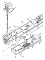
- a food product freezing tunnel l0 including an elongate tunnel housing ll through which a food product conveyor l2 extends from a food product entrance end l4 to an exit end l5.
- a liquid nitrogen spray header l6 or other suitable liquid nitrogen introduction means is provided for introducing liquid nitrogen into the tunnel l0.
- the spray header l6 is located near the tunnel exit l5.
- an exhaust plenum l7 is connected to an exhaust stack l8 that extends up through the roof l9 of the building in which the tunnel is located.
- An exhaust blower 2l is mounted at the top of the stack l8. In the illustrated construction, there is a rain-proof housing 22 over the top of the stack l8. In operation, the blower 2l exhausts to the atmosphere in the direction of arrow A nitrogen in the tunnel l0.
- the tunnel l0 further includes a plurality of turbulence fans 24 arranged in two rows along the length of the tunnel.
- the fans 24 are employed if desired in conjunction with a series of associated baffles (not shown), though if desired the baffles (not shown) may be omitted, to create turbulence in the nitrogen vapour formed by evaporation of the liquid nitrogen sprayed into the tunnel, and thus to facilitate cooling of food product 26 as the food product is conveyed through the tunnel by the conveyor l2.
- the food product 26 may comprise hamburger patties, steaks, chicken pieces, vegetable patties, or other food products that are able successfully to be frozen.
- blower 27 At an intermediate location within the tunnel, preferably about midway between the spray header l6 and the exhaust plenum l7, there is a variable speed directional blower 27.
- the blower 27 effectively controls the proportionate flow of nitrogen vapour or gas towards the entrance and exit ends of the tunnel.
- increasing the speed of blower 27 increases the flow of gas toward the food product entrance l4, which is also the gas exhaust end of the tunnel l0.
- a liquid nitrogen supply (not shown) is connected to the tunnel l0 through a liquid nitrogen supply pipe 3l provided with a thermally-insulating jacket 32.
- the liquid nitrogen supply pipe 3l is also provided with a pneumatically actuated regulating valve 33 to control the flow of liquid nitrogen into the tunnel l0 through the spray header l6.
- a temperature sensor 34 is positioned in the tunnel housing ll, preferably at a location intermediate the spray header l6 and directional blower 27, and is connected to a control system (not shown) that controls the rate of introduction of liquid nitrogen into the tunnel l0 by controlling the operation of the valve 33.
- the tunnel l0 is generally conventional; it is similar to the food product freezing tunnel described in detail in U.S. patent No. 4 l7l 625.
- the food product 26 is deposited on conveyor l2 at the entrance end l4 of the tunnel housing ll.
- it is progressively chilled by cold nitrogen gas that is brought into contact with it by operation of the circulation fans 24 and baffles 25.
- the spray header l6 it is already quite cold and may be starting to freeze at its surface.
- the food product is subjected to an intense spray of liquid nitrogen and freezing is completed quite rapidly.
- the frozen food product 26 is discharged from the exit end l5 of the tunnel l0.
- the speed of directional blower 27 may be varied to accommodate changing conditions within the tunnel, such as a variation in the rate of product flow. This has most often been accomplished by sensing the rate of flow of liquid nitrogen into the tunnel and adjusting the blower speed as a direct function of the liquid nitrogen flow rate.
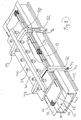
- the tunnel housing ll comprises a fixed elongate roof member 40 and a lower complementary elongate trough member 42 which is able to be displaced from an upper position (as shown in Figures 2 and 4) in which it engages the roof member 40, this position being the one that the trough member 42 has in normal use of the tunnel l0 to freeze food products, to a lower position (as shown in Figure 3) in which the trough member 42 is apart from the roof member 40, this position being the one that the trough member 42 has when the tunnel is to be cleaned.
- the means provided for raising and lowering the trough member 42 will be described below.
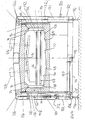
- the trough member 42 comprises (as shown in Figure 5) an inner skin 44, an outer skin 46, and thermal insulation 48 such as expanded polyurethane foam filling the space between the inner and outer skins 44 and 46 respectively.
- the skins 44 and 46 may comprise relatively thin gauge stainless steel sheet.
- the trough member 42 has generally vertical elongate sides 50.
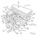
- each side 50 has a top face 52 sharing a common edge 56 (see Figure 6) with a sloping internal face 54 that slopes downwards a short distance from the edge 56 to an edge 58 (see Figure 6) of a generally vertical surface 60.
- the faces 52 and 54 when the trough member 42 is in its upper position engage complementary faces 62 and 64, respectively, of the roof member 40. The engagement is not gas-tight but any leakage of gas from the interior of the tunnel l0 between the engaging faces to the exterior of the tunnel l0 is minimal in its operation to freeze food products.
- no elastomeric or like sealing member is engaged between the faces 52 and 54 on the one hand and the complementary faces 62 and 64 on the other hand, although, if desired, such a sealing member may be employed.
- electrically heated tapes may be disposed at chosen locations along but within the faces 52 and 54 so as to be effective to prevent the accumulation of ice on the external surfaces.
- the tunnel is constructed so as to impede the flow of liquid nitrogen or its cold vapour towards the engaging faces of the roof member 40 and the trough member 42 and thereby limit the rate of formation of ice between the engaging members and thereby limit the rate of formation of ice between the engaging members.
- the engaging surfaces of the roof member 40 and trough member 42 are at a level above the upper run 66 of the conveyor belt l2. These surfaces are thus in a position such that spray from the overhead spray-header l6 is directed away from them. There is thus substantially no risk of direct impingement of the liquid nitrogen on these engaging surfaces in operation of the tunnel l0.
- the trough section 42 is provided with a complementary inner trough or sleeve 70 (or 'liner' as we sometimes also call it) which extends from near the entrance and of the tunnel l0 to near the exit end thereof.
- a freezing tunnel having such an inner trough is the subject of our copending application entitled 'Food freezing apparatus' of the same date as this application.
- the sleeve is located between the inner surface of the trough member 42 and the lower run 68 of the conveyor belt l2. (For ease of illustration the belt l2 is omitted from Figure 6.)
- the sleeve 70 is not able to extend for the whole length of the tunnel l0, its extent at the exit end being limited by the catenary of the belt.
- the flow regime is arranged so as to keep down the flow of cold nitrogen out of the end of the sleeve 70 near the exit end l5 of the tunnel, but such cold nitrogen that does follow such a path will be withdrawn by the exhaust blower 2l as the plenum l7 communicates with the space defined between the sleeve 70 and the trough member 42. Moreover, at the entrance end l4 of the tunnel, the interior of the sleeve 70 exhausts into the plenum l7.
- the sleeve 70 has sides 72 spaced from and complementary to the sides 50 of the trough member 42. At the top of each side 72, the sleeve 70 is demountably attached to a resilient or springy elongate, L-shaped rail 74 which is fixed to a complementary downward projection or lug 76 from the roof member 40.
- the sides of the sleeve 70 preferably make a substantially gas tight seal with the respective rails 74 such that in operation of the tunnel the flow of cold gas from within the sleeve 70 through the seals between the tops of the sides 72 and the rails 74 is substantially prevented and thus the main route for passage or infiltration of cold gas from within the sleeve 70 to the space between the sleeve 70 and the inner surfaces of the trough member 42 is along the interior of the sleeve and out through its ends.
- the sleeve 70 thus acts as a considerable barrier to the flow of cold gas from the vicinity of the spray-header l6 to the inner surfaces of the trough member 42.
- the sides 72 of liner or sleeve 70 are hinged in the longitudinal direction at 78.
- This construction enables access to be gained at the innermost parts of the tunnel once the trough member 42 has been lowered.
- the sides 72 of the sleeve 70 may be detached from the rails 74.
- latches (not shown) may be employed to attach the sides 72 of the sleeve 70 to the rails 74.)
- the sides 72 may then be lowered from their vertical position as shown in Figures 2, 4 and 6 to the generally horizontal position shown in Figure 3.
- the tunnel l0 has a frame 80 with legs 82 that serves to support the weight of the tunnel. As shown in Figure 3, those parts 84 of the sides 72 of the sleeve 70 that are adjacent the legs 82 are not hinged. Preferably, the hinged sections of the sides 72 when in their upright portions engages the respective fixed parts 84 in a substantially gas tight manner so as to minimise the flow of gas therebetween.
- the rod 86 is adapted to support the upper belt run (not shown in Figure 6) and the rod 88 to support the lower belt run (not shown in Figure 6).
- the rods 86 and 88 extend between a pair of hangers 90 (only one of which is shown in Figure 6) which are fixed to the respective projections 76 on either side of the longitudinal axis of the tunnel l0.
- the hangers 90 are also employed to support the sleeve 70.
- Each hanger 90 has an inclined inwardly-extending flange 92 to which a complementary face of the sleeve 70 is bolted or otherwise secured.
- the sleeve 70 is thus independent of the trough member 42 and thus remains in the position shown in, for example, Figure 6 when the trough member 42 is lowered.
- the frame comprises a plurality of pairs of opposed legs 82.
- the legs 82 are mounted on adjustable feet 94.
- Each pair of opposed legs 82 is connected by a lower cross-beam 96 and are welded or otherwise secured to upper cross-members 98 which in turn are welded or otherwise secured to the respective sides of a longitudinal beam l00.
- the roof member 40 is secured to the cross-members 98.
- All the legs 82 on one side of the tunnel l0 have a longitudinal strengthening member l02 extending therethrough and an analogous strengthening member l04 is provided for the legs on the other side of the tunnel.
- the legs 82, cross-beams 96, cross-members 98 and longitudinal beam l00 are all typically hollow. There is preferably one pair of legs 82 and associated cross-beam 96 and cross-members 98 at or near one end of the tunnel, and another pair of legs 82 and associated cross-beam 96 and cross-members 98 at or near the other end of the tunnel.
- the longitudinal spacing between adjacent legs of the tunnel is in order of l0ft.
- each of the central pair of legs 82 houses in its hollow interior mechanical means effective to raise and lower the trough section 42 and the rest of the legs carry counterweights to facilitate the raising and lowering of the trough section 42.
- the legs of one of the two more central pairs each houses in its hollow interior mechanical means effective to raise and lower the trough section 42 and the rest of the legs carry counterweights to facilitate the raising and the lowering of the trough section 42.
- a cross-beam 96 houses an electric (DC) motor l05 which drives a pair of horizontal shafts l07 extending out of opposite ends of the motor housing. (Only one shaft is shown in Figure 4.)
- Each shaft l04 at its end remote from the motor l02 extends into and ends in the interior of a leg 82 joined to the cross-beam 96 having the motor l05 and shaft l07.
- the end of each shaft carries a suitable worm wheel (not shown) which co-operates with a complementary pinion l06 mounted on the vertical screw-threaded shaft ll0 of jack means l08 housed in the respective leg 82.
- Each shaft ll0 carries a complementary screw-threaded nut ll2 to which is secured one link of a chain ll4 that extends around upper and lower pulley wheels ll6 and ll8 housed within the frame 80. Another part of the chain is secured to a flange l20 extending outwards from the trough member 42.
- the arrangement is that the part of the chain ll4 that is secured to the trough member 42 is on the opposite side of the pulley wheel ll6 and ll8 to the link that is secured to the nut ll2.
- the motor l05 the trough member 42 may be jacked up and down.
- the motor l05 rotates the shaft l07 which in turn rotates the screw-threaded shaft ll0, thereby causing the screw-threaded nuts ll2 to travel up or down the shafts ll0 according to the direction of rotation of the shafts ll0. Travel of each nut ll2 up its shaft ll0 pulls the chain ll4 in a clockwise direction, thereby lowering the trough section 42. By reversing the direction of rotation of the motor l05, each nut ll2 may be caused to travel down the shaft ll0 thereby raising the trough member 42 into engagement with the roof member 40. Limit switches (not shown) may be employed to deactivate the electric motor l05 when the trough section reaches its topmost and bottommost positions.
- Each counterweight comprises a hollow container l2l which is able to be filled with lead shot or other kind of weights. (The counterweights may alternatively each comprise a support rod onto which weights can be loaded.)
- the upper end of the container l2l is secured to one end of a length of chain l22 which extends over a pulley wheel l24 located within the frame 80 and which at its other end is secured to a flange l26 projecting from the side of the trough member 42.
- the counterweights oppose any tendency for the ends of the trough member to fall, when being lowered, at a greater speed than the centre of the tunnel, that is they resist any tendency for the trough member to buckle or bow during lowering. Similarily, when the trough section 42 is raised again, the weight of the counterweights tends to assist the upward travel of the trough member 42, thus keeping down the amount of power that the motor l02 needs to apply in order to raise the trough member 42, thereby adding to the safety of the tunnel.
- the trough member 42 Since the trough member 42 has a centre of gravity that lies on an axis remote from the axes of the wormed shafts ll0, during periods in which the electric motor l02 is not operated each nut ll2 will naturally be locked in position in its shaft ll0, and accordingly the trough member will be held firm. Moreover, when the trough member 42 is in its upper position, the counterweights apply a bias to the trough member which helps to maintain a fluid-tight seal between it and the roof member 40.
- the floor of the trough section 42 slopes from entrance to exit, or vice versa, at a small angle to the horizontal, say, a half a degree or one degree.
- the floor 43 of the trough section 42 and the floor 7l of the sleeve 70 may be provided with inclined surfaces l28 and l30, respectively, that slope downwards from the sides 50 and 72, respectively, towards the longitudinal axis of the floor of the trough section 42.
- the tunnel may also be provided with guides l32 on its legs 82 so as to guide the upwards and downwards travel of the trough member 42.
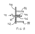
- the hanger 90 are each formed in two pieces l40 and l42.
- the piece l40 carries one end on upper conveyor belt support rod 86 and the piece l42 carries the corresponding end of a lower conveyor belt support rod 88.
- the pieces l40 and l42 have complementary flanges l44 and l46 respectively, between which the sleeve 70 extends.
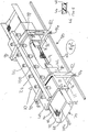
- FIG. 9 which illustrates the lifting mechanism for the trough, with the trough, roof member, and the supporting framework of the tunnel all not shown, for the sake of clarity of illustration, there are two longitudinal shafts l50 extending parallel to one another.
- One shaft l50 supports those of the pulleys ll6 and l24 on one side of the tunnel, while the other shaft l50 supports the remaining pulleys ll6 and l24 on the other side of the tunnel.
- the driven screw-threaded shafts ll0 can be located at any pair of tunnel legs.
- the most convenient pair of legs for such location of the drive mechanism is at the (food) exit and of the tunnel where owing to the slope of the trough the clearance between the trough in its lowered position and the floor is the greatest, thus facilitating accommodation of motor l05.
- the shafts l24 ensure synchronisation of the movement of the counterweights l2l and prevent any tendency for the trough to slew.
- the pulleys ll6, ll8 and l24 are typically formed as sprockets.
- the shafts l50 are preferably accommodated in longitudinal hollow beams (not shown) similar to the beams l02. There is a single drive shaft l07 with a chain drive l52 from motor l05 which runs off alternating current l07. Plates or blocks l54 are provided to attach the counterweights l2l to the trough (not shown in Figure 9).
- FIG l0 there is shown an embodiment of the tunnel in which the inner trough 70 passes between belt runs in the manner shown in Figure 7.
- the hinged sides 72 of the trough are provided with projecting members l67 which bear against the respective walls 50 of the trough 42. Accordingly, there is a positive pressure exerted by the sides 72 on the abutting arm of the rail 74 when the tunnel is in its upper position, thereby providing a substantially gas tight seal between each hinged side 72 and its adjacent rail 74.
- An advantage of this arrangement is that as the tunnel is cooled down in operation, differential contraction of the inner and outer skins of the trough member which tends to reduce the gap between the walls 50 and the side 72, increases the pressure in the members l67, thus improving the gas sealing.
- the trough 42 is in its upper, or operating, position there is no direct contact between the roof member 40 and the trough member 42 and in particular there is a clearance between the faces 52 and 54 of the trough member 42 and the complementary faces of the roof member 40.
- each rail 74 slopes from top to bottom toward the adjacent side 50 of the trough member 42 so as to facilitate its engagement with the adjacent side 72 of the trough 70.
- Cover strips l69 are provided on the roof edges to minimise air flow into the space between the roof 40 and the inner trough 70.
- the cover strips may be flexible and if desired contain an elastomeric seal.
Landscapes
- Engineering & Computer Science (AREA)
- Chemical & Material Sciences (AREA)
- Life Sciences & Earth Sciences (AREA)
- Polymers & Plastics (AREA)
- Zoology (AREA)
- Food Science & Technology (AREA)
- Wood Science & Technology (AREA)
- Combustion & Propulsion (AREA)
- Physics & Mathematics (AREA)
- Mechanical Engineering (AREA)
- Thermal Sciences (AREA)
- General Engineering & Computer Science (AREA)
- Freezing, Cooling And Drying Of Foods (AREA)
Applications Claiming Priority (2)
| Application Number | Priority Date | Filing Date | Title |
|---|---|---|---|
| GB868611538A GB8611538D0 (en) | 1986-05-12 | 1986-05-12 | Food freezing tunnel |
| GB8611538 | 1986-05-12 |
Publications (1)
| Publication Number | Publication Date |
|---|---|
| EP0252584A1 true EP0252584A1 (de) | 1988-01-13 |
Family
ID=10597730
Family Applications (1)
| Application Number | Title | Priority Date | Filing Date |
|---|---|---|---|
| EP87303756A Withdrawn EP0252584A1 (de) | 1986-05-12 | 1987-04-28 | Tiefgefriertunnel für Nahrungsmittel |
Country Status (6)
| Country | Link |
|---|---|
| US (1) | US4782668A (de) |
| EP (1) | EP0252584A1 (de) |
| JP (1) | JP2628995B2 (de) |
| AU (1) | AU7271987A (de) |
| GB (1) | GB8611538D0 (de) |
| ZA (1) | ZA873247B (de) |
Cited By (2)
| Publication number | Priority date | Publication date | Assignee | Title |
|---|---|---|---|---|
| EP0667502A1 (de) * | 1994-02-15 | 1995-08-16 | Air Products And Chemicals, Inc. | Gefriertunnel |
| WO1996000371A1 (en) * | 1994-06-24 | 1996-01-04 | L'air Liquide, Societe Anonyme Pour L'etude Et L'exploitation Des Procedes Georges Claude | A freezing apparatus and use of it |
Families Citing this family (2)
| Publication number | Priority date | Publication date | Assignee | Title |
|---|---|---|---|---|
| US4955209A (en) * | 1989-11-01 | 1990-09-11 | Cryo-Chem Inc. | Cryogenic bath freezer with pivoted conveyor belt |
| US5780088A (en) * | 1997-01-17 | 1998-07-14 | David R. Zittel | Electric motor driven abrasive roller peeler and cleaning machine |
Citations (5)
| Publication number | Priority date | Publication date | Assignee | Title |
|---|---|---|---|---|
| US3757533A (en) * | 1972-02-14 | 1973-09-11 | J Kent | Cryogenic freezer unit |
| FR2244973A1 (de) * | 1973-09-20 | 1975-04-18 | Air Prod & Chem | |
| US4171625A (en) * | 1977-11-02 | 1979-10-23 | Formax, Inc. | Cryogenic freezing tunnel |
| US4276753A (en) * | 1980-05-19 | 1981-07-07 | Formax, Inc. | Cryogenic freezing tunnel control system |
| GB2134238A (en) * | 1983-01-25 | 1984-08-08 | Boc Group Inc | Methods and apparatus for refrigerating products |
Family Cites Families (3)
| Publication number | Priority date | Publication date | Assignee | Title |
|---|---|---|---|---|
| US3580000A (en) * | 1969-03-17 | 1971-05-25 | Integral Process Syst Inc | Chamber for food treating apparatus |
| US3879954A (en) * | 1973-02-09 | 1975-04-29 | Chemetron Corp | Method of chilling products |
| JPS5647771A (en) * | 1979-09-26 | 1981-04-30 | Nec Corp | Doppler radar |
-
1986
- 1986-05-12 GB GB868611538A patent/GB8611538D0/en active Pending
-
1987
- 1987-04-28 EP EP87303756A patent/EP0252584A1/de not_active Withdrawn
- 1987-05-06 ZA ZA873247A patent/ZA873247B/xx unknown
- 1987-05-07 US US07/047,959 patent/US4782668A/en not_active Expired - Fee Related
- 1987-05-12 AU AU72719/87A patent/AU7271987A/en not_active Abandoned
- 1987-05-12 JP JP62115715A patent/JP2628995B2/ja not_active Expired - Lifetime
Patent Citations (5)
| Publication number | Priority date | Publication date | Assignee | Title |
|---|---|---|---|---|
| US3757533A (en) * | 1972-02-14 | 1973-09-11 | J Kent | Cryogenic freezer unit |
| FR2244973A1 (de) * | 1973-09-20 | 1975-04-18 | Air Prod & Chem | |
| US4171625A (en) * | 1977-11-02 | 1979-10-23 | Formax, Inc. | Cryogenic freezing tunnel |
| US4276753A (en) * | 1980-05-19 | 1981-07-07 | Formax, Inc. | Cryogenic freezing tunnel control system |
| GB2134238A (en) * | 1983-01-25 | 1984-08-08 | Boc Group Inc | Methods and apparatus for refrigerating products |
Cited By (2)
| Publication number | Priority date | Publication date | Assignee | Title |
|---|---|---|---|---|
| EP0667502A1 (de) * | 1994-02-15 | 1995-08-16 | Air Products And Chemicals, Inc. | Gefriertunnel |
| WO1996000371A1 (en) * | 1994-06-24 | 1996-01-04 | L'air Liquide, Societe Anonyme Pour L'etude Et L'exploitation Des Procedes Georges Claude | A freezing apparatus and use of it |
Also Published As
| Publication number | Publication date |
|---|---|
| JPS62296867A (ja) | 1987-12-24 |
| US4782668A (en) | 1988-11-08 |
| GB8611538D0 (en) | 1986-06-18 |
| ZA873247B (en) | 1988-03-30 |
| AU7271987A (en) | 1987-11-19 |
| JP2628995B2 (ja) | 1997-07-09 |
Similar Documents
| Publication | Publication Date | Title |
|---|---|---|
| EP0249323A1 (de) | Einrichtung zum Gefrieren von Lebensmitteln | |
| CA1086519A (en) | Cryogenic freezing tunnel | |
| RU2549096C2 (ru) | Опора конвейерного пути, криогенный морозильный аппарат и способ охлаждения пищевых продуктов | |
| US5675098A (en) | Apparatus and method for thermal and vibrational stress screening | |
| US4912943A (en) | Method and apparatus for enhancing production capacity and flexibility of a multi-tier refrigeration tunnel | |
| US4378873A (en) | Continuous linear chain conveyor system operating throughout multiple tiers with dual spaced chains moving directly attached multiple adjacent trays which level to support the conveyed product | |
| US3255608A (en) | Liquid nitrogen immersion and spray freezing machine | |
| CN102027301B (zh) | 低温隧道式冷冻机 | |
| US4955209A (en) | Cryogenic bath freezer with pivoted conveyor belt | |
| US3914953A (en) | Cryogenic fragmentation freezer | |
| US4782668A (en) | Food freezing tunnel | |
| US3226947A (en) | Tunnel freezer | |
| CA1048751A (en) | Continuous tunnel kiln for curing molded concrete products | |
| US4655126A (en) | Cooking apparatus | |
| US3879954A (en) | Method of chilling products | |
| US2761572A (en) | Apparatus for parking and storing motor vehicles | |
| US5006063A (en) | Continuous furnace for the heat treatment of articles, more particularly ceramic pipes | |
| US3684080A (en) | Adjustable conveyor system | |
| US3580000A (en) | Chamber for food treating apparatus | |
| WO1998010659B1 (en) | Low volume steam pasteurization apparatus and method | |
| CN212937673U (zh) | 一种用于牦牛肉干生产快速解冻装置 | |
| WO1997010717A1 (en) | Freezing method | |
| CN116144892B (zh) | 一种压密木强制淬火装置 | |
| SU1330427A1 (ru) | Скороморозильный аппарат дл упакованных пищевых продуктов на поддонах | |
| WO1991007265A1 (en) | Cooling of sheet material |
Legal Events
| Date | Code | Title | Description |
|---|---|---|---|
| PUAI | Public reference made under article 153(3) epc to a published international application that has entered the european phase |
Free format text: ORIGINAL CODE: 0009012 |
|
| AK | Designated contracting states |
Kind code of ref document: A1 Designated state(s): BE CH DE FR GB IT LI NL |
|
| 17P | Request for examination filed |
Effective date: 19880712 |
|
| 17Q | First examination report despatched |
Effective date: 19890914 |
|
| STAA | Information on the status of an ep patent application or granted ep patent |
Free format text: STATUS: THE APPLICATION IS DEEMED TO BE WITHDRAWN |
|
| 18D | Application deemed to be withdrawn |
Effective date: 19900125 |
|
| RIN1 | Information on inventor provided before grant (corrected) |
Inventor name: STOKES, MALCOLM LESLIE |