EP0252189A2 - Process for producing a grid for use in lead acid batteries - Google Patents
Process for producing a grid for use in lead acid batteries Download PDFInfo
- Publication number
- EP0252189A2 EP0252189A2 EP86304330A EP86304330A EP0252189A2 EP 0252189 A2 EP0252189 A2 EP 0252189A2 EP 86304330 A EP86304330 A EP 86304330A EP 86304330 A EP86304330 A EP 86304330A EP 0252189 A2 EP0252189 A2 EP 0252189A2
- Authority
- EP
- European Patent Office
- Prior art keywords
- sheet
- lead
- alloy
- grid
- foil
- Prior art date
- Legal status (The legal status is an assumption and is not a legal conclusion. Google has not performed a legal analysis and makes no representation as to the accuracy of the status listed.)
- Granted
Links
Images


Classifications
-
- H—ELECTRICITY
- H01—ELECTRIC ELEMENTS
- H01M—PROCESSES OR MEANS, e.g. BATTERIES, FOR THE DIRECT CONVERSION OF CHEMICAL ENERGY INTO ELECTRICAL ENERGY
- H01M4/00—Electrodes
- H01M4/02—Electrodes composed of, or comprising, active material
- H01M4/64—Carriers or collectors
- H01M4/66—Selection of materials
- H01M4/68—Selection of materials for use in lead-acid accumulators
- H01M4/685—Lead alloys
-
- H—ELECTRICITY
- H01—ELECTRIC ELEMENTS
- H01M—PROCESSES OR MEANS, e.g. BATTERIES, FOR THE DIRECT CONVERSION OF CHEMICAL ENERGY INTO ELECTRICAL ENERGY
- H01M4/00—Electrodes
- H01M4/02—Electrodes composed of, or comprising, active material
- H01M4/64—Carriers or collectors
- H01M4/70—Carriers or collectors characterised by shape or form
- H01M4/72—Grids
- H01M4/74—Meshes or woven material; Expanded metal
- H01M4/745—Expanded metal
-
- H—ELECTRICITY
- H01—ELECTRIC ELEMENTS
- H01M—PROCESSES OR MEANS, e.g. BATTERIES, FOR THE DIRECT CONVERSION OF CHEMICAL ENERGY INTO ELECTRICAL ENERGY
- H01M4/00—Electrodes
- H01M4/02—Electrodes composed of, or comprising, active material
- H01M4/64—Carriers or collectors
- H01M4/82—Multi-step processes for manufacturing carriers for lead-acid accumulators
-
- Y—GENERAL TAGGING OF NEW TECHNOLOGICAL DEVELOPMENTS; GENERAL TAGGING OF CROSS-SECTIONAL TECHNOLOGIES SPANNING OVER SEVERAL SECTIONS OF THE IPC; TECHNICAL SUBJECTS COVERED BY FORMER USPC CROSS-REFERENCE ART COLLECTIONS [XRACs] AND DIGESTS
- Y02—TECHNOLOGIES OR APPLICATIONS FOR MITIGATION OR ADAPTATION AGAINST CLIMATE CHANGE
- Y02E—REDUCTION OF GREENHOUSE GAS [GHG] EMISSIONS, RELATED TO ENERGY GENERATION, TRANSMISSION OR DISTRIBUTION
- Y02E60/00—Enabling technologies; Technologies with a potential or indirect contribution to GHG emissions mitigation
- Y02E60/10—Energy storage using batteries
Definitions
- the present invention relates to a lead acid batteries for use in electric source for automobiles and other fields, and more particularly to a process for producing a grid for use in lead acid batteries.
- lead- necessarilycalcium alloy As compared with the lead-antimony alloy which has been used prior to lead-calcium alloy, however, lead-calcium alloy is inferior in castability and mechanical strength after casting. For these reasons, it has hitherto been conventional to form a lead-calcium alloy into a grid by rolling its ingot into a sheet and then subjecting the sheet to an expanding treatment.
- the first object of the present invention is to provide a process for producing a grid for use in lead acid batteries with which the above-mentioned problem can be solved.
- the second object of the present invention is to obtain a grid for use in lead acid batteries by a process which comprises superposing a sheet or a foil of a lead alloy on a sheet bar of a lead-calcium alloy, said lead alloy sheet or foil having a composition different from that of said sheet bar and having a thickness smaller than that of said sheet bar, followed by subjecting the superposed materials to a cold rolling to form an elementary sheet in which both the materials are integrated and then subjecting the elementary sheet to an expanding or punching process.
- the third object of the present invention is to provide a grid for use in lead acid batteries which is easy to produce and low in cost.
- a grid is formed by superposing a sheet or a foil of a lead alloy on a sheet bar of a lead-calcium alloy, said sheet or foil having a composition different from that of said sheet bar and having a thickness different from that of said sheet bar, followed by subjecting the superposed materials to a cold rolling to integrate both the materials and to produce an elementary sheet having a thickness smaller than that of said sheet bar and then subjecting the elementary sheet thus obtained to a expanding process or a punching process.
- a grid is produced from a plate or a sheet of which superficial tin concentration has been enhanced by the above-mentioned cladding process by cold rolling as an elementary material, by which the formation of high resistance substance at the interface between the grid, made therefrom, and the active material can be prevented.
- a lead alloy sheet having a high tin content in its superficial part is produced by the so-called cladding process which comprises superposing a lead-tin alloy having a smaller thickness than that of sheet bar on a sheet bar of lead-calcium alloy and subjecting the superposed materials to a cold rolling.
- cladding process is effective for achieving a high bonding strength if combined with a heat treatment such as hot rolling process.
- the present inventors also found that hot rolling process which comprises heating a sheet bar of lead alloy to a temperature higher than its recrystallization temperature, superposing a lead-tin alloy on the heated sheet bar and rolling the superposed materials is effective for enhancing the bonding strength between the two layers.
- the lead sheet cannot exhibit a sufficient time-hardening effect so that tensile strength becomes low.
- the present inventors have studied the optimum conditions of cladding on the premise that a sheet bar of lead alloy is subjected to cold rolling at a temperature not higher than the recrystallization temperature of the alloy.
- a clad sheet having a bonding strength enough to endure the expanding process can be produced by making the thickness of the lead-tin alloy superposed on the sheet bar as small as 0.7 mm or less and adjusting the rolling ratio (the ratio of thickness of elementary material before rolling to the thickness of rolled sheet) to a value of 5 or more.
- the rolling ratio the ratio of thickness of elementary material before rolling to the thickness of rolled sheet
- a high strength of sheet and a high bonding strength at the bonded surface can both be achieved simultaneously. Further, its procedure is so simple that a mere pressure bonding of different metals is enough for the purpose.
- the clad material has a high dimensional accuracy regarding thickness, and the process is accompanied with no material loss.
- the expanded grid obtained by this process has a predetermined thickness of a tin-rich layer containing a predetermined concentration of tin on its surface.
- Figure 1 is an schematic illustration of the process for producing the ribbon-like sheet-formed elementary material used for the production of the grid of the invention.
- Figure 2 is an enlarged sectional view of said sheet-formed elementary material.
- Figure 3 is a top view of the sheet-formed material having been subjected to expanding process.
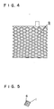
- Figure 4 is a top view of the grid cut out from the expanded sheet.
- Figure 5 is an enlarged sectional view of the skeletal part of the grid.
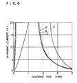
- Figure 6 is a graph illustrating the charging characteristics of an acid battery using the grid of the invention which has been left standing in a superdischarged state.
- a sheet bar of lead-calcium-tin alloy 1 was continuously formed into a ribbon by means of sheet bar caster 2 .
- the sheet bar had a thickness of 10 mm and a width of 80 mm.
- lead-calcium-tin alloys containing 0.03 - 0.15% by weight of calcium and 0 - 1.5% by weight of tin are preferred.
- a lead-calcium-tin alloy composed of 0.07% by weight of calcium, 0.25% of tin and a residual quantity of lead was used.
- the sheet bar 1 had a temperature of about 150°C which was lower than the recrystallization temperature of the alloy.
- the surface of the rolled sheet was constituted of a thin layer of lead-tin alloy pressure-bonded onto the lead-calcium-tin alloy layer.
- the final thicknesses of the sheets were 2.5, 2.25, 2.0, 1.75, 1.5, 1.25, 1.0 and 0.7 mm.
- each of the sheets was subjected to an expanding process in the usual way to obtain a product shown in Figure 3 where the central area 7 was left unexpanded and the left and right areas were expanded into diamond-shaped networks 8 , after which the product was cut into predetermined size and shape to obtain a grid 9 shown in Figure 4.
- the section of skeletal part of this grid 9 was so constructed that a thin layer of lead-tin alloy 4 was pressure-bonded onto one side of lead-calcium-tin alloy layer 1 .
- the lead-tin layer 4 was inclined toward the inner side of grid mesh due to the twisting force arising at the time of expanding processing.
- This expanded grid was used as a positive electrode, and a pasty active material was filled thereinto in the usual way.
- three lots of automobile lead acid batteries A, B and C were obtained.
- a usual battery D was also prepared by repeating the above-mentioned procedure except that the pressure-bonding treatment using lead-tin alloy sheet was not carried out. All these batteries had a form of 12V - 55D23.
- the batteries A - D were connected to a 12 ⁇ resistor and left standing for one week, after which they were left standing in open circuit for one week. Thereafter, they were charged at a constant voltage of 15V, and the change in current was followed. As the result, the comparative sample D necessitated one hour until it had reached the maximum current, while the samples using the grid of the invention reached the maximum current in only 5 minutes, demonstrating that the recovery characteristics after standing in super-discharged state was improved.
- Figure 6 illustrates one of the results.
- a grid is formed by an expanding processing of a sheet-formed elementary material prepared by integrating a sheet bar of lead-calcium-tin alloy with a lead-tin alloy sheet by cold rolling as has been mentioned above, the smallness of the tendency of self-discharge or the maintenance-free characteristics of the alloy sheet bar can be sufficiently utilized, and at the same time the formation of high-resistance passive state material at the interface between the grid and the pasty active material filled therein can also be prevented. As has been mentioned above, this can be achieved by enhancing the concentration (content) of tin in the surface layer of grid to 1.5% or more.
- the tin content in the sheet or foil of lead-tin alloy must be in the range of 1.5% to 30%.
- the alloy sheet bar By keeping the alloy sheet bar at a temperature of 130°C to 180°C at the time of cold rolling, the alloy can be prevented from recrystallization or the formation of coarse crystal particles of the alloy. Further, by adjusting the thickness of rolled lead-tin alloy sheet or foil to 0.7 mm or less and by carrying out the rolling to such an extent that thickness of the rolled sheet becomes 1/5 time or less the thickness before rolling, the bonding strength can be enhanced. Further, when the above-mentioned conditions are fulfilled, the rolled sheet exhibits a time-hardening effect if left standing for a necessary period of time after rolling, which enhances the tensile strength of the sheet.
- diamond-shaped network produced by expanding processing is desirable from the view point of material yield.
- a shape of punched sheet produced by punching out many holes of predetermined shape from a sheet (punching processing) is also usable.
- the same alloy as above composed of 0.07% calcium, 0.25% tin and a residual quantity of lead and having a thickness of 10 mm and a width of 80 mm was used.
- the lead-antinony alloy sheet was a ribbon-like sheet of lead-antinony alloy having a thickness of 0.3 mm and a width of 20 mm.
- the antimony content was 1.0% by weight.
- the final sheet obtained by cold rolling had a lessened tendency of self-discharge storage owing to the characteristics of the sheet bar alloy itself and, in addition, it had an increased mechanical strength owing to the use of the lead antimony sheet. Further, it prevented the formation of passive state material at the interface between the pasty active material and grid surface.
- the antimony content in the lead-antimony alloy sheet it is preferable to adjust the antimony content in the lead-antimony alloy sheet to 0.5 - 5% by weight. If the antimony content is lower than 0.5%, the addition of antimony cannot bring about a sufficient increase in mechanical strength and a sufficient prevention of the formation of passive state material at the interface between grid and active material. If the antimony content is higher than 5%, the product becomes poor in ductility and malleability even though mechanical strength can be enhanced. Thus, the lead-antimony alloy cannot exhibit an elongation enough to follow that of sheet bar when it is subjected to an integrating treatment together with sheet bar by the rolling, and there occur cracks and insufficient bonding.
- a sheet or a foil of lead-silver alloy is superposed on sheet bar and pressure-bonded by rolling.
- the same sheet bar as above was used.
- As the lead-silver alloy sheet a sheet having a thickness of 0.3 mm and containing 0.1% by weight of silver was used.
- the width of the sheet and the procedure for superposing it on sheet bar were the same as above, and the whole was subjected to rolling treatment.
- the lead-silver alloy sheet brought about good ductility and malleability, prevented the formation of passive state material at the interface between sheet surface and active material and improved the corrosion resistance.
- sheet bar in cooperation with the ability of sheet bar to prevent the self-discharge during storage, it can improve the chargeability after standing in a superdischarged state.
- the content of silver in the lead-silver alloy is 0.01 - 0.5%. If it is smaller than 0.01%, the resulting sheet cannot have sufficient corrosion resistance, ductility and malleability and the prevention of the formation of passive state material is insufficient. If the silver content is higher than 0.5%, the alloy is too high in cost. Further, such an alloy sheet has too high ductility and malleability even though corrosion resistance and preventive effect on the formation of passive state material are improved. Thus, when such a lead-silver sheet is integrated with sheet bar by rolling, the sheet slips on the surface of sheet bar so that no good pressure bonding can be achieved.
- the present invention can easily provide a grid for lead acid batteries excellent in the recovery characteristics after standing in a superdischarged state.
- the surface treatment necessary for improving the recovery characteristics can be applied to a limited necessary part, which enables to produce a lattice material without material loss.
Landscapes
- Chemical & Material Sciences (AREA)
- Chemical Kinetics & Catalysis (AREA)
- Electrochemistry (AREA)
- General Chemical & Material Sciences (AREA)
- Engineering & Computer Science (AREA)
- Materials Engineering (AREA)
- Cell Electrode Carriers And Collectors (AREA)
Abstract
Description
- The present invention relates to a lead acid batteries for use in electric source for automobiles and other fields, and more particularly to a process for producing a grid for use in lead acid batteries.
- Currently, there is an increasing tendency to use a lead-calcium alloy as the grid for lead acid batteries because of its excellent characteristic properties, i.e. the small loss in electrolytic solution after assemblage of battery and the slight self-discharge during storage.
- As compared with the lead-antimony alloy which has been used prior to lead-calcium alloy, however, lead-calcium alloy is inferior in castability and mechanical strength after casting. For these reasons, it has hitherto been conventional to form a lead-calcium alloy into a grid by rolling its ingot into a sheet and then subjecting the sheet to an expanding treatment.
- When an acid battery using such a grid of lead-calcium alloy is left standing for a long period of time in a discharged state, a high resistance substance is formed at the interface between the positive electrode and the active material and this high resistance substance makes the next charging procedure impossible.
- The first object of the present invention is to provide a process for producing a grid for use in lead acid batteries with which the above-mentioned problem can be solved.
- The second object of the present invention is to obtain a grid for use in lead acid batteries by a process which comprises superposing a sheet or a foil of a lead alloy on a sheet bar of a lead-calcium alloy, said lead alloy sheet or foil having a composition different from that of said sheet bar and having a thickness smaller than that of said sheet bar, followed by subjecting the superposed materials to a cold rolling to form an elementary sheet in which both the materials are integrated and then subjecting the elementary sheet to an expanding or punching process.
- The third object of the present invention is to provide a grid for use in lead acid batteries which is easy to produce and low in cost.
- Other objects of the present invention will become apparent from the examples of the invention mentioned later.
- According to the present invention, a grid is formed by superposing a sheet or a foil of a lead alloy on a sheet bar of a lead-calcium alloy, said sheet or foil having a composition different from that of said sheet bar and having a thickness different from that of said sheet bar, followed by subjecting the superposed materials to a cold rolling to integrate both the materials and to produce an elementary sheet having a thickness smaller than that of said sheet bar and then subjecting the elementary sheet thus obtained to a expanding process or a punching process.
- In the process of the invention, a grid is produced from a plate or a sheet of which superficial tin concentration has been enhanced by the above-mentioned cladding process by cold rolling as an elementary material, by which the formation of high resistance substance at the interface between the grid, made therefrom, and the active material can be prevented.
- It has been found that the formation of the high resistance substance at the interface between the positive electrode grid and the active material filled therein can effectively be prevented by adjusting the quantity (content) of tin in the lead-calcium alloy to 1.5% by weight (hereinafter, simply referred to as "%"). However, tin is more expensive than lead as an elementary material, so that it is undesirable from the viewpoint of industrial mass production to add as large an amount as 1.5% or more of tin into the grid alloy because it makes the over-all cost of the grid alloy too high.
- Thus, there have hitherto been devised various means for enhancing the concentration (content) of tin only in the interfacial part of grid making contact with active material. According to the present invention, a lead alloy sheet having a high tin content in its superficial part is produced by the so-called cladding process which comprises superposing a lead-tin alloy having a smaller thickness than that of sheet bar on a sheet bar of lead-calcium alloy and subjecting the superposed materials to a cold rolling. Generally saying, cladding process is effective for achieving a high bonding strength if combined with a heat treatment such as hot rolling process. The present inventors also found that hot rolling process which comprises heating a sheet bar of lead alloy to a temperature higher than its recrystallization temperature, superposing a lead-tin alloy on the heated sheet bar and rolling the superposed materials is effective for enhancing the bonding strength between the two layers. However, there is a tendency that, according to this method, the lead sheet cannot exhibit a sufficient time-hardening effect so that tensile strength becomes low. In view of above, the present inventors have studied the optimum conditions of cladding on the premise that a sheet bar of lead alloy is subjected to cold rolling at a temperature not higher than the recrystallization temperature of the alloy. As the result, it has been found that a clad sheet having a bonding strength enough to endure the expanding process can be produced by making the thickness of the lead-tin alloy superposed on the sheet bar as small as 0.7 mm or less and adjusting the rolling ratio (the ratio of thickness of elementary material before rolling to the thickness of rolled sheet) to a value of 5 or more. According to this process, a high strength of sheet and a high bonding strength at the bonded surface can both be achieved simultaneously. Further, its procedure is so simple that a mere pressure bonding of different metals is enough for the purpose. Further the clad material has a high dimensional accuracy regarding thickness, and the process is accompanied with no material loss. The expanded grid obtained by this process has a predetermined thickness of a tin-rich layer containing a predetermined concentration of tin on its surface.
- Figure 1 is an schematic illustration of the process for producing the ribbon-like sheet-formed elementary material used for the production of the grid of the invention. Figure 2 is an enlarged sectional view of said sheet-formed elementary material. Figure 3 is a top view of the sheet-formed material having been subjected to expanding process. Figure 4 is a top view of the grid cut out from the expanded sheet. Figure 5 is an enlarged sectional view of the skeletal part of the grid. Figure 6 is a graph illustrating the charging characteristics of an acid battery using the grid of the invention which has been left standing in a superdischarged state.
- Hereunder, examples of the invention will be mentioned.
- As shown in Figure 1, a sheet bar of lead-calcium-tin alloy 1 was continuously formed into a ribbon by means of
sheet bar caster 2. The sheet bar had a thickness of 10 mm and a width of 80 mm. As for the composition, lead-calcium-tin alloys containing 0.03 - 0.15% by weight of calcium and 0 - 1.5% by weight of tin are preferred. In the present experiment, a lead-calcium-tin alloy composed of 0.07% by weight of calcium, 0.25% of tin and a residual quantity of lead was used. At the outlet ofsheet bar caster 2, the sheet bar 1 had a temperature of about 150°C which was lower than the recrystallization temperature of the alloy. One surface of the ribbon-like sheet bar 1 was briefly ground withbuff 3. Then, two sheets per one run of lead-tin alloy 4, having a thickness of 1.2, 1.0, 0.7, 0.5, 0.3 or 0.1 mm, having a width of 20 mm throughout all the runs and containing 5% by weight of tin throughout all the runs, were placed thereon in parallel with each other at an interval of 20 mm. Thereafter, the whole was passed through a continuous multi-stage rollingmill 5 equipped with three or more stages of rolls to prepare alead alloy sheet 6 having the same width of 80 mm. Figure 2 illustrates this rolled lead alloy sheet. The surface of the rolled sheet was constituted of a thin layer of lead-tin alloy pressure-bonded onto the lead-calcium-tin alloy layer. The final thicknesses of the sheets were 2.5, 2.25, 2.0, 1.75, 1.5, 1.25, 1.0 and 0.7 mm. - Each of the lead alloy sheets thus obtained was bent so that the lead-tin alloy came outside, and the state of peeling was investigated. The results were as shown in Table 1. In the runs where the thickness of lead-tin alloy sheet was 0.7 mm or less and rolling ratio was 5 or more, a good lead alloy sheet allowing no peeling of the lead-tin alloy sheet from sheet bar was obtained.

Δ : Somewhat good
X : Not good - Then, each of the sheets was subjected to an expanding process in the usual way to obtain a product shown in Figure 3 where the
central area 7 was left unexpanded and the left and right areas were expanded into diamond-shaped networks 8, after which the product was cut into predetermined size and shape to obtain a grid 9 shown in Figure 4. As shown in the enlarged view of Figure 5, the section of skeletal part of this grid 9 was so constructed that a thin layer of lead-tin alloy 4 was pressure-bonded onto one side of lead-calcium-tin alloy layer 1. The lead-tin layer 4 was inclined toward the inner side of grid mesh due to the twisting force arising at the time of expanding processing. - This expanded grid was used as a positive electrode, and a pasty active material was filled thereinto in the usual way. Thus, three lots of automobile lead acid batteries A, B and C were obtained. Further, for comparison, a usual battery D was also prepared by repeating the above-mentioned procedure except that the pressure-bonding treatment using lead-tin alloy sheet was not carried out. All these batteries had a form of 12V - 55D23.
- The batteries A - D were connected to a 12 Ω resistor and left standing for one week, after which they were left standing in open circuit for one week. Thereafter, they were charged at a constant voltage of 15V, and the change in current was followed. As the result, the comparative sample D necessitated one hour until it had reached the maximum current, while the samples using the grid of the invention reached the maximum current in only 5 minutes, demonstrating that the recovery characteristics after standing in super-discharged state was improved. Figure 6 illustrates one of the results.
- In the example presented above, only one surface of sheet bar made of lead-calcium-tin alloy was subjected to cladding treatment using a lead-tin alloy sheet by cold rolling. Apart from such an embodiment, it is also possible, of course, to subject both surfaces of sheet bar to cladding treatment using a sheet or a foil of lead-tin alloy.
- If a grid is formed by an expanding processing of a sheet-formed elementary material prepared by integrating a sheet bar of lead-calcium-tin alloy with a lead-tin alloy sheet by cold rolling as has been mentioned above, the smallness of the tendency of self-discharge or the maintenance-free characteristics of the alloy sheet bar can be sufficiently utilized, and at the same time the formation of high-resistance passive state material at the interface between the grid and the pasty active material filled therein can also be prevented. As has been mentioned above, this can be achieved by enhancing the concentration (content) of tin in the surface layer of grid to 1.5% or more. The tin content in the sheet or foil of lead-tin alloy must be in the range of 1.5% to 30%. With increasing content of tin, the cost of the sheet or foil rises. In addition, with increasing content of tin, the lead-tin alloy becomes softer, which disturbs the bonding to sheet bar at the time of cold rolling. This can cause a decrease in capacity when such a grid is set into a lead acid battery.
- By keeping the alloy sheet bar at a temperature of 130°C to 180°C at the time of cold rolling, the alloy can be prevented from recrystallization or the formation of coarse crystal particles of the alloy. Further, by adjusting the thickness of rolled lead-tin alloy sheet or foil to 0.7 mm or less and by carrying out the rolling to such an extent that thickness of the rolled sheet becomes 1/5 time or less the thickness before rolling, the bonding strength can be enhanced. Further, when the above-mentioned conditions are fulfilled, the rolled sheet exhibits a time-hardening effect if left standing for a necessary period of time after rolling, which enhances the tensile strength of the sheet.
- As for the shape of grid, diamond-shaped network produced by expanding processing is desirable from the view point of material yield. However, a shape of punched sheet produced by punching out many holes of predetermined shape from a sheet (punching processing) is also usable.
- Next, as another example, there will be mentioned a case that a lead-antimony alloy having a smaller thickness than sheet bar and different in composition from sheet bar is roll-bonded onto a sheet bar of lead-calcium-tin alloy.
- As the sheet bar, the same alloy as above composed of 0.07% calcium, 0.25% tin and a residual quantity of lead and having a thickness of 10 mm and a width of 80 mm was used. On the other hand, the lead-antinony alloy sheet was a ribbon-like sheet of lead-antinony alloy having a thickness of 0.3 mm and a width of 20 mm. The antimony content was 1.0% by weight.
- Two lead-antimony alloy sheets were placed on the sheet bar in parallel with each other at an interval of 20 mm, and the whole was subjected to a cold rolling process in the same manner as above. The final sheet obtained by cold rolling had a lessened tendency of self-discharge storage owing to the characteristics of the sheet bar alloy itself and, in addition, it had an increased mechanical strength owing to the use of the lead antimony sheet. Further, it prevented the formation of passive state material at the interface between the pasty active material and grid surface.
- According to the study of the present inventors, it is preferable to adjust the antimony content in the lead-antimony alloy sheet to 0.5 - 5% by weight. If the antimony content is lower than 0.5%, the addition of antimony cannot bring about a sufficient increase in mechanical strength and a sufficient prevention of the formation of passive state material at the interface between grid and active material. If the antimony content is higher than 5%, the product becomes poor in ductility and malleability even though mechanical strength can be enhanced. Thus, the lead-antimony alloy cannot exhibit an elongation enough to follow that of sheet bar when it is subjected to an integrating treatment together with sheet bar by the rolling, and there occur cracks and insufficient bonding.
- In yet another example, a sheet or a foil of lead-silver alloy is superposed on sheet bar and pressure-bonded by rolling.
- The same sheet bar as above was used. As the lead-silver alloy sheet, a sheet having a thickness of 0.3 mm and containing 0.1% by weight of silver was used. The width of the sheet and the procedure for superposing it on sheet bar were the same as above, and the whole was subjected to rolling treatment.
- The results were as follows. Thus, owing to the presence of silver, the lead-silver alloy sheet brought about good ductility and malleability, prevented the formation of passive state material at the interface between sheet surface and active material and improved the corrosion resistance. Thus, in cooperation with the ability of sheet bar to prevent the self-discharge during storage, it can improve the chargeability after standing in a superdischarged state.
- Preferably, the content of silver in the lead-silver alloy is 0.01 - 0.5%. If it is smaller than 0.01%, the resulting sheet cannot have sufficient corrosion resistance, ductility and malleability and the prevention of the formation of passive state material is insufficient. If the silver content is higher than 0.5%, the alloy is too high in cost. Further, such an alloy sheet has too high ductility and malleability even though corrosion resistance and preventive effect on the formation of passive state material are improved. Thus, when such a lead-silver sheet is integrated with sheet bar by rolling, the sheet slips on the surface of sheet bar so that no good pressure bonding can be achieved.
- As above, the present invention can easily provide a grid for lead acid batteries excellent in the recovery characteristics after standing in a superdischarged state.
- Additionally saying, according to the invention, the surface treatment necessary for improving the recovery characteristics can be applied to a limited necessary part, which enables to produce a lattice material without material loss.
Claims (13)
Priority Applications (3)
| Application Number | Priority Date | Filing Date | Title |
|---|---|---|---|
| JP59245062A JPS61124064A (en) | 1984-11-20 | 1984-11-20 | Grid body for lead storage battery and its manufacture |
| DE8686304330T DE3686768T2 (en) | 1986-06-06 | 1986-06-06 | METHOD FOR PRODUCING A GRID FOR LEAD ACCUMULATORS. |
| EP86304330A EP0252189B1 (en) | 1986-06-06 | 1986-06-06 | Process for producing a grid for use in lead acid batteries |
Applications Claiming Priority (1)
| Application Number | Priority Date | Filing Date | Title |
|---|---|---|---|
| EP86304330A EP0252189B1 (en) | 1986-06-06 | 1986-06-06 | Process for producing a grid for use in lead acid batteries |
Publications (3)
| Publication Number | Publication Date |
|---|---|
| EP0252189A2 true EP0252189A2 (en) | 1988-01-13 |
| EP0252189A3 EP0252189A3 (en) | 1988-10-12 |
| EP0252189B1 EP0252189B1 (en) | 1992-09-16 |
Family
ID=8196036
Family Applications (1)
| Application Number | Title | Priority Date | Filing Date |
|---|---|---|---|
| EP86304330A Expired - Lifetime EP0252189B1 (en) | 1984-11-20 | 1986-06-06 | Process for producing a grid for use in lead acid batteries |
Country Status (3)
| Country | Link |
|---|---|
| EP (1) | EP0252189B1 (en) |
| JP (1) | JPS61124064A (en) |
| DE (1) | DE3686768T2 (en) |
Cited By (6)
| Publication number | Priority date | Publication date | Assignee | Title |
|---|---|---|---|---|
| FR2668652A1 (en) * | 1990-10-31 | 1992-04-30 | Magneti Marelli Spa Ind | METHOD FOR MANUFACTURING A GRID FOR LEAD - ACID BATTERY ELECTRODES. |
| EP0504815A1 (en) * | 1991-03-18 | 1992-09-23 | Matsushita Electric Industrial Co., Ltd. | Sealed lead-acid secondary battery |
| EP0655792A1 (en) * | 1993-10-29 | 1995-05-31 | Gnb Battery Technologies Inc. | Battery grids and plates and lead-acid batteries made thereof |
| EP0902491A1 (en) * | 1997-09-09 | 1999-03-17 | Matsushita Electric Industrial Co., Ltd | Expanded grid for electrode plate of lead-acid battery |
| EP0926751A3 (en) * | 1997-12-18 | 1999-12-08 | Texas Instruments Incorporated | Method of making clad materials using lead alloys and composite strips made by such method |
| CN105917503A (en) * | 2013-10-15 | 2016-08-31 | 株式会社杰士汤浅国际 | Valve-regulated lead-acid battery |
Families Citing this family (3)
| Publication number | Priority date | Publication date | Assignee | Title |
|---|---|---|---|---|
| JPH01140557A (en) * | 1987-11-26 | 1989-06-01 | Shin Kobe Electric Mach Co Ltd | Lead-acid battery |
| JP4972818B2 (en) * | 2000-10-30 | 2012-07-11 | 株式会社Gsユアサ | Method for manufacturing grid for lead-acid battery |
| JP4678117B2 (en) * | 2001-11-06 | 2011-04-27 | 株式会社Gsユアサ | Lead acid battery |
Family Cites Families (6)
| Publication number | Priority date | Publication date | Assignee | Title |
|---|---|---|---|---|
| JPS544329A (en) * | 1977-06-14 | 1979-01-13 | Furukawa Electric Co Ltd | Grating plate for lead storage battery and method of making same |
| JPS5480519A (en) * | 1977-12-09 | 1979-06-27 | Citizen Watch Co Ltd | Alkali cell |
| US4279977A (en) * | 1978-09-11 | 1981-07-21 | General Motors Corporation | Lead-calcium-tin battery grid |
| JPS5539141A (en) * | 1978-09-11 | 1980-03-18 | Yuasa Battery Co Ltd | Lead storage battery |
| JPS58169771A (en) * | 1982-03-30 | 1983-10-06 | Shin Kobe Electric Mach Co Ltd | Plate for lead storage battery |
| WO1986003343A1 (en) * | 1984-11-19 | 1986-06-05 | Revere Copper And Brass Incorporated | Laminated lead alloy strip for battery grid application and electrochemical cells utilizing same |
-
1984
- 1984-11-20 JP JP59245062A patent/JPS61124064A/en active Granted
-
1986
- 1986-06-06 DE DE8686304330T patent/DE3686768T2/en not_active Expired - Lifetime
- 1986-06-06 EP EP86304330A patent/EP0252189B1/en not_active Expired - Lifetime
Cited By (16)
| Publication number | Priority date | Publication date | Assignee | Title |
|---|---|---|---|---|
| GB2250856A (en) * | 1990-10-31 | 1992-06-17 | Magneti Marelli Spa | Producing composite grid for lead accumulator by casting |
| ES2036938A2 (en) * | 1990-10-31 | 1993-06-01 | Magneti Marelli Spa | Producing composite grid for lead accumulator by casting |
| GB2250856B (en) * | 1990-10-31 | 1995-01-25 | Magneti Marelli Spa | A method of producing a grid for lead-accumulator electrodes |
| FR2668652A1 (en) * | 1990-10-31 | 1992-04-30 | Magneti Marelli Spa Ind | METHOD FOR MANUFACTURING A GRID FOR LEAD - ACID BATTERY ELECTRODES. |
| EP0504815A1 (en) * | 1991-03-18 | 1992-09-23 | Matsushita Electric Industrial Co., Ltd. | Sealed lead-acid secondary battery |
| EP0655792A1 (en) * | 1993-10-29 | 1995-05-31 | Gnb Battery Technologies Inc. | Battery grids and plates and lead-acid batteries made thereof |
| AU680484B2 (en) * | 1993-10-29 | 1997-07-31 | Exide Technologies | Battery grids and plates and lead-acid batteries made using such grids and plates |
| US6037081A (en) * | 1997-09-09 | 2000-03-14 | Matsushita Electric Industrial Co., Ltd | Expanded grid for electrode plate of lead-acid battery |
| EP0902491A1 (en) * | 1997-09-09 | 1999-03-17 | Matsushita Electric Industrial Co., Ltd | Expanded grid for electrode plate of lead-acid battery |
| EP0926751A3 (en) * | 1997-12-18 | 1999-12-08 | Texas Instruments Incorporated | Method of making clad materials using lead alloys and composite strips made by such method |
| US6096145A (en) * | 1997-12-18 | 2000-08-01 | Texas Instruments Incorporated | Method of making clad materials using lead alloys and composite strips made by such method |
| US6475675B1 (en) | 1997-12-18 | 2002-11-05 | Engineered Materials Solutions, Inc. | Method of making clad materials using lead alloys and composite strips made by such method |
| CN105917503A (en) * | 2013-10-15 | 2016-08-31 | 株式会社杰士汤浅国际 | Valve-regulated lead-acid battery |
| EP3059791A4 (en) * | 2013-10-15 | 2017-06-21 | GS Yuasa International Ltd. | Valve-regulated lead-acid battery |
| US10084209B2 (en) | 2013-10-15 | 2018-09-25 | Gs Yuasa International Ltd. | Valve regulated lead-acid battery |
| CN105917503B (en) * | 2013-10-15 | 2019-03-29 | 株式会社杰士汤浅国际 | VRLA |
Also Published As
| Publication number | Publication date |
|---|---|
| JPS61124064A (en) | 1986-06-11 |
| JPH0481307B2 (en) | 1992-12-22 |
| EP0252189B1 (en) | 1992-09-16 |
| EP0252189A3 (en) | 1988-10-12 |
| DE3686768D1 (en) | 1992-10-22 |
| DE3686768T2 (en) | 1993-02-11 |
Similar Documents
| Publication | Publication Date | Title |
|---|---|---|
| US4805277A (en) | Process for producing a grid for use in lead acid batteries | |
| US4939051A (en) | Grid for use in lead acid batteries and process for producing same | |
| US4906540A (en) | Lead-acid battery having a grid base of a lead-calcium alloy and a layer of lead-antimony-stannum alloy roll-bonded to the grid base | |
| US3310438A (en) | Dispersion strengthened lead battery grids | |
| DE60203257T2 (en) | METHOD FOR PRODUCING AN ALLOYED LAYERED BATTERY GRILLE | |
| EP0213203B1 (en) | Grid for lead storage batteries and a method of producing the same | |
| US6037081A (en) | Expanded grid for electrode plate of lead-acid battery | |
| EP0252189B1 (en) | Process for producing a grid for use in lead acid batteries | |
| US6802917B1 (en) | Perforated current collectors for storage batteries and electrochemical cells, having improved resistance to corrosion | |
| JP3182856B2 (en) | Manufacturing method of electrode plate for lead-acid battery | |
| US4109358A (en) | Method for making storage battery grid from lead-tin-zinc alloy | |
| JPS62501318A (en) | Laminated lead alloy strip for storage battery grid and electrochemical battery using the same | |
| TWI328895B (en) | Method of producing grid for lead -acid battery and lead -acid battery | |
| JPH0326905B2 (en) | ||
| JPH09115524A (en) | Lead plate battery plate grid and method of manufacturing the same | |
| US4035556A (en) | Lead base alloy for use in a storage battery grid | |
| JPH10321236A (en) | Lead storage battery | |
| JPS61200670A (en) | Grid body for lead storage battery and manufacture thereof | |
| JPH0213425B2 (en) | ||
| Devitt et al. | Deep Discharge Cycle Life of Cells Constructed with Wrought Antimonial Lead Grids | |
| JPS60185365A (en) | Manufacture of substrate for storage battery plate | |
| JP2002100365A (en) | Rolled lead alloy sheet for storage battery and lead storage battery using it | |
| JPH05343070A (en) | Manufacture of lead alloy sheet for expanded grid body of lead acid battery | |
| JPS6321314B2 (en) | ||
| JPS6043907B2 (en) | Manufacturing method of high-strength lead alloy plate material with high ductility |
Legal Events
| Date | Code | Title | Description |
|---|---|---|---|
| PUAI | Public reference made under article 153(3) epc to a published international application that has entered the european phase |
Free format text: ORIGINAL CODE: 0009012 |
|
| AK | Designated contracting states |
Kind code of ref document: A2 Designated state(s): DE FR GB |
|
| PUAL | Search report despatched |
Free format text: ORIGINAL CODE: 0009013 |
|
| AK | Designated contracting states |
Kind code of ref document: A3 Designated state(s): DE FR GB |
|
| 17P | Request for examination filed |
Effective date: 19881208 |
|
| 17Q | First examination report despatched |
Effective date: 19900830 |
|
| GRAA | (expected) grant |
Free format text: ORIGINAL CODE: 0009210 |
|
| AK | Designated contracting states |
Kind code of ref document: B1 Designated state(s): DE FR GB |
|
| REF | Corresponds to: |
Ref document number: 3686768 Country of ref document: DE Date of ref document: 19921022 |
|
| ET | Fr: translation filed | ||
| PLBE | No opposition filed within time limit |
Free format text: ORIGINAL CODE: 0009261 |
|
| STAA | Information on the status of an ep patent application or granted ep patent |
Free format text: STATUS: NO OPPOSITION FILED WITHIN TIME LIMIT |
|
| 26N | No opposition filed | ||
| REG | Reference to a national code |
Ref country code: GB Ref legal event code: 746 Effective date: 19960628 |
|
| REG | Reference to a national code |
Ref country code: GB Ref legal event code: IF02 |
|
| REG | Reference to a national code |
Ref country code: FR Ref legal event code: D6 |
|
| PGFP | Annual fee paid to national office [announced via postgrant information from national office to epo] |
Ref country code: GB Payment date: 20050601 Year of fee payment: 20 |
|
| PGFP | Annual fee paid to national office [announced via postgrant information from national office to epo] |
Ref country code: DE Payment date: 20050602 Year of fee payment: 20 |
|
| PGFP | Annual fee paid to national office [announced via postgrant information from national office to epo] |
Ref country code: FR Payment date: 20050608 Year of fee payment: 20 |
|
| REG | Reference to a national code |
Ref country code: GB Ref legal event code: PE20 |
|
| PG25 | Lapsed in a contracting state [announced via postgrant information from national office to epo] |
Ref country code: GB Free format text: LAPSE BECAUSE OF EXPIRATION OF PROTECTION Effective date: 20060605 |