EP0251084A2 - Heizvorrichtung, insbesondere für Schischuhe - Google Patents
Heizvorrichtung, insbesondere für Schischuhe Download PDFInfo
- Publication number
- EP0251084A2 EP0251084A2 EP87108850A EP87108850A EP0251084A2 EP 0251084 A2 EP0251084 A2 EP 0251084A2 EP 87108850 A EP87108850 A EP 87108850A EP 87108850 A EP87108850 A EP 87108850A EP 0251084 A2 EP0251084 A2 EP 0251084A2
- Authority
- EP
- European Patent Office
- Prior art keywords
- circuit
- box
- battery
- boot
- seat
- Prior art date
- Legal status (The legal status is an assumption and is not a legal conclusion. Google has not performed a legal analysis and makes no representation as to the accuracy of the status listed.)
- Withdrawn
Links
Images


Classifications
-
- A—HUMAN NECESSITIES
- A43—FOOTWEAR
- A43B—CHARACTERISTIC FEATURES OF FOOTWEAR; PARTS OF FOOTWEAR
- A43B3/00—Footwear characterised by the shape or the use
- A43B3/34—Footwear characterised by the shape or the use with electrical or electronic arrangements
- A43B3/35—Footwear characterised by the shape or the use with electrical or electronic arrangements with electric heating arrangements
-
- A—HUMAN NECESSITIES
- A43—FOOTWEAR
- A43B—CHARACTERISTIC FEATURES OF FOOTWEAR; PARTS OF FOOTWEAR
- A43B3/00—Footwear characterised by the shape or the use
- A43B3/34—Footwear characterised by the shape or the use with electrical or electronic arrangements
Definitions
- the present invention relates to a heating device, particularly for ski boots.
- Boots including such known devices comprise an inner boot which comprises an electric resistance heater connected to one or more rechargeable electric batteries.
- Such batteries are electrically connected to a socket for permitting their recharging, which socket is accessible on the boot, the supply of power to the resistance heater being allowed by operating a suitable switch.
- the main disadvantage found in such known devices resides in the fact that the ski boot must be placed proximate to an external electric power supply, and that the user must use a battery charger in order to restore the functionality of the batteries.
- the main aim of the present invention is therefore to eliminate all of the disadvantages of known types of heating devices for ski boots.
- an object of the invention is to provide a heating device which has means for supplying power to an electric resistor circuit contained within a ski boot and which allows direct recharging of the power which can be restored therein without requiring any external accessories and without the need to place said boot proximate to a power source.
- a further important object of the invention is to provide a heating device which associates the above described characteristic with that of allowing said recharging in conditions of absolute safety for the user.
- Another important object of the invention is to provide a device which furthermore allows its quick and easy replacement in case of maintainance, allowing at the same time the user to make use of the ski boots, even during recharging.
- Another object of the invention is to devise a heating device with small dimensions and which is absolutely safe and reliable while skiing.
- Still another object of the invention is to provide a heating device which allows an optimum supply of powr to the electric resistance heating circuit within the ski boot, without requiring the user to perform said function by continuous and constant use of a switch interposed between said device and said circuit.
- Not least object is to obtain a device which automatically prevents any damage to the batterry avoiding possible overcharging or excessive discharging thereof.
- a heating device particularly for ski boots comprising an electrical resistance heating circuit, characterized in that it comprises, in combination, at least one battery, a substantially watertight box-like structure, battery charging means, at least one first circuit adapted for preventing overcharging of said battery, at least one second circuit adapted for preventing excessive discharging of said battery, and at least one third circuit adapted for controlling power fed to said electrical resistance heating circuit, said substantially watertight box-like structure being removably associable with a ski boot, connectable to said electric resistance heating circuit, and adapted for containing said battery, said first circuit, said second circuit, and said third circuit.
- the heating device 1 particularly for ski boots 2, comprises a battery charger 3 of the switching type, which allows recharging with voltage values ranging from 12 to 24 volts DC, and from 100 to 240 volts AC with automatic voltage level compensation.
- Said battery charger 3 comprises an automatic charge-cut off circuit 4 adapted to prevent overcharging of the battery and controlled by the charging time and/or the battery temperature, so as to stop charging when the charging time and/or the battery temperature exceed preset values.
- This battery charger 3 may be of any type suitable for alllowing recharging of the battery through connection to an external, AC or DC, power supply; for example it may be the same as the battery charger incorporated in the shaver HP 1335 manufactured by Philips Shave.
- the batteries, indicated at 5, are electrically connected, through line 40, to the battery charger 3 and, through line 41, to an automatic switch circuit 6 intended to cut off feeding of the heating resistor circuit 8 and thus to stop discharge of the batteries when the voltage across the batteries 5 falls below the present value, said automatic switch circuit allowing protection of the batteries, by preventing excessive discharge thereof.
- the heating device 1 furthermore comprises a control circuit 7 for regulating the power fed to the resistor heating circuit 8 arrnged in the ski boot 2.
- control circuit 7 The function of this control circuit 7 is thus to adjust the temperature within the ski boot according to the requirements of the user.
- control circuit 7 is of the non-dissipating type, so as to allow the user, besides the adjustment of the temperature within the ski boot, also to increase the life of the batteries 5.
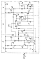
- circuits 6 and 7 An illustrative embodiment of circuits 6 and 7 is shown in Fig. 3a, wherein section A corresponds to the automatic switch circuit 6 and sections B and C form the control circuit 7.
- section A fed on line 41, comprises a first transistor 45 which, biased by resistors 46-49, sets the operation threshold of the device.
- First transistor 45 drives, through resistors 50, 51, second transistor 52 which, during normal operation, is in the ON state and drives sections B and C. In this state, LED 53 is switched on.
- transistor 52 is switched off, thereby switching off sections B and C so as to stop feeding of the heater circuit 8.
- Resistor 49 of the NTC type is intended to thermally compensate transistor 45.
- Section B defines the power regulation portion and includes a differential amplifier circuit driven by transistor 52 through transistor 59 and comprising transistors 54 and 55 and components 56-58 forming with the latter a self-exciter structure. Regulation of the duty cycle of this structure is obtained through potentiometer 60 which allows selection of the reference voltage of the differential amplifier circuit. The variable-width pulse fed by transistor 55 are then supplied, though resistor 61, to the base of transistor 62 of section C. Potentiometer 60 is furthermore mechanically coupled to switch 70 arranged on line 41 to interrupt current flow.
- This section C defines the final power section and includes a first, gain portion formed by transistors 62 and 63, and a second, power section formed by transistor 64 connected with its collector electrode to line 65 leading to the heating circuit 8.
- Resistor 66 of the NTC type, is connected between the base and emitter of transistor 64 and is intended to protect the latter against short-circuits by limiting the base current.
- control circuit 7 supplying power as selected until the voltage fed by the batteries falls below the set threshold and automatic switch ciruit 6 causes switching off of control circuit 7 and therefore the resistor heating circuit 8.
- the battery charger 3, the batteries 5, the circuits 4, 6 and 7 are all enclosed within a watertight box-like structure 11 carrying the control knob 12 for the potentiometer 60 and pins 13, in electrical contact with line 65, for connection to the heating circuit 8.
- the box-like structure 11 further carries a lamp 14 connected to the battery charger 3 and the LED 53 forming part, as already explained, of control circuit 7 for verifying the charge and the discharge of the batteries.
- pins 13 may be used also to connect the device to an external recharging power supply, but further electrical connection elements may be instead provided for this purpose.
- the box-like structure 11 has the shape of a parallelepipedon with external projections or ribs 15 adapted to facilitate gripping by the user.
- the box-like structure 11 can be removably associated with ski boots 2, for example at a suitable flat seat 16 provided on the front quarter 17 of the boot and provided with a pair of sockets 18 for the pins 13 adapted to allow the electrical coupling thereof to the circuit 8.
- Fig. 5 illustrates a ski boot wich is provided, at the rear quarter 19, with a container 20 having a laterallyopening seat 21, configured so as to removably insert the box-like structure 11, also in this case there being provided, inside said seat, suitable sockets for the connection to the circuit 8 of the device 1.
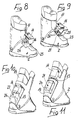
- Fig. 6 instead illustrates a ski boot 2 having the front quarter 17 with a seat 21 upwardly open and configured so as to removably accommodate and surround the box-like structure 11 so as to protect it from possible shocks during skiing.
- control knob 12 for the potentiometer as well as the control lights 14 and 53, are positioned so as to be visible and accessible by the user.
- Fig. 7 illustrates a ski boot 2, having the container 20 at a rear portion of the quarter 19, in said embodiment the seat 21 opening towards the interior of the boot 2.
- a recess is thus defined which is adapted to allow the removable insertion of the box-like structure 11, within said seat 21 there protruding preset terminals 22 adapted to allow electrical connection to the pins 13.
- Fig. 8 illustrates a ski boot 2, on the upper region of the shell 23 thereof adjacent to the front quarter 17 there being provided a seat 16 on which is removably placed a box-like structure 11 provided with sockets for the connection to the heating circuit 8, shaped complementarily with respect to preset pins 24 provided and projecting from said seat 16.
- Fig. 9 illustrates a ski boot 2, on the upper region of the shell 23 whereof, adjacent to the front quarter 17, is provided, instead, a seat 21 adapted to accommodate the box-like structure 11, the same being protected within said seat, which can be closed by means of a suitable closure 25.
- suitable pins 24 for the connection to the device 1 of the heating circuit 8 project from said seat 21.
- Fig. 10 illustrates a ski boot 2, on the rear quarter 19 of which is provided and projects a projection 26 provided with a flat surface 27 facing towards the top of the boot 2, with which the box-like structure 11 is rmovably associable, by means of the pins 13, said protrusion 26 being provided with suitable sockets for the pins 13 so as to allow electical connection of the device 1 to the circuit 8 within the boot.
- Fig. 11 instead illustrates a ski boot 2, provided, at the rear quarter 19, with a container 20, provided with a seat 21 arranged therein and configured so as to removably accommodate the box-like structure 11.
- Said seat is provided with an opening towards the upper end of the quarter 19.
- a heating device having been provided which is associable with the ski boot, which can be removed therefrom and placed directly at a power source, said device allowing the recharging of the batteries inserted therein without the need of an external battery charger.
- the user may, for example, recharge the batteries by electrically connecting the box-like structure 11 to the battery of the car while travelling towards the skiing resorts.
- the insertion of the device within a watertight box-like structure prevents any malfunction due to possible water infiltrations while skiing.
- the user can send the entire box-like structue 11 to be repaired, which in any case will still allow the boot to be used even with the box-like structure 11 removed therefrom.
- the presence within the device of a circuit for regulation and power supply furthermore allows the user to achieve an optimum heating condition within the ski boot, it being possible to achieve said condition by reducing the current on the load.
- the presence of the automatic cut off and control circuits allows to keep the batteries always efficient even if the user fails to notice an excessively long use thereof or an excessively longlasting connection thereof to a power source.
- the materials and the dimensions of the individual components, as well as the components of the individual circuits which compose the heating device may be any according to specific requirements.
Landscapes
- Engineering & Computer Science (AREA)
- Microelectronics & Electronic Packaging (AREA)
- Footwear And Its Accessory, Manufacturing Method And Apparatuses (AREA)
Applications Claiming Priority (2)
| Application Number | Priority Date | Filing Date | Title |
|---|---|---|---|
| IT8659390U IT209335Z2 (it) | 1986-06-30 | 1986-06-30 | Dispositivo di riscaldamento, particolarmente per scarpe da sci. |
| IT5939086U | 1986-06-30 |
Publications (2)
| Publication Number | Publication Date |
|---|---|
| EP0251084A2 true EP0251084A2 (de) | 1988-01-07 |
| EP0251084A3 EP0251084A3 (de) | 1989-10-25 |
Family
ID=11289352
Family Applications (1)
| Application Number | Title | Priority Date | Filing Date |
|---|---|---|---|
| EP87108850A Withdrawn EP0251084A3 (de) | 1986-06-30 | 1987-06-20 | Heizvorrichtung, insbesondere für Schischuhe |
Country Status (4)
| Country | Link |
|---|---|
| US (1) | US4780968A (de) |
| EP (1) | EP0251084A3 (de) |
| JP (1) | JPS6324901A (de) |
| IT (1) | IT209335Z2 (de) |
Cited By (8)
| Publication number | Priority date | Publication date | Assignee | Title |
|---|---|---|---|---|
| WO1993014657A1 (de) * | 1992-01-24 | 1993-08-05 | Rolf Biedert | Heizvorrichtung für schuhe, insbesondere skistiefel |
| GB2284533A (en) * | 1993-12-10 | 1995-06-14 | Great Interntional Footwear Li | Heated footwear |
| WO2013101920A1 (en) * | 2011-12-30 | 2013-07-04 | The Schawbel Corporation | Heated insoles |
| US9314064B2 (en) | 2013-12-04 | 2016-04-19 | Schawbel Technologies Llc | Heated insole with removable heating assembly |
| USD772546S1 (en) | 2014-04-09 | 2016-11-29 | Schawbel Technologies Llc | Insole |
| US9538807B2 (en) | 2013-12-04 | 2017-01-10 | Schawbel Technologies Llc | Assembly for inclusion in a heated insole |
| US9572397B2 (en) | 2013-12-04 | 2017-02-21 | Schawbel Technologies Llc | Heated insole with removable assembly |
| USD794813S1 (en) | 2015-07-15 | 2017-08-15 | Schawbel Technologies Llc | Heat pack |
Families Citing this family (28)
| Publication number | Priority date | Publication date | Assignee | Title |
|---|---|---|---|---|
| IT8522141V0 (it) * | 1985-06-11 | 1985-06-11 | Nordica Spa | Struttura di calzatura incorporante un dispositivo di riscaldamento, particolarmente per scarponi da sci. |
| FR2636541B1 (fr) * | 1988-09-19 | 1991-03-29 | Salomon Sa | Chaussure de ski alpin ou de randonnee pourvue d'un dispositif de chauffage |
| US5086573A (en) * | 1988-09-19 | 1992-02-11 | Salomon S.A. | Wearing apparel having an energy consuming device |
| US5033213A (en) * | 1988-09-19 | 1991-07-23 | Salomon S.A. | Wearing apparel having an energy consuming device |
| US5075983A (en) * | 1988-09-19 | 1991-12-31 | Salomon S. A. | Wearing apparel having energy consuming device |
| US4950868A (en) * | 1989-03-03 | 1990-08-21 | Marmon Holdings, Inc. | Heated gloves |
| US4950858A (en) * | 1989-04-25 | 1990-08-21 | Stephen Slenker | Boot heater |
| US5041717A (en) * | 1989-10-10 | 1991-08-20 | Alpine International Corporation | Universal ski boot heater |
| US5063690A (en) * | 1990-01-17 | 1991-11-12 | Stephen Slenker | Shoe or boot heater with shoelace mounted power source |
| US5033212A (en) * | 1990-10-09 | 1991-07-23 | Evanyk Walter R | System for increasing the visibility of an object |
| US5167082A (en) * | 1991-09-05 | 1992-12-01 | Chen Shi Hiu | Dynamoelectric shoes |
| US5623772A (en) * | 1995-01-17 | 1997-04-29 | Ski-Time Corporation | Foot-warming system for a boot |
| US5495682A (en) * | 1995-03-01 | 1996-03-05 | Chen; Shi-Hiu | Dynamoelectric shoes |
| NO308095B1 (no) * | 1997-06-30 | 2000-07-24 | Consensus As | Fremgangsmate for transport av vaeske i tekstiler |
| GB0014622D0 (en) * | 2000-06-16 | 2000-08-09 | D C Heat Limited | Clothing or footwear with heating element |
| JP4456875B2 (ja) * | 2002-03-26 | 2010-04-28 | ジョージア − パシフィック ケミカルズ エルエルシー | 放出の緩やかな窒素種子被覆 |
| US9493906B2 (en) * | 2003-11-20 | 2016-11-15 | Koninklijke Philips N.V. | Thin-film heating element |
| TWI406688B (zh) * | 2004-02-26 | 2013-09-01 | Semiconductor Energy Lab | 運動器具,娛樂工具,和訓練工具 |
| US7607243B2 (en) * | 2006-05-03 | 2009-10-27 | Nike, Inc. | Athletic or other performance sensing systems |
| US20090032517A1 (en) * | 2007-08-01 | 2009-02-05 | Michael Dominic Sopuch | Ski integrated solar power system |
| US11684111B2 (en) | 2012-02-22 | 2023-06-27 | Nike, Inc. | Motorized shoe with gesture control |
| US11071344B2 (en) | 2012-02-22 | 2021-07-27 | Nike, Inc. | Motorized shoe with gesture control |
| CN104822284B (zh) | 2012-08-31 | 2016-10-19 | 耐克创新有限合伙公司 | 具有传感器的机动张紧系统 |
| EP3871548B1 (de) | 2012-08-31 | 2024-04-03 | NIKE Innovate C.V. | Motorisiertes spannsystem |
| US10092065B2 (en) | 2014-04-15 | 2018-10-09 | Nike, Inc. | Footwear having motorized adjustment system and removable midsole |
| US9326566B2 (en) | 2014-04-15 | 2016-05-03 | Nike, Inc. | Footwear having coverable motorized adjustment system |
| US9629418B2 (en) | 2014-04-15 | 2017-04-25 | Nike, Inc. | Footwear having motorized adjustment system and elastic upper |
| JP6893050B1 (ja) * | 2020-03-04 | 2021-06-23 | 明和電機有限会社 | サーフブーツ及びインナーソックス |
Family Cites Families (11)
| Publication number | Priority date | Publication date | Assignee | Title |
|---|---|---|---|---|
| US3293405A (en) * | 1965-09-13 | 1966-12-20 | Raphael J Costanzo | Electrically heated footwear |
| US3859496A (en) * | 1973-11-15 | 1975-01-07 | Comfort Prod Inc | Heated inner sole and battery case for use in boot construction |
| FR2365973A1 (fr) * | 1976-04-28 | 1978-04-28 | Rtw | Dispositif permettant le chauffage dans une chaussure, pendant un temps determine, et equipe d'un ensemble rechargeable sur secteur |
| US4273989A (en) * | 1980-06-30 | 1981-06-16 | Hinton David O | Battery powered thermal garment with fast and efficent recharging circuit |
| DE3381753D1 (de) * | 1982-01-22 | 1990-08-23 | Nordica Spa | Heizvorrichtung, insbesondere fuer skischuhe. |
| US4455764A (en) * | 1982-06-08 | 1984-06-26 | Rock Harold E | Mountable warming cap for a shoe or boot |
| IT1157879B (it) * | 1982-07-02 | 1987-02-18 | Caber Italia | Calzatura con dispositivo interno di riscaldamento |
| DE3342276A1 (de) * | 1983-11-23 | 1985-06-05 | Werner 7000 Stuttgart Maier | Schuh mit waermeabgebendem element |
| EP0162031A1 (de) * | 1984-02-10 | 1985-11-21 | François Van Haver | Heizbarer Schuh |
| IT8522141V0 (it) * | 1985-06-11 | 1985-06-11 | Nordica Spa | Struttura di calzatura incorporante un dispositivo di riscaldamento, particolarmente per scarponi da sci. |
| DE3543351A1 (de) * | 1985-12-07 | 1987-06-11 | Paul Peter Freisl | Stromversorgungs- und heizsystem fuer schuhe |
-
1986
- 1986-06-30 IT IT8659390U patent/IT209335Z2/it active
-
1987
- 1987-06-20 EP EP87108850A patent/EP0251084A3/de not_active Withdrawn
- 1987-06-22 US US07/064,733 patent/US4780968A/en not_active Expired - Fee Related
- 1987-06-29 JP JP62162213A patent/JPS6324901A/ja active Pending
Cited By (12)
| Publication number | Priority date | Publication date | Assignee | Title |
|---|---|---|---|---|
| WO1993014657A1 (de) * | 1992-01-24 | 1993-08-05 | Rolf Biedert | Heizvorrichtung für schuhe, insbesondere skistiefel |
| GB2284533A (en) * | 1993-12-10 | 1995-06-14 | Great Interntional Footwear Li | Heated footwear |
| GB2284533B (en) * | 1993-12-10 | 1997-10-15 | Great Interntional Footwear Li | Footwear articles |
| WO2013101920A1 (en) * | 2011-12-30 | 2013-07-04 | The Schawbel Corporation | Heated insoles |
| US9548618B2 (en) | 2011-12-30 | 2017-01-17 | Schawbel Technologies Llc | Heated insoles |
| US9314064B2 (en) | 2013-12-04 | 2016-04-19 | Schawbel Technologies Llc | Heated insole with removable heating assembly |
| US9538807B2 (en) | 2013-12-04 | 2017-01-10 | Schawbel Technologies Llc | Assembly for inclusion in a heated insole |
| US9549586B2 (en) | 2013-12-04 | 2017-01-24 | Schawbel Technologies Llc | Battery for use with a heated insole |
| US9572397B2 (en) | 2013-12-04 | 2017-02-21 | Schawbel Technologies Llc | Heated insole with removable assembly |
| USD772546S1 (en) | 2014-04-09 | 2016-11-29 | Schawbel Technologies Llc | Insole |
| USD794813S1 (en) | 2015-07-15 | 2017-08-15 | Schawbel Technologies Llc | Heat pack |
| USD801624S1 (en) | 2015-07-15 | 2017-11-07 | Schawbel Technologies Llc | Heat pack |
Also Published As
| Publication number | Publication date |
|---|---|
| EP0251084A3 (de) | 1989-10-25 |
| IT8659390V0 (it) | 1986-06-30 |
| US4780968A (en) | 1988-11-01 |
| IT209335Z2 (it) | 1988-09-20 |
| JPS6324901A (ja) | 1988-02-02 |
Similar Documents
| Publication | Publication Date | Title |
|---|---|---|
| US4780968A (en) | Heater device, particularly for ski boots | |
| US4798933A (en) | Ski-boot heater | |
| US5187422A (en) | Charger for batteries of different type | |
| US4697360A (en) | Ski boot with self-powered ski boot control devices | |
| US6112414A (en) | Rechargeable hair clipper assembly | |
| US5296797A (en) | Pulse modulated battery charging system | |
| US4816735A (en) | Battery charger | |
| US5480734A (en) | Rechargeable accumulator | |
| EP0244880A1 (de) | Heizvorrichtung, insbesondere für Skischuhe | |
| US5138351A (en) | Battery charging apparatus with removable plug module | |
| US5159258A (en) | Rechargeable battery conditioner unit | |
| CA2025745A1 (en) | Electronic apparatus capable of controlling electric current supply | |
| US4697359A (en) | Footwear structure incorporating a heating device particularly for ski boots | |
| WO2001082446A2 (en) | Current regulated mobile battery booster | |
| EP1465316B1 (de) | Wiederaufladbare Batteriegeräte | |
| US4240022A (en) | Battery charging circuit for portable power tool | |
| KR920007375B1 (ko) | 교환가능한 바테리 팩을 재충전하기 위한 가변 정격 바테리 충전기를 갖고 있는 휴대용 장치 | |
| EP0380606B1 (de) | Von batterie angetriebene oberflächenbehandlungsvorrichtung mit überspannungsfunktion | |
| JP2024057036A (ja) | 充電中に温度補償を提供するための温度センサを有するバッテリ充電装置、およびバッテリ充電装置の充電を補償するために消耗又は放電したバッテリの温度を測定する方法。 | |
| KR200439388Y1 (ko) | 무선 헤어 미용기구 | |
| US5446364A (en) | Fast charging arrangement | |
| US5489807A (en) | Domestic appliance for processing foods | |
| KR20230063782A (ko) | 충전 및 구동 전원을 제공하는 결합형 충전기를 포함한 전자담배 세트 | |
| JPH06236775A (ja) | 電池式電気器具用保持装置 | |
| JP3873648B2 (ja) | 充電機能付き直流電源装置 |
Legal Events
| Date | Code | Title | Description |
|---|---|---|---|
| PUAI | Public reference made under article 153(3) epc to a published international application that has entered the european phase |
Free format text: ORIGINAL CODE: 0009012 |
|
| AK | Designated contracting states |
Kind code of ref document: A2 Designated state(s): AT CH DE FR IT LI |
|
| PUAL | Search report despatched |
Free format text: ORIGINAL CODE: 0009013 |
|
| AK | Designated contracting states |
Kind code of ref document: A3 Designated state(s): AT CH DE FR IT LI |
|
| STAA | Information on the status of an ep patent application or granted ep patent |
Free format text: STATUS: THE APPLICATION IS DEEMED TO BE WITHDRAWN |
|
| 18D | Application deemed to be withdrawn |
Effective date: 19900426 |
|
| RIN1 | Information on inventor provided before grant (corrected) |
Inventor name: BRAGAGNOLO, SILVANO |