EP0250741A1 - Multi-spectral camouflage sheet - Google Patents
Multi-spectral camouflage sheet Download PDFInfo
- Publication number
- EP0250741A1 EP0250741A1 EP87105583A EP87105583A EP0250741A1 EP 0250741 A1 EP0250741 A1 EP 0250741A1 EP 87105583 A EP87105583 A EP 87105583A EP 87105583 A EP87105583 A EP 87105583A EP 0250741 A1 EP0250741 A1 EP 0250741A1
- Authority
- EP
- European Patent Office
- Prior art keywords
- camouflage
- film
- effect
- layer
- reflection
- Prior art date
- Legal status (The legal status is an assumption and is not a legal conclusion. Google has not performed a legal analysis and makes no representation as to the accuracy of the status listed.)
- Granted
Links
Images
Classifications
-
- H—ELECTRICITY
- H01—ELECTRIC ELEMENTS
- H01Q—ANTENNAS, i.e. RADIO AERIALS
- H01Q17/00—Devices for absorbing waves radiated from an antenna; Combinations of such devices with active antenna elements or systems
-
- F—MECHANICAL ENGINEERING; LIGHTING; HEATING; WEAPONS; BLASTING
- F41—WEAPONS
- F41H—ARMOUR; ARMOURED TURRETS; ARMOURED OR ARMED VEHICLES; MEANS OF ATTACK OR DEFENCE, e.g. CAMOUFLAGE, IN GENERAL
- F41H3/00—Camouflage, i.e. means or methods for concealment or disguise
Definitions
- the invention relates to a plastic film with a low emissivity in the 2nd and 3rd atmospheric window and high transparency in other spectral ranges, for example compared to microwaves.
- the camouflage film is suitable due to its special features - as a simple, exchangeable, low-emissive coating, - for thermal imaging camouflage of fixed systems, especially radomes, - as a universal component in multispectral camouflage systems.
- the camouflage of objects against reconnaissance by thermal imaging devices contains a special problem. Unlike in the visible, detection is in the thermal infrared range Ability of an object not only depends on its surface properties (such as color, degree of reflection, roughness), but is also determined by the temperature of the surface and the temperatures of the surroundings, the background and the sky.
- Low emissive coatings are used for camouflage. This measure reduces, proportionally to the level of emissivity ⁇ of the surface, the heat radiation emanating from this object; In this way, the detectability can be reduced, particularly in the case of objects that are warmed up more.
- infrared camouflage agents with a similar effect are known: for example low-emitting textiles, laminated metal foils, infrared camouflage nets with metallic elements (layers, foils, threads), galvanic, low-emitting coatings and the like.
- infrared-active camouflage agents A common feature of these infrared-active camouflage agents is that the low-emitting effect is achieved by incorporating metallic layers or particles. Low infrared emissivities below about 70% only occur on homogeneous materials if they have a metallic character and a certain metallic conductivity.
- IR camouflage paints and IR camouflage agents have some typical disadvantages, which severely limit their possible uses and effectiveness:
- the metal component has the effect that the layers are generally opaque to electromagnetic radiation and show a strong reflection effect. In the optical field, the undesired reflection is usually suppressed with the help of color pigments, but this is not possible in the microwave and radio wave range, so that these IR camouflaging agents have no camouflaging effect compared to radar reconnaissance or the detectability is rather increased if the object itself is radar-neutral is.
- the present invention has for its object to provide a multispectral camouflage agent.
- This object is achieved according to the invention with the aid of a coated plastic film, the coating consisting of non-metallic, infrared-transparent material and the layer thickness in relation to the refractive index thus reduced it is established that due to interference effects, the heat radiation in the 2nd and / or 3rd atmospheric window is reduced.
- the arrangement has a high permeability to radiation in the microwave and radio wave range and, depending on the embodiment, also in other spectral ranges (visible light, near infrared), so that the multispectral camouflage effect is guaranteed or not impeded.
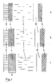
- Figure 1 shows the simple structure of the camouflage film in three different settings.
- An infrared-transparent, dielectric interference layer 4 is located on a preferably infrared-transparent carrier film 2 (for example made of polyethylene).
- the film covers the object 6 to be camouflaged against an observer.
- a protective layer 8 can optionally be used; in any case, it must be transparent in the IR frequency range of the application.
- the area 10 represents the air space between the film and the object.
- the layer thickness d of the interference layer determines the amount of heat radiation, the emissivity, the overall arrangement of film and object.
- ⁇ is related to the center of the atmospheric window (approximately 4 ⁇ m and 10 ⁇ m). This is a low IR permeability and a low heat radiation from the object to be camouflaged and camouflage film aims.
- the opposite extreme case high emission, high surface temperature is set by the arrangement according to FIG. 1c and a medium state according to FIG. 1b.
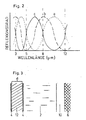
- FIG. 2 shows the spectral course of the reflectance of the three arrangements outlined in FIG. 1. It can be seen how the reflection maxima are shifted in relation to the atmospheric windows and how the described effect arises.
- the selection is based on the required transmission range in the infrared and optical spectrum, as well as on practical and technical aspects such as manufacturability, durability and costs.
- the group of semiconductors such as silicon, germanium, graphite, as well as metal sulfides, metal selenides and metal tellurides, which are also used as raw materials for compact IR windows, offers broadband camouflage and good stability. If transparency in the optical field is additionally desired, oxidic materials such as SiO2, Al2O3, SnO2, In2O3, TiO2, CeO2, MgO, fluorides such as MgF2, PbF2, BaF2 and other compounds with similar properties can be used.
- the refractive index of the layer and its dispersion i.e. its spectral course.
- High refractive indices are generally advantageous since the required layer thickness decreases with increasing n and the camouflage effect is still present even at increasingly oblique viewing angles.
- the dispersion must be taken into account if a simultaneous effect in both atmospheric windows is to be optimized.
- n3 average refractive index in the 3rd atmospheric window
- FIG. 3 shows, instead of a compact inference layer, the use of a multilayer system in which two thinner films 4 with a high refractive index are separated by the layer 12 with a low refractive index at a distance d.
- a transparent plastic film can be used as the layer 12, which is, for example, identical to the carrier film 2.
- the layers 4 can be made much thinner than the above ⁇ / 4 layers, so that the arrangement is given greater flexibility, which has a very advantageous effect for many applications.
- the optical effect of this arrangement corresponds to the one-layer interference.
- the air gap 10 is located between the carrier film 2 and the object 6 to be camouflaged.
- the camouflage film according to the invention can be used very advantageously for cladding radomes (radomes).
- radomes cladding radomes
- the current construction of radomes has proven to be extremely unfavorable in terms of detectability in the IR range. Due to the low thermal conductivity and heat capacity of the radome outer skin (plastic foam material or foils), the surface temperature is subject to strong weather-related fluctuations, which gives these objects an unusually well-defined thermal image signature. Countermeasures with conventional camouflage means without impairing the radar transmission are not known.
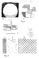
- FIG. 4a shows a typical signature of a radome in the sun.
- the upper half of the sphere is warmed up and stands out against the much darker background.
- the light-dark conditions are just the other way around due to the low sky temperature, but just as easily recognizable.
- effective contour decomposition is brought about by typical structures of the surroundings, such as rectangular ones Areas in agricultural fields ( Figure 4b, without background) or settlements, building structures ( Figure 4c) or other landscape formations (horizon lines, ranges of hills, forest areas, river courses) can be simulated.
- camouflage film according to the invention does not have to be present at all times — like a coat of paint — since, if necessary, it can be spread out and removed again very quickly. For some objects, such as roads and airfield systems, this is the only conceivable solution.
- FIG. 5 shows a cross section through this arrangement.
- the IR-active camouflage film with plastic carrier 2 and interference layer 4 is connected directly to the radar absorber material 14.
- the above-mentioned variants for contour decomposition and signature simulation can of course also be used advantageously here.
- An additional camouflage effect in the visible or near infrared is possible by using colored plastic films. If foils with good optical transparency are used, then the visual camouflage effect can be achieved by means of deposited and thus easily changed paint coats, or it is already given by the existing camouflage of the object.
- camouflage film according to the invention In the conceivable application of the camouflage film according to the invention to vehicles, ships, airplanes, steel bridges, steel masts and the like, there is a special aspect. Due to their predominantly metal structure, these objects have a clear and characteristic radar signature. This problem can basically be solved by using radar absorbers and multispectral camouflage film, as described above. However, if radar absorbers are not desired or not possible for any reason (weight, cost, availability), then a combined IR-radar camouflage effect can be achieved with the camouflage film according to the invention by metallizing the film over the whole or part of the object. In this way, certain characteristic radar signatures of the object can be canceled or falsified.
Abstract
Description
Die Erfindung betrifft eine Kunststoff-Folie mit niedrigem Emissionsgrad im 2. und 3. atmosphärischen Fenster und hoher Transparenz in anderen Spektralbereichen, beispielsweise gegenüber Mikrowellen. Die Tarnfolie eignet sich aufgrund ihrer speziellen Merkmale
- als einfache, auswechselbare,niedrigemittierende Beschichtung,
- zur Wärmebildtarnung von ortsfesten Anlagen, insbesondere Radomen,
- als universelle Komponente in multispektralen Tarnsystemen.The invention relates to a plastic film with a low emissivity in the 2nd and 3rd atmospheric window and high transparency in other spectral ranges, for example compared to microwaves. The camouflage film is suitable due to its special features
- as a simple, exchangeable, low-emissive coating,
- for thermal imaging camouflage of fixed systems, especially radomes,
- as a universal component in multispectral camouflage systems.
Die Tarnung von Objekten gegen Aufklärung durch Wärmebildgeräte enthält eine besondere Problematik. Anders als im Sichtbaren ist im thermischen Infrarot-Bereich die Erkenn barkeit eines Objektes nicht nur von dessen Oberflächeneigenschaften (wie Farbe, Reflexionsgrad, Rauhigkeit) abhängig, sondern wird zusätzlich durch die Temperatur der Oberfläche und die Temperaturen der Umgebung,des Hintergrundes und des Himmels bestimmt.The camouflage of objects against reconnaissance by thermal imaging devices contains a special problem. Unlike in the visible, detection is in the thermal infrared range Ability of an object not only depends on its surface properties (such as color, degree of reflection, roughness), but is also determined by the temperature of the surface and the temperatures of the surroundings, the background and the sky.
Zur Tarnung werden niedrigemittierende Anstriche eingesetzt. Diese Maßnahme verringert proportional zur Höhe des Emissionsgrades ε der Oberfläche, die von diesem Objekt ausgehende Wärmestrahlung; besonders bei stärker erwärmten Objekten kann auf diese Weise eine Minderung der Entdeckbarkeit erreicht werden.Low emissive coatings are used for camouflage. This measure reduces, proportionally to the level of emissivity ε of the surface, the heat radiation emanating from this object; In this way, the detectability can be reduced, particularly in the case of objects that are warmed up more.
Neben den Anstrichen sind andere Infrarot-Tarnmittel mit ähnlicher Wirkung bekannt: beispielsweise niedrigemittierende Textilien, kaschierte Metallfolien, Infrarot-Tarnnetze mit metallischen Elementen (Schichten, Folien, Fäden), galvanische,niedrigemittierende Beschichtungen und Ähnliches.In addition to the paints, other infrared camouflage agents with a similar effect are known: for example low-emitting textiles, laminated metal foils, infrared camouflage nets with metallic elements (layers, foils, threads), galvanic, low-emitting coatings and the like.
Gemeinsames Merkmal dieser infrarotaktiven Tarnmittel ist, dass die niedrigemittierende Wirkung durch Einlagerung von metallischen Schichten oder Partikeln erreicht wird. Niedrige Infrarot-Emissionsgrade unter etwa 70 % treten an homogenen Materialien nur auf, wenn diese metallischen Charakter und eine gewisse metallische Leitfähigkeit besitzen.A common feature of these infrared-active camouflage agents is that the low-emitting effect is achieved by incorporating metallic layers or particles. Low infrared emissivities below about 70% only occur on homogeneous materials if they have a metallic character and a certain metallic conductivity.
Herkömmliche metallhaltige IR-Tarnanstriche und IR-Tarnmittel besitzen einige typische Nachteile, welche ihre Verwendungsmöglichkeiten und Wirksamkeit stark einschränken:
Die Metallkomponente bewirkt, dass die Schichten für elektromagnetische Strahlung allgemein undurchlässig sind und starke Reflexionswirkung zeigen. Im sichtoptischen Bereich wird die unerwünschte Reflexion üblicherweise mit Hilfe von Farbpigmenten unterdrückt, dies ist jedoch im Mikrowellen- und Radiowellenbereich nicht möglich, so dass diese IR-Tarnmittel gegenüber Radaraufklärung keine tarnende Wirkung zeigen oder die Entdeckbarkeit eher noch erhöht wird, wenn das Objekt selbst radarneutral ist.Conventional metal-containing IR camouflage paints and IR camouflage agents have some typical disadvantages, which severely limit their possible uses and effectiveness:
The metal component has the effect that the layers are generally opaque to electromagnetic radiation and show a strong reflection effect. In the optical field, the undesired reflection is usually suppressed with the help of color pigments, but this is not possible in the microwave and radio wave range, so that these IR camouflaging agents have no camouflaging effect compared to radar reconnaissance or the detectability is rather increased if the object itself is radar-neutral is.
Aus dem gleichen Grund können herkömmliche niedrigemittierende Schichten nicht zur Tarnung von Kommunikationsanlagen wie Sende- und Empfangsantennen, Radarkuppeln und anderen entsprechenden Einrichtungen verwendet werden.For the same reason, conventional low-emissivity layers cannot be used to camouflage communication systems such as transmitting and receiving antennas, radar domes and other corresponding devices.
Der vorliegenden Erfindung liegt die Aufgabe zugrunde, ein multispektral wirksames Tarnmittel zu schaffen.The present invention has for its object to provide a multispectral camouflage agent.
Diese Aufgabe wird erfindungsgemäss mit Hilfe einer beschichteten Kunststoff-Folie gelöst, wobei die Beschichtung aus nichtmetallischem, infrarottransparentem Material besteht und die Schichtdicke im Verhältnis zum Brechnungsindex so einge stellt wird, dass aufgrund von Interferenzeffekten die Wärmeabstrahlung im 2. und/oder 3. atmosphärischen Fenster reduziert wird. Die Anordnung besitzt eine hohe Durchlässigkeit für Strahlung im Mikrowellen- und Radiowellenbereich und je nach Ausführungsform auch in anderen Spektralbereichen (sichtbares Licht, nahes Infrarot), so dass die multispektrale Tarnwirkung gewährleistet bzw. nicht behindert wird.This object is achieved according to the invention with the aid of a coated plastic film, the coating consisting of non-metallic, infrared-transparent material and the layer thickness in relation to the refractive index thus reduced it is established that due to interference effects, the heat radiation in the 2nd and / or 3rd atmospheric window is reduced. The arrangement has a high permeability to radiation in the microwave and radio wave range and, depending on the embodiment, also in other spectral ranges (visible light, near infrared), so that the multispectral camouflage effect is guaranteed or not impeded.
Durch Aneinanderreihung von mehreren Foliensegmenten mit unterschiedlicher Abstrahlung (Emissionsgraden) und geeigneter geometrischer Form können auf einfache Weise weitere Tarneffekte durch Konturenzerlegung oder Erzeugung beliebiger Infrarotsignaturen erzielt werden.By lining up several film segments with different radiation (emissivities) and a suitable geometric shape, additional camouflage effects can be easily achieved by breaking down contours or generating any infrared signature.
Die Erfindung wird anhand von Figuren nachfolgend näher beschrieben.The invention is described in more detail below with reference to figures.
Es zeigen:
Figur 1 Schnitte durch den Aufbau der Folien in drei Ausführungsformen,Figur 2 den Spektralverlauf des Reflexionsgrades der drei Ausführungen inFigur 1,Figur 3 den Einsatz eines Mehrschichtensystems als Folienaufbau,Figur 4 die Darstellung einer Kuppel und die Möglichkeit der Simulation nichtvorhandener Strukturen auf der Kuppel,Figur 5 einen Schnitt durch den Aufbau einer Radarabsorbereinrichtung.
- FIG. 1 sections through the construction of the foils in three embodiments,
- FIG. 2 shows the spectral profile of the reflectance of the three versions in FIG. 1,
- FIG. 3 the use of a multilayer system as a film structure,
- Figure 4 shows a dome and the possibility the simulation of nonexistent structures on the dome,
- 5 shows a section through the structure of a radar absorber device.
Die Figur 1 zeigt den einfachen Aufbau der Tarnfolie in drei verschiedenen Einstellungen. Auf einer vorzugsweise infrarottransparenten Trägerfolie 2 (beispielsweise aus Polyethylen) befindet sich eine infrarottransparente, dielektrische Interferenzschicht 4. Die Folie deckt das zu tarnende Objekt 6 gegen einen Beobachter ab. Eine Schutzschicht 8 kann wahlweise eingesetzt werden, sie muss in jedem Fall im IR-Frequenzbereich der Anwendung transparent sein. Der Bereich 10 stellt den Luftraum zwischen Folie und Objekt dar.
Die Schichtdicke d der Interferenzschicht bestimmt bei vorgegebenem Schichtmaterial die Höhe der Wärmeabstrahlung, den Emissionsgrad, der Gesamtanordnung Folie und Objekt. Soll eine besonders niedrige Abstrahlung, also eine kalte Oberfläche simuliert werden, so ist die Dicke etwa auf dem Wert d = λ/(4 · n) (Figur 1a) einzustellen, wobei n Brechungsindex der Schicht und λ Wellenlänge der Abstrahlung bedeutet. In der Regel wird λ auf das Zentrum der atmosphärischen Fenster (etwa 4 µm und 10 µm) bezogen.
Damit ist eine niedrige IR-Durchlässigkeit und eine niedrige Wärmeabstrahlung von zu tarnendem Objekt und Tarnfolie er zielt.
Der entgegengesetzte Extremfall (hohe Emission, hohe Oberflächentemperatur) wird durch die Anordnung gemäss Figur 1c und ein mittlerer Zustand gemäss Figur 1b eingestellt.
In Figur 1b berechnet sich die Dicke d zu d = 3 ·λ /(8 · n) und in Figur 1c erhält d den Wert d = λ /(2 · n).
Alle weiteren Zwischenzustände sind auf diese Weise ohne Weiteres realisierbar.Figure 1 shows the simple structure of the camouflage film in three different settings. An infrared-transparent,
For a given layer material, the layer thickness d of the interference layer determines the amount of heat radiation, the emissivity, the overall arrangement of film and object. If a particularly low radiation, that is to say a cold surface, is to be simulated, the thickness should be set approximately to the value d = λ / (4 · n) (FIG. 1a), where n means the refractive index of the layer and λ wavelength of the radiation. As a rule, λ is related to the center of the atmospheric window (approximately 4 µm and 10 µm).
This is a low IR permeability and a low heat radiation from the object to be camouflaged and camouflage film aims.
The opposite extreme case (high emission, high surface temperature) is set by the arrangement according to FIG. 1c and a medium state according to FIG. 1b.
In FIG. 1b the thickness d is calculated as d = 3 · λ / (8 · n) and in FIG. 1c d is given the value d = λ / (2 · n).
All other intermediate states can be easily implemented in this way.
Figur 2 zeigt zur Verdeutlichung den Spektralverlauf des Reflexionsgrades der drei in Figur 1 skizzierten Anordnungen. Erkennbar ist, wie die Reflexionsmaxima im Verhältnis zu den atmosphärischen Fenstern verschoben werden und dadurch die beschriebene Wirkung entsteht.For clarification, FIG. 2 shows the spectral course of the reflectance of the three arrangements outlined in FIG. 1. It can be seen how the reflection maxima are shifted in relation to the atmospheric windows and how the described effect arises.
Die Figuren 1 und 2 beschreiben die Situation für Interferenzen an einer Schicht. Reflexmindernde und reflexerhöhende Wirkungen können durch Einsatz von Systemen mit zwei und mehr interferierenden Schichten noch weiter gesteigert werden. Die Praxis der Infrarot-Tarnung zeigt jedoch, dass in den meisten Fällen nicht die Extremwerte, sondern mittlere Emissionsgrade von ε = 30 - 70% vorteilhaft sind, die mit der Einschicht-Interferenz erzeugt werden können.Figures 1 and 2 describe the situation for interference on a layer. Reflex-reducing and reflex-enhancing effects can be increased even further by using systems with two or more interfering layers. However, the practice of infrared camouflage shows that in most cases it is not the extreme values, but rather average emissivities of ε = 30 - 70% that can be generated with the single-layer interference that are advantageous.
Als mögliches Schichtmaterial kommt eine grössere Anzahl von Substanzen in Betracht. Die Auswahl richtet sich nach dem geforderten Transmissionsbereich im infraroten und im sichtoptischen Spektrum, sowie nach praktischen und technischen Gesichtspunkten wie Herstellbarkeit, Haltbarkeit und Kosten. Breitbandige Tarnwirkung und gute Stabilität bietet die Gruppe der Halbleiter wie Silizium, Germanium, Graphit, sowie Metallsulfide, Metallselenide und Metalltelluride, die auch als Rohstoff für kompakte IR-Fenster herangezogen werden. Wird zusätzlich die Transparenz im sichtoptischen Bereich gewünscht, sind oxidische Materialien wie beispielsweise SiO₂, Al₂O₃, SnO₂, In₂O₃, TiO₂, CeO₂, MgO, Fluoride wie MgF₂, PbF₂, BaF₂ und andere Verbindungen mit ähnlichen Eigenschaften einsetzbar.A larger number comes as a possible layer material of substances into consideration. The selection is based on the required transmission range in the infrared and optical spectrum, as well as on practical and technical aspects such as manufacturability, durability and costs. The group of semiconductors such as silicon, germanium, graphite, as well as metal sulfides, metal selenides and metal tellurides, which are also used as raw materials for compact IR windows, offers broadband camouflage and good stability. If transparency in the optical field is additionally desired, oxidic materials such as SiO₂, Al₂O₃, SnO₂, In₂O₃, TiO₂, CeO₂, MgO, fluorides such as MgF₂, PbF₂, BaF₂ and other compounds with similar properties can be used.
Ein weiteres wichtiges Kriterium für die Stoffauswahl ist der Brechungsindex der Schicht und seine Dispersion, das heisst sein Spektralverlauf. Hohe Brechungsindizes sind generell vorteilhaft, da mit steigendem n die erforderliche Schichtdicke abnimmt und die Tarnwirkung auch bei zunehmend schrägen Blickwinkeln noch vorhanden ist. Die Dispersion muss berücksichtigt werden, wenn eine simultane Wirkung in beiden atmosphärischen Fenstern optimiert werden soll. Wird z.B. eine Schicht auf maximale Reflexion (geringe Emission) bei λ₃ = 10 µm eingestellt (d = λ₃/(4 · n₃); n₃ = mittlerer Brechungsindex im 3. atmosphärischen Fenster)), so hat diese Schicht auch ein Reflexionsmaximum im 2. atmosphärischen Fenster, dessen genaue Lage vom Brechungsindex n₂ (bei 3 - 5 µm) abhängt:
Figur 3 zeigt statt einer kompakten Inferferenzschicht den Einsatz eines Mehrschichtensystems, bei dem zwei dünnere Filme 4 mit hohem Brechungsindex im Abstand d durch die Schicht 12 mit niedrigem Brechungsindex getrennt sind. Der besondere Vorteil dieser Ausführungsform liegt darin, dass als Schicht 12 eine transparente Kunststoff-Folie verwendet werden kann, die z.B. identisch mit der Trägerfolie 2 ist. Die Schichten 4 können in diesem Fall sehr viel dünner als die obigen λ/4-Schichten ausgeführt werden, so dass die Anordnung eine höhere Flexibilität erhält, was sich für viele Anwendungen sehr vorteilhaft auswirkt. Die optische Wirkung dieser Anordnung entspricht jedoch der Einschicht-Interferenz. Zwischen Trägerfolie 2 und zu tarnendem Objekt 6 befindet sich der Luftzwischenraum 10.FIG. 3 shows, instead of a compact inference layer, the use of a multilayer system in which two
Weitere Merkmale und Vorzüge der Erfindung sollen anhand typischer Anwendungen beschrieben werden.Further features and advantages of the invention are to be described on the basis of typical applications.
Die erfindungsgemässe Tarnfolie kann sehr vorteilhaft zur Verkleidung von Radarkuppeln (Radome) eingesetzt werden. Die heutige Bauweise von Radomen hat sich im Hinblick auf die Detektierbarkeit im IR-Bereich als ausgesprochen ungünstig erwiesen. Aufgrund der geringen Wärmeleitfähigkeit und Wärmekapazität der Radomaussenhaut (Kunststoff-Schaummaterial oder -Folien) ist die Oberflächentemperatur starken witterungsbedingten Schwankungen unterworfen, was diesen Objekten eine ungewöhnlich gut ausgeprägte Wärmebildsignatur verleiht. Gegenmaßnahmen mit herkömmlichen Tarnmitteln ohne Beeinträchtigung der Radartransmission sind nicht bekannt.The camouflage film according to the invention can be used very advantageously for cladding radomes (radomes). The current construction of radomes has proven to be extremely unfavorable in terms of detectability in the IR range. Due to the low thermal conductivity and heat capacity of the radome outer skin (plastic foam material or foils), the surface temperature is subject to strong weather-related fluctuations, which gives these objects an unusually well-defined thermal image signature. Countermeasures with conventional camouflage means without impairing the radar transmission are not known.
Die Figur 4 zeigt symbolisiert diesen Anwendungsfall. In Figur 4a ist eine typische Signatur eines Radoms bei Sonneneinstrahlung gezeigt. Die obere Hälfte der Kugel ist stark erwärmt und hebt sich charakteristisch gegen den viel dunkleren Hintergrund ab. Bei Nacht sind die Hell-Dunkel-Verhältnisse wegen der niedrigen Himmelstemperatur gerade umgekehrt, aber ebenso gut erkennbar. Mit Hilfe der erfindungsgemässen, an der Aussenfläche des Radoms angebrachten Folie, wird eine wirkungsvolle Konturenzerlegung hervorgerufen, indem typische Strukturen der Umgebung wie z.B. rechteckige Flächen bei landwirtschaftlichen Feldern (Figur 4b, ohne Hintergrund) oder Siedlungen, Gebäudestrukturen (Figur 4c) oder sonstige Landschaftsformationen (Horizontlinien, Hügelketten, Waldflächen, Flußläufe) simuliert werden.Figure 4 symbolizes this application. FIG. 4a shows a typical signature of a radome in the sun. The upper half of the sphere is warmed up and stands out against the much darker background. At night, the light-dark conditions are just the other way around due to the low sky temperature, but just as easily recognizable. With the aid of the film according to the invention, which is attached to the outer surface of the radome, effective contour decomposition is brought about by typical structures of the surroundings, such as rectangular ones Areas in agricultural fields (Figure 4b, without background) or settlements, building structures (Figure 4c) or other landscape formations (horizon lines, ranges of hills, forest areas, river courses) can be simulated.
Eine ähnliche Situation liegt vor bei der Tarnung von anderen Anlagen und Komponenten der Übertragungstechnik, also Rundfunksendern, Fernmeldestationen, Satellitenempfangsantennen, Funkleitsystemen oder Peil- und Aufklärungssystemen). Alle diese im Verteidigungsfall unentbehrlichen Anlagen, die bisher als leicht erkennbar und verwundbar gelten, können mit Hilfe der Erfindung wirksam gegen Wärmebildaufklärung getarnt werden, ohne jede Beeinträchtigung ihrer Funktion.A similar situation exists with the camouflage of other systems and components of the transmission technology (i.e. radio transmitters, telecommunications stations, satellite reception antennas, radio control systems or direction finding and reconnaissance systems). All of these systems, which are indispensable in the event of a defense and which have hitherto been regarded as easily recognizable and vulnerable, can be effectively camouflaged with the aid of the invention against thermal imaging without any impairment of their function.
Weitere Anwendungen liegen bei der IR-Tarnung von Gebäuden, Strassen, Brücken und ähnlichen Einrichtungen; ebenfalls strategisch sehr wichtige Objekte, die bisher gegenüber der Wärmebildbeobachtung nicht oder nur auf Kosten erhöhter Radarerkennbarkeit zu schützen sind. Vorteilhaft hierbei ist auch, dass die erfindungsgemässe Tarnfolie nicht ständig - wie ein Anstrich - vorhanden sein muss, da sie im Bedarfsfall sehr schnell ausgebreitet und wieder entfernt werden kann. Für manche Objekte, wie beispielsweise Strassen und Flugplatzanlagen, stellt dies die einzig denkbare Lösung dar.Other applications are in the IR camouflage of buildings, roads, bridges and similar facilities; Also strategically very important objects, which so far have not been able to be protected against thermal imaging observation or only at the expense of increased radar detectability. It is also advantageous here that the camouflage film according to the invention does not have to be present at all times — like a coat of paint — since, if necessary, it can be spread out and removed again very quickly. For some objects, such as roads and airfield systems, this is the only conceivable solution.
Eine Anwendung, bei der die Durchlässigkeit im Mikrowellenbereich ebenfalls als entscheidende Voraussetzung eingeht, sind radarabsorbierende Materialien und Strukturen. Diese heute bekannten Tarnmittel gegen Radaraufklärung sind ausnahmslos gute IR-Emitter und deshalb im Wärmebild leicht detektierbar, andererseits aber mit niedrigemittierenden Anstrichen auf Metallbasis nicht zu behandeln, da dann die Radarabsorberwirkung verlorengeht.An application in which the permeability in the microwave range is also a crucial requirement is radar-absorbing materials and structures. These camouflaging agents known today against radar detection are invariably good IR emitters and therefore easy to detect in the thermal image, but on the other hand they cannot be treated with low-emitting paints based on metal, since the radar absorber effect is then lost.
Die Figur 5 zeigt einen Querschnitt durch diese Anordnung. Die IR-aktive Tarnfolie mit Kunststoffträger 2 und Interferenzschicht 4 ist direkt mit dem Radarabsorbermaterial 14 verbunden. Die oben erwähnten Varianten zur Konturenzerlegung und Signatursimulation können natürlich auch hier vorteilhaft eingesetzt werden.
Eine zusätzliche Tarnwirkung im Sichtbaren oder nahen Infrarot ist durch Verwendung eingefärbter Kunststoff-Folien möglich. Werden Folien mit guter optischer Transparenz eingesetzt, dann kann die visuelle Tarnwirkung durch hinterlegte und damit leicht veränderbare Farbanstriche erreicht werden, oder sie ist durch den vorhandenen Tarnanstrich des Objekts bereits gegeben.FIG. 5 shows a cross section through this arrangement. The IR-active camouflage film with
An additional camouflage effect in the visible or near infrared is possible by using colored plastic films. If foils with good optical transparency are used, then the visual camouflage effect can be achieved by means of deposited and thus easily changed paint coats, or it is already given by the existing camouflage of the object.
Bei der denkbaren Anwendung der erfindungsgemässen Tarnfolie auf Fahrzeuge, Schiffe, Flugzeuge, Stahlbrücken, Stahlmaste und Ähnlichem, kommt ein besonderer Aspekt dazu. Diese Objekte weisen aufgrund ihrer vorwiegend aus Metall bestehenden Struktur eine deutliche und charakteristische Radarsignatur auf. Dieses Problem kann grundsätzlich durch Anwendung von Radarabsorbern und multispektraler Tarnfolie, wie oben beschrieben, gelöst werden. Sind jedoch Radarabsorber aus irgendwelchen Gründen (Gewicht, Kosten, Verfügbarkeit) nicht erwünscht oder nicht möglich, dann kann mit Hilfe der erfindungsgemässsen Tarnfolie ein kombinierter IR-Radar-Tarneffekt dadurch erzielt werden, dass die Folie objektseitig ganzflächig oder teilweise metallisiert wird. Bestimmte charakteristische Radarsignaturen des Objektes können auf diese Weise aufgehoben oder verfälscht werden.In the conceivable application of the camouflage film according to the invention to vehicles, ships, airplanes, steel bridges, steel masts and the like, there is a special aspect. Due to their predominantly metal structure, these objects have a clear and characteristic radar signature. This problem can basically be solved by using radar absorbers and multispectral camouflage film, as described above. However, if radar absorbers are not desired or not possible for any reason (weight, cost, availability), then a combined IR-radar camouflage effect can be achieved with the camouflage film according to the invention by metallizing the film over the whole or part of the object. In this way, certain characteristic radar signatures of the object can be canceled or falsified.
Claims (8)
Applications Claiming Priority (2)
| Application Number | Priority Date | Filing Date | Title |
|---|---|---|---|
| DE3614017 | 1986-04-25 | ||
| DE19863614017 DE3614017A1 (en) | 1986-04-25 | 1986-04-25 | MULTI-SPECTRAL CAMOUFLAGE |
Publications (2)
| Publication Number | Publication Date |
|---|---|
| EP0250741A1 true EP0250741A1 (en) | 1988-01-07 |
| EP0250741B1 EP0250741B1 (en) | 1989-12-13 |
Family
ID=6299516
Family Applications (1)
| Application Number | Title | Priority Date | Filing Date |
|---|---|---|---|
| EP87105583A Expired EP0250741B1 (en) | 1986-04-25 | 1987-04-15 | Multi-spectral camouflage sheet |
Country Status (2)
| Country | Link |
|---|---|
| EP (1) | EP0250741B1 (en) |
| DE (2) | DE3614017A1 (en) |
Cited By (2)
| Publication number | Priority date | Publication date | Assignee | Title |
|---|---|---|---|---|
| FR2857458A1 (en) * | 2003-07-09 | 2005-01-14 | Centre Nat Rech Scient | Directional thermal radiation emitting structure, has internal layer made up of material having predetermined refractive index that satisfies predetermined equation in spectral band |
| CN111435065A (en) * | 2019-08-15 | 2020-07-21 | 宁波曙翔新材料股份有限公司 | Device for changing camouflage mode of camouflage equipment and application thereof |
Families Citing this family (6)
| Publication number | Priority date | Publication date | Assignee | Title |
|---|---|---|---|---|
| DE4012782A1 (en) * | 1990-04-21 | 1991-10-24 | Telefunken Systemtechnik | ABSORBER |
| DE4330224C2 (en) * | 1993-09-07 | 1996-04-18 | Daimler Benz Aerospace Ag | Radome for radar systems |
| DE4341806C1 (en) * | 1993-12-08 | 1995-06-08 | Daimler Benz Aerospace Ag | Self support radome |
| DE9408490U1 (en) * | 1994-05-25 | 1995-09-28 | Ernst Fehr Tech Vertretungen U | Radiation shield protection pad |
| EP0737840A3 (en) * | 1995-04-07 | 1996-11-13 | Daimler-Benz Aerospace Aktiengesellschaft | Method and device for camouflage |
| CA2272126C (en) * | 1997-02-12 | 2005-08-09 | Schweizerische Eidgenossenschaft, Eidgenossisches Militardepartement, Gr Uppe Rustung | Camouflage structure |
Citations (2)
| Publication number | Priority date | Publication date | Assignee | Title |
|---|---|---|---|---|
| DE3043381C2 (en) * | 1980-11-18 | 1982-11-11 | Dornier System Gmbh, 7990 Friedrichshafen | Use of spectrally selectively coated surfaces and processes for their production |
| DE3217977A1 (en) * | 1982-05-13 | 1983-11-17 | Bundesrepublik Deutschland, vertreten durch den Bundesminister der Verteidigung, dieser vertreten durch den Präsidenten des Bundesamtes für Wehrtechnik und Beschaffung, 5400 Koblenz | Device for camouflaging objects against reconnaissance by thermal imagers |
Family Cites Families (2)
| Publication number | Priority date | Publication date | Assignee | Title |
|---|---|---|---|---|
| NL273666A (en) * | 1961-02-02 | |||
| US4529633A (en) * | 1983-01-14 | 1985-07-16 | Diab-Barracuda Ab | Thermal camouflage |
-
1986
- 1986-04-25 DE DE19863614017 patent/DE3614017A1/en not_active Withdrawn
-
1987
- 1987-04-15 EP EP87105583A patent/EP0250741B1/en not_active Expired
- 1987-04-15 DE DE8787105583T patent/DE3761171D1/en not_active Expired - Fee Related
Patent Citations (2)
| Publication number | Priority date | Publication date | Assignee | Title |
|---|---|---|---|---|
| DE3043381C2 (en) * | 1980-11-18 | 1982-11-11 | Dornier System Gmbh, 7990 Friedrichshafen | Use of spectrally selectively coated surfaces and processes for their production |
| DE3217977A1 (en) * | 1982-05-13 | 1983-11-17 | Bundesrepublik Deutschland, vertreten durch den Bundesminister der Verteidigung, dieser vertreten durch den Präsidenten des Bundesamtes für Wehrtechnik und Beschaffung, 5400 Koblenz | Device for camouflaging objects against reconnaissance by thermal imagers |
Cited By (3)
| Publication number | Priority date | Publication date | Assignee | Title |
|---|---|---|---|---|
| FR2857458A1 (en) * | 2003-07-09 | 2005-01-14 | Centre Nat Rech Scient | Directional thermal radiation emitting structure, has internal layer made up of material having predetermined refractive index that satisfies predetermined equation in spectral band |
| CN111435065A (en) * | 2019-08-15 | 2020-07-21 | 宁波曙翔新材料股份有限公司 | Device for changing camouflage mode of camouflage equipment and application thereof |
| CN111435065B (en) * | 2019-08-15 | 2023-06-27 | 宁波曙翔新材料股份有限公司 | Device for changing camouflage pattern of camouflage equipment and application thereof |
Also Published As
| Publication number | Publication date |
|---|---|
| DE3761171D1 (en) | 1990-01-18 |
| EP0250741B1 (en) | 1989-12-13 |
| DE3614017A1 (en) | 1987-10-29 |
Similar Documents
| Publication | Publication Date | Title |
|---|---|---|
| EP0250742B1 (en) | Radar-transparent sheet with controllable infra-red reflection for camouflage purposes | |
| EP0468173B1 (en) | Camouflage net | |
| DE1916326A1 (en) | Camouflage means for preventing or inhibiting detection by radar reconnaissance | |
| EP0250741B1 (en) | Multi-spectral camouflage sheet | |
| DE60111889T2 (en) | Silicon thermal insulation blanket | |
| US5950237A (en) | Jacket for the personal protection of an infantryman | |
| DE4418214C2 (en) | Paint with low emissivity in the area of thermal radiation | |
| DE2700202C1 (en) | Broadband camouflage | |
| DE3135586C2 (en) | ||
| AT391728B (en) | MULTI-LAYER SYSTEM FOR HEAT PROTECTION APPLICATION | |
| EP0912875B1 (en) | Camouflage structure | |
| DE112020005531T5 (en) | Heat shield sheet and vehicle with heat shield sheet | |
| DE4400512C2 (en) | Rigid insulating sleeve for a gun barrel | |
| EP1102028A2 (en) | Infra-red camouflage system | |
| EP0137930A2 (en) | Protective coat or window | |
| DE19710692C2 (en) | Multispectral camouflage element | |
| DE19955608C2 (en) | Infrared cloaking device | |
| DE3148429A1 (en) | IR camouflage device for aircraft | |
| EP1990600A2 (en) | Security system against damaging pressure waves for military equipment such as radar coverings and armour | |
| WO2020208057A1 (en) | Radar antenna | |
| WO2020260372A1 (en) | Method and device for sensing a spatial region by means of radar waves | |
| DE4216837C2 (en) | Radar camouflage for slow-flying roll-stabilized missiles | |
| DE2103077A1 (en) | Thermal camouflage | |
| DE2807163C3 (en) | Antenna for transmitting and / or receiving high-frequency electromagnetic and optical radiation | |
| DE102009019635A1 (en) | Optical element for e.g. use as translucent delimitation of e.g. roof, of building, has optically diffuse reflecting segments arranged on light incident and light emission surfaces of optically transparent substrate |
Legal Events
| Date | Code | Title | Description |
|---|---|---|---|
| PUAI | Public reference made under article 153(3) epc to a published international application that has entered the european phase |
Free format text: ORIGINAL CODE: 0009012 |
|
| AK | Designated contracting states |
Kind code of ref document: A1 Designated state(s): CH DE FR GB IT LI SE |
|
| 17P | Request for examination filed |
Effective date: 19880202 |
|
| 17Q | First examination report despatched |
Effective date: 19880929 |
|
| RAP1 | Party data changed (applicant data changed or rights of an application transferred) |
Owner name: DORNIER GMBH |
|
| GRAA | (expected) grant |
Free format text: ORIGINAL CODE: 0009210 |
|
| AK | Designated contracting states |
Kind code of ref document: B1 Designated state(s): CH DE FR GB IT LI SE |
|
| PG25 | Lapsed in a contracting state [announced via postgrant information from national office to epo] |
Ref country code: SE Effective date: 19891213 |
|
| GBT | Gb: translation of ep patent filed (gb section 77(6)(a)/1977) | ||
| REF | Corresponds to: |
Ref document number: 3761171 Country of ref document: DE Date of ref document: 19900118 |
|
| ET | Fr: translation filed | ||
| ITF | It: translation for a ep patent filed |
Owner name: JACOBACCI & PERANI S.P.A. |
|
| PG25 | Lapsed in a contracting state [announced via postgrant information from national office to epo] |
Ref country code: LI Effective date: 19900430 Ref country code: CH Effective date: 19900430 |
|
| PLBE | No opposition filed within time limit |
Free format text: ORIGINAL CODE: 0009261 |
|
| STAA | Information on the status of an ep patent application or granted ep patent |
Free format text: STATUS: NO OPPOSITION FILED WITHIN TIME LIMIT |
|
| 26N | No opposition filed | ||
| REG | Reference to a national code |
Ref country code: CH Ref legal event code: PL |
|
| ITTA | It: last paid annual fee | ||
| REG | Reference to a national code |
Ref country code: GB Ref legal event code: IF02 |
|
| PGFP | Annual fee paid to national office [announced via postgrant information from national office to epo] |
Ref country code: GB Payment date: 20030326 Year of fee payment: 17 |
|
| PGFP | Annual fee paid to national office [announced via postgrant information from national office to epo] |
Ref country code: DE Payment date: 20030331 Year of fee payment: 17 |
|
| PGFP | Annual fee paid to national office [announced via postgrant information from national office to epo] |
Ref country code: FR Payment date: 20030408 Year of fee payment: 17 |
|
| PG25 | Lapsed in a contracting state [announced via postgrant information from national office to epo] |
Ref country code: GB Free format text: LAPSE BECAUSE OF NON-PAYMENT OF DUE FEES Effective date: 20040415 |
|
| PG25 | Lapsed in a contracting state [announced via postgrant information from national office to epo] |
Ref country code: DE Free format text: LAPSE BECAUSE OF NON-PAYMENT OF DUE FEES Effective date: 20041103 |
|
| GBPC | Gb: european patent ceased through non-payment of renewal fee |
Effective date: 20040415 |
|
| PG25 | Lapsed in a contracting state [announced via postgrant information from national office to epo] |
Ref country code: FR Free format text: LAPSE BECAUSE OF NON-PAYMENT OF DUE FEES Effective date: 20041231 |
|
| REG | Reference to a national code |
Ref country code: FR Ref legal event code: ST |
|
| PG25 | Lapsed in a contracting state [announced via postgrant information from national office to epo] |
Ref country code: IT Free format text: LAPSE BECAUSE OF NON-PAYMENT OF DUE FEES;WARNING: LAPSES OF ITALIAN PATENTS WITH EFFECTIVE DATE BEFORE 2007 MAY HAVE OCCURRED AT ANY TIME BEFORE 2007. THE CORRECT EFFECTIVE DATE MAY BE DIFFERENT FROM THE ONE RECORDED. Effective date: 20050415 |