EP0250654B1 - Combine harvester - Google Patents
Combine harvester Download PDFInfo
- Publication number
- EP0250654B1 EP0250654B1 EP86201152A EP86201152A EP0250654B1 EP 0250654 B1 EP0250654 B1 EP 0250654B1 EP 86201152 A EP86201152 A EP 86201152A EP 86201152 A EP86201152 A EP 86201152A EP 0250654 B1 EP0250654 B1 EP 0250654B1
- Authority
- EP
- European Patent Office
- Prior art keywords
- module
- threshing
- separating
- cleaning
- grain
- Prior art date
- Legal status (The legal status is an assumption and is not a legal conclusion. Google has not performed a legal analysis and makes no representation as to the accuracy of the status listed.)
- Expired
Links
- 238000004140 cleaning Methods 0.000 claims description 198
- 239000010902 straw Substances 0.000 claims description 68
- 239000000463 material Substances 0.000 claims description 62
- 241001272996 Polyphylla fullo Species 0.000 claims description 27
- 238000013461 design Methods 0.000 claims description 5
- 238000003306 harvesting Methods 0.000 claims description 5
- 238000004064 recycling Methods 0.000 claims description 5
- 230000003534 oscillatory effect Effects 0.000 claims description 4
- 238000004891 communication Methods 0.000 claims description 3
- 230000000063 preceeding effect Effects 0.000 claims 4
- 235000013339 cereals Nutrition 0.000 description 78
- 230000007246 mechanism Effects 0.000 description 18
- 240000008042 Zea mays Species 0.000 description 6
- 235000005824 Zea mays ssp. parviglumis Nutrition 0.000 description 6
- 235000002017 Zea mays subsp mays Nutrition 0.000 description 6
- 235000005822 corn Nutrition 0.000 description 6
- 241001124569 Lycaenidae Species 0.000 description 5
- 238000013459 approach Methods 0.000 description 4
- 239000012535 impurity Substances 0.000 description 4
- 230000002411 adverse Effects 0.000 description 2
- 230000005540 biological transmission Effects 0.000 description 2
- 230000009977 dual effect Effects 0.000 description 2
- 210000005069 ears Anatomy 0.000 description 2
- 238000012545 processing Methods 0.000 description 2
- 238000012958 reprocessing Methods 0.000 description 2
- 235000007319 Avena orientalis Nutrition 0.000 description 1
- 244000075850 Avena orientalis Species 0.000 description 1
- 244000025254 Cannabis sativa Species 0.000 description 1
- 244000068988 Glycine max Species 0.000 description 1
- 235000010469 Glycine max Nutrition 0.000 description 1
- 240000005979 Hordeum vulgare Species 0.000 description 1
- 235000007340 Hordeum vulgare Nutrition 0.000 description 1
- 240000007594 Oryza sativa Species 0.000 description 1
- 235000007164 Oryza sativa Nutrition 0.000 description 1
- 241000209056 Secale Species 0.000 description 1
- 235000007238 Secale cereale Nutrition 0.000 description 1
- 241000209140 Triticum Species 0.000 description 1
- 235000021307 Triticum Nutrition 0.000 description 1
- 240000000359 Triticum dicoccon Species 0.000 description 1
- -1 chaff Substances 0.000 description 1
- 230000008878 coupling Effects 0.000 description 1
- 238000010168 coupling process Methods 0.000 description 1
- 238000005859 coupling reaction Methods 0.000 description 1
- 238000011161 development Methods 0.000 description 1
- 230000018109 developmental process Effects 0.000 description 1
- 230000003292 diminished effect Effects 0.000 description 1
- 239000000428 dust Substances 0.000 description 1
- 238000009434 installation Methods 0.000 description 1
- 230000001788 irregular Effects 0.000 description 1
- 239000002245 particle Substances 0.000 description 1
- 230000002035 prolonged effect Effects 0.000 description 1
- 235000009566 rice Nutrition 0.000 description 1
- 238000000926 separation method Methods 0.000 description 1
- 238000012549 training Methods 0.000 description 1
- 238000012546 transfer Methods 0.000 description 1
Images



Classifications
-
- A—HUMAN NECESSITIES
- A01—AGRICULTURE; FORESTRY; ANIMAL HUSBANDRY; HUNTING; TRAPPING; FISHING
- A01D—HARVESTING; MOWING
- A01D41/00—Combines, i.e. harvesters or mowers combined with threshing devices
-
- A—HUMAN NECESSITIES
- A01—AGRICULTURE; FORESTRY; ANIMAL HUSBANDRY; HUNTING; TRAPPING; FISHING
- A01D—HARVESTING; MOWING
- A01D67/00—Undercarriages or frames specially adapted for harvesters or mowers; Mechanisms for adjusting the frame; Platforms
Definitions
- the present invention relates to harvesting machines such as combine harvesters and more particularly is concerned with combine harvesters built following the modular concept.
- grain is threshed and separated in a threshing and separating mechanism and the separated grain, together with the impurities, such as chaff, dust, straw particles and tailings, is fed to a cleaning mechanism for cleaning.
- Clean grain is collected below the cleaning mechanism and fed to a grain tank for temporary storage.
- the tailings are separated from the clean grain and impurities for reprocessing. This reprocessing either involves recycling the tailings through the threshing and separating mechanism or treating them in a separate tailings rethreshing means.
- the rotatable threshing cylinder and cooperable concave extend transversely to the direction of movement of the combine.
- the crop is fed to the concave and passed between the concave and threshing cylinder whereby it is threshed.
- the straw is discharged rearwardly of the concave onto reciprocating or oscillating straw walkers that extend longitudinally of the combine.
- Much of the grain contained in the crop material fed to the threshing mechanism is threshed and separated by that mechanism and some of the remainder is separated from the straw whilst the latter is on the straw walkers.
- Straw walkers have proved to be the capacity-limiting components of the standard combine because, when operating at high capacity rates, much grain is discharged with the straw to the straw walkers which are unable to cope with the required separation, and hence unacceptable grain losses occur.
- a conventional transversely-extending, threshing mechanism having a threshing cylinder and a cooperable concave is combined with a rotary separating mechanism having a rotor of a width greater than that of the threshing mechanism and disposed parallel thereto with its ends extending transversely past the respective ends of the threshing mechanism.
- the rotary separating mechanism operates spirally to convey the crop material received from the threshing mechanism towards each of its ends, whilst submitting the crop to a separating action.
- the incoming layer of crop material has to be divided in two substantially equal portions, each of which is then spirally conveyed from the centre of the separating mechanism to one or other of its ends.
- the threshing and separating mechanism extends longitudinally (fore-and-aft) of the machine, parallel to the direction of movement and comprises at least one threshing and separating rotor and cooperable concave.
- the crop material is fed to the forward end of the threshing mechanism and is formed into a mat which passes generally axially therethrough in a spiral path.
- the crop material is subjected to a threshing and separating action far longer than in a standard machine of comparable size and, therefore, the efficiency of the former is greater than the efficiency of the latter.
- a combination of a modular design combine harvester and at least one replacement module therefore is provided wherein the combine harvester comprises, on the one hand, a first threshing module, a first separating module and a first cleaning module detachably connected to and in operative communication with each other and, on the other hand, grain storage means, a power source and an operator's station;
- forward used in connection with the combine harvester and/or components thereof are determined with reference to the direction of forward operative travel of this combine harvester but should not be considered as limiting.
- the combine harvester comprises the so-called base unit which basically consists of the entire machine less the header 1 and the straw elevator 6.
- the header as shown in the drawings is a so-called grainheader, but could be of any other type such as e.g. a corn header or a windrow pick-up attachment, depending on the type of crop and the condition of the crop to be harvested.
- the header 1 therefore conventionally forms a separate module and is detachably mounted on the forward end of the straw elevator 6.
- the header 1 shown in the drawings comprises a header trough 2 with cutter means (not shown) at its forward end and a header auger 3 rearwardly thereof.
- the header auger 3 is arranged to transversely consolidate harvested crop material and to convey this crop material through an outlet 4 disposed centrally in the rear wall of the header 1 and which communicates with the straw elevator 6.
- the header 1 conventionally further also comprises a reel 5 which is a further sub-assembly or module which is detachably mounted on the header trough 2 at a position above and partially forwardly of the cutter means and which may be interchangeable with a reel of a different type.
- the elevator 6 is formed as another sub-assembly which can easily be mounted at the forward end of the base unit generally at the threshing portion thereof and which can be adjusted angularly relative to the base unit by means of hydraulic lifting cylinders (not shown).
- the straw elevator 6 comprises a box-like framework of generally rectangular cross-section and houses conveyor means (not shown) which, in use, are operable to convey crop material received from the header 1 to the threshing means 7.
- the base unit of the combine harvester mainly comprises threshing means 7, separating means 8 and cleaning means 9.
- the threshing means 7 are operable to thresh crop material fed thereto, i.e. the crop material (which may be wheat, corn, rice, soybeans, rye, grass seed, barley, oats or other similar crops) is rubbed and beaten, whereby the grain, seed or the like, is loosened and separated from the straw, stalks, coils or other discardable part of the crop.
- the separating means 8 receive threshed crop material from the threshing means 7 and subject said crop material to a further separating action whereby grain not already separated from the rest of the crop material in the threshing means 7 is separated therefrom in said separating means 8. Grain which has been separated from the straw in the threshing means 7 and the separating means 8 is conveyed to the cleaning means 9 which is operable to separate chaff and other impurities from the grain on the one hand and to separate unthreshed or incompletely threshed material (known in the art as "tailings") from the clean grain on the other hand.
- Cleaned grain is then elevated into a graintank 10 and the tailings either are returned to the threshing means 7 for a repeat threshing action or are subjected to a renewed threshing action in separate tailings rethresher means whereafter said tailings are recycled through the cleaning means 9.
- the base unit further also comprises a power source 11 which is operatively coupled to the various machine components for driving these components and to combine propulsion means for making the combine harvester mobile.
- the combine harvester normally comprises a front pair of traction wheels 12 and a rear pair of steerable wheels 13.
- An operator's station 14 often provided within an operator's cab 15 and comprising an operator's seat 16 and all necessary controls, is provided generally at the forward end of the base unit and at a raised position so as to enable the operator, when positioned on the operator's station, to overview the harvesting operation of the header 1.
- the combine harvester further also comprises a strawhood 17 which is attachable to the rear of the machine.
- the invention is concerned basically, but not exclusively, with the threshing means 7, the separating means 8 and the cleaning means 9 which are provided in modules; said modules being interchangeable with other modules comprising respectively different types of threshing means 7, separating means 8 and cleaning means 9.
- a combine harvester which, as far as the threshing means 7 and the separating means 8 are concerned, is indicated in the art as being “conventional”.
- the cleaning means 9 thereof are not “conventional” as will be explained furtheron.
- threshing means 7 Considering first the threshing means 7, it will be seen that these are provided within a threshing module 20 which is arranged to be detachably mounted on top of a cleaning module 50 at the forward end thereof.
- This threshing module 20 is equally well mountable on top of the cleaning module 40 shown in figures 2 to 5.
- the threshing module 20 has a framework 21 of a width corresponding to the width of the cleaning module framework 51 and comprises side walls 22 which are attachable to the respective fore-and-aft main beams 52 of the cleaning module 50.
- the threshing means 7 in the threshing module 20 comprise a conventional threshing cylinder 23 which is rotatable around a transverse axis and which is cooperable with a conventional threshing concave 24.
- This concave 24 extends generally circumferentially around a portion of the threshing cylinder 23 at a small distance therefrom to define a gap therebetween through which, in use, crop material is urged in a generally rearward direction while subjecting said crop material to a threshing action.
- the threshing means 7 further also comprise a so-called straw deflector beater 25 which is rotatably mounted within the threshing module 20 in parallel and crop receiving relationship with the threshing cylinder 23 and rearwardly therof.
- the beater 25 is rotatable in the same direction as the threshing cylinder 23 and is cooperable with a stationary deflector beater grate 26 mounted therebelow.
- the deflector beater 25 and associated grate 26 are operable to receive threshed crop material from the threshing cylinder 23, to deflect the path of movement thereof and to direct it to a further crop processing component in the machine while subjecting it to a further threshing action.
- Threshed grain is separated through the threshing concave 24 and the grate 26 and is allowed to fall onto the cleaning means 9 in the cleaning module 50 therebelow.
- the threshing means 7 as described above and comprising the threshing cylinder 23 and concave 24 together with the deflector beater 25 and associated grate 26 possibly are the simpliest, least expensive and most commonly used threshing means which are known since many decades and which have been fully satisfactory in most circumstances.
- the framework 21 of the threshing module 20 is adapted for attaching to the top thereof the graintank module 10, which, except for the fact that it is also built according to the modular concept, is fully conventional and basically comprises a tank body 60, a grain tank unloading auger 61 and an unloading tube 62.
- the tank body 60 is adapted to be detachably connected to the sidewalls 22 of the threshing module framework 21 which have upper edges 63 which are shaped to match with said body 61.
- the framework 21 of the threshing module 20 further also is adapted for detachably coupling thereto at the forward end thereof, on the one hand, the header and the straw elevator combination 1 to 6 and, on the other hand, the module of the operator's station 14, which, as already mentioned, may be completed with the operator's cab module 15.
- the modules forming the- grain tank, the operator's station eventually completed with the operator's cab, the header and the straw elevator as used in the combination shown in figure 1 also may be used in other combinations, some of which have been shown in figures 2 to 5, although it also will be appreciated that any one or more of these modules may be interchangeable with modules of a different type.
- different size grain tank modules 10 may be available to accommodate the end user's wishes.
- a range of headers of varying widths is normally available.
- separating means 8 are formed by a plurality of conventional straw walkers 31 which are mounted for generally back-and-forth oscillatory movement in the lengthwise direction of the machine within a separating module 30 including a framework 32.
- the framework 32 has the same width as the framework 51 of the cleaning module 50 and the framework 21 of the threshing module 20 so that the separating module 30 matches with the threshing module 20 and the cleaning module 50.
- the side walls 33 of the framework 32 are detachably connectable, on the one hand, to the rear portions of the main beams 52 of the cleaning module 50 at the upper edge thereof and, on the other hand, to the rear edges of the side walls 22 of the threshing module 20.
- the straw walkers 31 thereof When the separating module 30 is mounted within the combine harvester, the straw walkers 31 thereof have their forward ends in crop receiving relationship relative to the straw deflector beater 23 and associated grate 24 and, in use, are operable to convey threshed crop material thereover for ultimate discharge from the machine at the rearward end thereof while subjecting said crop material to a further separating action to separate further grain loosened from the ears but not already separated from the rest of the crop material in the threshing means 7. It will be seen from figure 1 that the foreward ends of the straw walkers 31 extend forwardly beyond the foreward edges of the framework 32 in a manner to project into the threshing module 20 when mounted on the combine harvester.
- separated grain is allowed to fall onto the cleaning means 9 in the cleaning module 50 for further processing.
- the separating means 8 in the form of straw walkers 31 are simple and rather inexpensive in design and are known in the art already for many decades. The separating capacity thereof is rather limited. Sometimes, this type of separating means is found to be the capacity limiting factor of a combine harvester. Accordingly, there are end users who consider straw walkers to be old fashioned although by many other end users, they are considered to be reliable and to have an advantage over rotary separating means to the extent that straw walkers treat straw more gently than rotary separating means whereby they produce less short straw which in turn results in a more moderate loading of the cleaning means 9. For these reasons, straw walkers may be found to be ideal separating means for brittle straw conditions which prevail in e.g. the Southern part of Europe and provided the capacity requirements are not put too high. Straw walkers also may be considered to be the ideal type of separating means in those circumstances where threshed straw still has an appreciable value to the extent that straw walkers indeed produce better quality straw which furthermore is better baleable with less straw being lost.
- the strawhood module 17 is detachably connectable to the rear of the separating module 30 and the framework 32 further also is adapted to receive the power source 11 on its upper end.
- the cleaning module 50 shown in figure 1 is a more sophisticated one while that a simpler cleaning module 40 is shown in the figures 2 to 5. It will be appreciated however that this simpler cleaning module 40 equally well fits under the threshing module 20 and separating module 30 as shown in figure 1 and as already mentioned hereabove.
- the rectangular framework 41 comprises a pair of fore-and-aft extending main beams 42 coupled to each other at their forward ends by a transverse wheel axle 43 supporting also at its opposite ends the traction wheels 12.
- a transverse rear beam (not shown) completes the rectangular framework 41 at the rear end thereof and pivotably supports at its central portion a steering wheel axle 44 which in turn supports at its opposite ends the steerable wheels 13.
- the framework 41 further also supports combine propulsion means (not shown) which are operatively coupled to the traction wheels 12 to make the combine harvester mobile and which may be either of the mechanical or the hydraulic type.
- the cleaning means 9 supported in the cleaning module 40 basically comprise a grain pan 45, a cleaning shoe with upper and lower cleaning sieves and a cleaning fan 47, as is conventional.
- the grain pan 45 is mounted on the framework 41 for generally back-and-forth oscillatory movement in the longitudinal direction of the machine generally below the threshing module 20.
- the grain pan 45 itself is conventional in design and therefore needs no further explanation.
- the grain pan 45 is mounted in threshed grain receiving relationship with the threshing means 7 and the separating means 8 and, in use, is operable to convey this threshed grain to the cleaning shoe which is disposed rearwardly thereof.
- the cleaning shoe as already mentioned, normally comprises upper and lower cleaning sieves, only the upper one of which can be seen in the drawings at 46.
- the upper and lower cleaning sieves equally are arranged to oscillate back-and-forth generally in the longitudinal direction of the machine to convey threshed grain therealong while subjecting it to a cleaning action.
- the upper sieve 46 and the grain pan 45 are oscillated in phase while that the lower sieve is oscillated with a phase difference of 180 degr. relative to the upper sieve 46.
- the cleaning fan 47 is mounted below the grain pan 45 and is disposed to direct a cleaning air blast through the threshed grain as it passes from the grain pan 45 to the upper cleaning sieve 46 on the one hand and as it is conveyed along the sieves on the other hand whereby chaff and other impurities are made airborne for discharge from the combine harvester. Tailings are separated from the clean grain for recycling as will be explained furtheron in more details and clean grain is collected at the lower end of the cleaning means 9 whereafter it is conveyed through a clean grain elevator (not shown) to the grain tank module 10 for temporary storage therein.
- the clean grain elevator itself also may be in the form of a module which is detachably connectable between the cleaning module 40 and the grain tank module 10.
- the tailings separated in the cleaning means 9 normally are recycled back to the threshing module 20 through a return conveyor module 90 for repeated threshing action.
- This return conveyor module 90 normally is an auger type conveyor which extends between the cleaning module 40 and the threshing module 20 along one side of both of said modules.
- the return conveyor module 90 is detachably connected at its receiving end to the transverse tailings collecting conveyor 91 which equally is of the auger type and which extends beneath the cleaning means 9 and beyond one side thereof.
- the tailings return conveyor module 90 is provided with a thrower 92 at its discharge end which is adapted to throw tailings transversely across the width of the threshing module 20 at a location generally forwardly of the threshing cylinder 23.
- the tailings return conveyor module may comprise a separate tailings rethresher means for rethreshing the tailings as they pass through the return conveyor module and in which case, the tailings no longer have to be recycled back to the threshing module 20.
- the tailings return conveyor module has its discharge end positioned at a level slightly above the grain pan 45 in a manner to recycle rethreshed tailings back through the cleaning means 9 in the cleaning module 40.
- a tailings rethresher and return conveyor of this type is shown and described in more details in GB-A 2 051 541 the content of which is included in the present disclosure by reference.
- the drives which usually are of the mechanical type such as belt or chain drive transmission, extend alongside the various modules and often overlap two or more modules.
- Drive transmissions which extend between components of only one module, of course, may be installed during the assembly of this specific module, i.e. prior to the putting together of the vanous modules to form a combine.
- shieldings After the installation of the drives, also the shieldings still have to be installed to shield the drives for making the machine safe and for providing its final appearance. These shieldings also often overlap two or more modules.
- attachments Normally a range of optional attachments is available.
- One such attachment is the straw chopper which is mounted within the strawhood 17.
- Such attachments usually are installed only upon delivery of a machine to the end user.
- a combine harvester comprising the threshing module 20 and the separating module 30 as shown in figure 1 and the cleaning module 40 as shown in figures 2 to 5 may be considered as a "standard” or fully “conventional” combine which may be the ideal machine for harvesting in brittle straw conditions on level terrain and where the demand for capacity is moderate and the cost price of the machine is a limiting factor for the end user.
- the modules may be available in a range of widths so as to enable the manufacturer to offer a range of "conventional" combines.
- the separating module 30 may come with 3, 4, 5 or 6 straw walkers 31 and four straw elevator modules 6, four threshing modules 20 and four cleaning modules 40 of corresponding widths may come along therewith to match with these separating modules 30 of different widths.
- a range of engines of course also will be made available.
- the cleaning means 9 therein may be more sophisticated than those shown in the figures 2 to 5. It will be appreciated e.g. that between the grain pan 45 and the cleaning shoe a so-called precleaning sieve and intermediate grain pan may be provided. Also the cleaning fan may be of a different type and e.g. may have two outlets. Such components are shown in GB-A 2 063 037 the disclosure of which is included herein by reference.
- All cleaning means described so far are particularly adapted to operate on level terrain.
- the cleaning capacity thereof is greatly reduced and moreover, unacceptable grain losses are likely to occur.
- operation on hillsides always results in an uneven loading of the cleaning means with the lower side thereof being overloaded. This is the reason for the reduced cleaning capacity as well as for the unacceptable grain loss level.
- the invention proposes to interchange the "standard" cleaning module 40 with a further cleaning module 50 which is operable to compensate for the adverse influences on the cleaning function of operation in hilly conditions.
- FIG. 1 Another approach overcome this problem of operation in hilly conditions is shown in GB-A 2 052 238, the disclosure of which is included herein by reference.
- the same arrangement is schematically shown in figure 1.
- the cleaning means 9, i.e. the grain pan 45, the cleaning shoe with the sieves therein and the cleaning fan 47, are mounted on a pivot frame (not shown) which itself is mounted for pivotal movement around a fore-and-aft extending pivot axis relative to the cleaning module framework 51.
- the arrangement is such that, when the harvester is inclined transversely relative to the vertical due to operation on a slope, the pivot frame with the cleaning means thereon is pivoted in the opposite direction to assume a generally horizontal position as seen in the transverse direction of the machine.
- This leveling is obtained automatically by means of an inclinometer which is arranged to control the actuation of position control means for the pivot frame.
- This self-leveling of the cleaning means 9 is very effective to the extent that it neu- tralises all adverse influences on the cleaning function of operation in hilly conditions.
- figure 1 shows this arrangement only very schematically.
- the framework 51 and more especially the main beams 52 thereof are shaped and dimensioned to accommodate the pivot frame therebetween.
- this framework 51 is different from the framework 41 of the "standard” cleaning module 40.
- the framework 51 has its upper edges dimensioned and shaped so as to match with the threshing and separating modules 20, 30 already described.
- the cleaning means 9 mounted within the pivot frame of the further cleaning module 50 may be identical to the cleaning means 9 in the "standard" or first cleaning module 40.
- This second threshing module 27 not only comprises the threshing cylinder 23 and associated concave 24 together with the deflector beater 25 and the associated grate 26, but further also comprises a third rotatable element and an associated stationary element.
- This third rotatable element is a rethresher cylinder 28 which extends parallel to the threshing cylinder 23 and the beater 25 and is rotatable in the same direction.
- the stationary element is a rethresher concave 29 positioned at a small distance from the rethresher cylinder 28 so as to define a gap therebetween for the passage of crop material therethrough.
- the various components in the second threshing module 27 may be proportionally smaller so as to make sure that the discharge ends of the threshing means 7 in both the first and the second threshing module 20, 27 are situated at precisely the same location whereby the second threshing module 27 is interchangeable with the first threshing module 20 and matches with the first separating module 30 already described herebefore and shown in figure 1.
- the frameworks 21 of both threshing modules 20 and 27 have the same length.
- the threshing cylinder 23 and concave 24 together with the beater 25 and grate 26, as used in the second threshing module 27, may be identical to the corresponding components of the first threshing module 20, whereby the location of the discharge end of the threshing means in the second threshing module 27, i.e. of the rethresher means 28, 29, is different from the location of the discharge end of the threshing means 7 in the first threshing module 20, i.e. of the beater 25 and grate 26.
- the frameworks 21 in both modules have the same length and indeed even may be identical, whereby, in the combination of the first threshing module 20, cover plates are needed to close off the mounting holes in the side walls 22 for the rethresher shaft and the rethresher concave mounting pins.
- first separating module 30 shown in figure 1 will not match with the foregoing version of the second threshing module 27 to the extent that, when both modules were assembled on either a first or further cleaning module 40, respectively 50, the straw walkers 31 thereof would interfere with the rethresher means 28-29.
- a second separating module 34 with shorter straw walkers 35 is available for combining with the aforementioned version of the second threshing module 27.
- the straw walkers 35 have their forward ends positioned in crop receiving relationship to the discharge end of the rethresher means 28, 29.
- the straw walkers 35 of the second separating module 34 do not extend forwardly into the second threshing module 27. Instead the rethresher means 28-29 of the second threshing module 27 extend over a short distance within the second separating module 34.
- the framework 36 of the second separating module 34 has the same width as the frameworks 21 and 41, 51 of the first and second threshing modules 20 and 27, respectively the first and second cleaning modules 40 and 50 for enabling the sidewalls 37 thereof to be detachably connected to the side walls 22 on the one hand and the main beams 42 or 52 on the other hand.
- the threshing cylinders 23 and concaves 24 together with the beaters 25 and grates 26 in both the first and second threshing modules 20, 27 again are identical.
- the framework of the first threshing module 20 is correspondingly shorter than the framework of the second threshing module 27; the arrangement being such that the threshing means 7 in both modules 20, 27 have their discharge ends at precisely the same location relative to the rear edge of the respective frameworks.
- the second separating module 34 is positionable in any one of two positions on the cleaning module 40/50, this second separating module 34 with shorter straw walkers 35 can be made to match with as well the first threshing module 20 as the second threshing module 27.
- the use of the second threshing module 27 including the rethresher means 28, 29 in combination with a separating module 34 of the straw walker type is recommended where the straw walkers of the "standard" combination are felt as the capacity limiting factor of the combine harvester and where there is a demand for a higher capacity.
- the rethresher means 28-29 indeed improve to a great extent the separating capacity of the threshing and separating means 7-8. This may be to the detriment of the straw quality as said rethresher means 28-29 are somewhat more aggressive, which is why the rethresher means 28-29 should be recommended only when the straw to be harvested is somewhat tougher i.e. less brittle.
- the combination with rethresher means 28-29 is still very much less aggressive to the straw than the rotary separating means known today. Furthermore, as far as cost is concerned, the combination including the rethresher means 28-29 still may be considered to belong to the lower range.
- FIG 3 it will be noticed that the combination shown therein is basically the same as the combination shown in figure 2, except for the fact that the second separating module 34 of figure 2 is replaced by a third separating module 65 which is of the rotary type.
- the rotary separating means 8 therein are of the single flow type and as such are of an offset design with an inlet 66 at one end for communication with the rethresher means 28-29 and an outlet (not shown) at the other end.
- These rotary separating means 8 comprise a separating rotor 67 surrounded by a separating housing including separating concaves (not shown).
- These separating means 8 again extend parallel to the rotatable components in the threshing module 27 and the rotor 67 equally is rotated in the same direction as said threshing components.
- the separating rotor 67 and associated separator housing have a width which exceeds the width of the threshing module 27 and the cleaning modules 40, 50.
- the framework 68 of this third separating module 65 is such that, when mounted in a combine harvester, the separating means 8 have one end generally aligned with the corresponding sides of the threshing module 27 and of the cleaning module 40, 50. The other end of the rotary separating means 8 thus extends beyond the corresponding other sides of the threshing module 27 and the cleaning module 40, 50.
- crop material is received from the rethresher means 28, 29 through the inlet 66 and is conveyed spirally around the rotor 67 towards the offset outlet for discharge therethrough while subjecting said crop material to an aggressive separating action.
- Grain separated in the portion 69 of the separating means 8 overlying the cleaning module 40, 50 is permitted to fall directly thereto.
- grain separated in the portion of the separating means 8 offset from the cleaning module 40, 50 is conveyed to this cleaning module via a further conveying module 95 which has a dual function to the extent that it also is operable to recycle half of the tailings separated in the cleaning means 9 back to the grain pan 45.
- the module 95 is very similar to the conveyor module 90 already described and which in the combination presently under consideration is also being used. Indeed, the tailings collecting conveyor 94 in this combination is operable to convey half of the tailings separated in the cleaning module 40, 50 to one side thereof and the other half of the tailings to the opposite side.
- the first conveyor module 90 including, as already described, a special tailings rethresher, is provided at one side of the cleaning module 40, 50 and is operable to rethresh and recycle one half of the tailings back to the grain pan 45.
- the further conveyor module 95 is provided at the other side of the cleaning module 40, 50 and equally includes a special tailings rethresher.
- This further conveyor module 95 is connected to the corresponding end of the tailings collecting conveyor 94 and also has at its discharge end a thrower means 96 which is arranged to spread recycled material transversely across the width of the grain pan 45.
- the further conveyor module 95 also has a receiving trough 97 intermediate its ends and which is coupled to the underside of that portion of the separating means 8 which extend beyond the corresponding side of the cleaning module 40, 50 for receiving grain which is separated therein and for conveying said grain, together with rethreshed tailings, to the grain pan 45 for subjecting it to a cleaning action.
- a conveyor module of this type is shown in more details in GB-A 2 051 541, the disclosure of which is included herein by reference.
- the straw hood 17 which matches with the third separating module 65 is somewhat different from the straw hood 17 which matches with the straw walker type separating modules 30, 34.
- the combination illustrated in figure 3 forms a so-called "rotary" combine and is particularly attractive when the separating module 65 is combined with relatively narrow threshing and cleaning modules 27, 40, 50.
- Such a combination forms a relatively low cost rotary combine which nevertheless has an exceptionally high capacity especially when harvesting corn.
- This combination therefore typically is a corn combine although, as it will be appreciated, it also can handle other crops.
- FIG 4 it will be noticed that, in comparison with figure 3, basically only the third separating module 65 has been replaced by a fourth separating module 75 which again is of the rotary type.
- a separating rotor 76 is provided which extends parallel to the rethresher cylinder 28 in the threshing module 27 and which is rotatable in the same direction as this rethresher cylinder 28.
- the separating rotor 76 again is mounted within a separating housing comprising separating concaves 77.
- the separating means 8 have a greater width than the threshing module 27 and the cleaning module 40, 50 with which it is to be combined.
- the separating means 8 are fully symmetrical relative to the fore-and-aft vertical plane of symmetry of the combine harvester.
- the threshing module 27 and the separating module 75 have a common fore-and-aft vertical plane of symmetry. Accordingly, the separating module 75 extends an equal length beyond each side of the threshing module 27 and the cleaning module 40, 50.
- the framework 78 nevertheless is dimensioned and positioned so as to be detachably connectable to the side walls 22 of the threshing module 27 and to the main beams 42, 52 of the cleaning module 40, 50.
- the separating housing has a central forwardly facing inlet 79 of substantially the same width as the threshing module 27 and which is positioned to communicate therewith.
- the layer of crop material is received from the rethresher means 28-29 through the inlet 79 whereafter it is divided in two generally equally sized halves by layer dividing means (not shown) provided generally at or proximate to the fore-and-aft plane of symmetry.
- the separating means 8 further are operable spirally to convey said halves in opposite directions around the rotor 76 towards its opposite ends for ultimate discharge through outlets (not shown) at these ends. During these spiral movements through the separating means 8, the crop material is subjected to an aggressive separating action.
- Grain separated in the central portion of the separating module 75 is allowed to fall directly to the cleaning module 40, 50. Instead, grain which is separated in the portions of the separating module 75 extending beyond the respective opposite sides of the cleaning module 40, 50 is conveyed to the grain pan 45 by dual purpose conveyor modules 95 identical to the conveyor module 95 already described in the combination according to figure 3 and which thus not only convey said separated grain to the grain pan 45 but furthermore also recycle tailings in the cleaning means 9.
- One such conveyor module 95 is provided on each side of the cleaning module 40, 50 which means that this cleaning module 40, 50 in this combination, also has a tailings collecting conveyor 94 which conveys half of the tailings in one direction and the other half in the other direction.
- further details of conveyor means similar to the conveyor modules 95 can be taken from GB-A 2 051 541, the disclosure of which is included herein by reference.
- the fourth separating means 75 described hereabove preferably, though not exclusively, are combined with relatively wide threshing and cleaning modules 27, 40, 50 so as to form a truely high capacity rotary combine with a particularly aggressive separating action and which can cope without any difficulties with crops having a high moisture content such as often is the case with corn.
- this type of rotary combine further also has a very high throughput capacity in so-called "small grains” such as e.g. wheat.
- This type of rotary combine can handle quite easily tough crop conditions which sometimes present problems to so-called axial flow type rotary combines (figure 5).
- the combine illustrated in figure 4 is a "top of the range" combine for which cost is less critical. Such a combine eventually may produce straw of a lesser quality.
- the threshing modules therein preferably are of the type including the rethresher cylinder 28 and concave 29, i.e. the threshing module 27 although it also will be appreciated that the separating modules 65 and 75 nevertheless also may be combined with a threshing module having no such rethresher means 28-29, such as e.g. the threshing module 20.
- FIG. 5 it will be noticed that the various threshing and separating module 20, 27 respectively 30, 34, 65, 75 as shown in anyone of the figures 1 to 4 have been replaced in this combination by a single module 80 comprising combined threshing and separating means 7, 8 of the axial flow type.
- the framework 81 thereof again has a width which corresponds to the width of the cleaning module 40, 50 to which it is attachable.
- This framework 81 further also is adapted to support at its upper end the grain tank module 10 and rearwardly thereof the power source 11.
- the operator's station module 14 and the straw elevator and header combination 6, 1 are coupled to the forward end of this combined threshing and separating module 80 and the straw hood 17, which again may be of a different shape and dimension, is attachable to the rear end thereof.
- the threshing and separating means 7-8 comprise at least one rotor 82 which is rotatably mounted within a corresponding housing including at least one threshing concave 83 and one separating concave 84.
- the at least one threshing and separating rotor 82 is rotatable around a generally fore-and-aft extending axis and comprises a threshing section 85 forwardly of a separating section 86.
- the rotor 82 further also comprises a feeder section 87 forwardly of the threshing section 85 for receiving the layer of crop material from the straw elevator 6 and for changing it's path of movement from a generally rectilinear path in the straw elevator into a generally spiral path in the threshing and separating means 7-8 and extending therealong from front to rear.
- a feeder section 87 forwardly of the threshing section 85 for receiving the layer of crop material from the straw elevator 6 and for changing it's path of movement from a generally rectilinear path in the straw elevator into a generally spiral path in the threshing and separating means 7-8 and extending therealong from front to rear.
- two threshing and separating rotors 82 are provided in corresponding housings in parallel relationship relative to each other.
- the feeder sections 87 in this case, are operable to divide the crop layer received from the straw elevator 6 in two substantially equally sized halves, one of which spirally is conveyed around one rotor 82 and the other one of which spirally is conveyed around the other rotor 82.
- a discharge beater 88 and corresponding grate 89 are provided at the rear end of the rotors 82; the beater 88 being rotatable around a transversely extending axis.
- the discharge beater and grate 88-89 in operation, receive threshed crop material (straw) from the rotors 82 and discharge it rearwardly through the strawhood 17. As this crop material is passed across the beater grate 89 it is subjected still to a final separating action.
- Grain separated through the threshing and separating concaves 83, 84 and through the beater grate 89 is allowed to fall directly to the cleaning module 40, 50 therebelow.
- a conveyor module 95 of the type as described with reference to e.g. figure 4 for conveying separated grain to the cleaning means 9.
- a conveyor module 90 of the type as described with reference to e.g. figure 1 is provided.
- a combine harvester embodying the combined threshing and separating means as used in the combination according to figure 5 is shown and described in GB-A 1 399 601, the disclosure of which is included herein by reference.
- the combination as shown in figure 5 typically is a high capacity rotary combine, which is particularly appealing for use in dry crop conditions, which is more "straw friendly" than the rotary combine illustrated in figure 4 and which probably produces the best grain sample (i.e. minimal percentage of damaged grain) in the business which, in certain areas is a very important criterion.
- This combination further also is a typical high capacity corn combine.
- the invention enables the manufacturer to offer a wider range of combines with a relatively small number of parts and at an "acceptable cost. Thus, greater flexibility is provided to meet the customer's demand. Also the invention facilitates the application of the principles of "model mix " by the manufacturer during assembly. Fewer spare parts have to be stocked at the manufacturer's and dealer's levels and less dealer training is required.
Landscapes
- Life Sciences & Earth Sciences (AREA)
- Environmental Sciences (AREA)
- Threshing Machine Elements (AREA)
Description
- The present invention relates to harvesting machines such as combine harvesters and more particularly is concerned with combine harvesters built following the modular concept.
- In known combine harvesters, grain is threshed and separated in a threshing and separating mechanism and the separated grain, together with the impurities, such as chaff, dust, straw particles and tailings, is fed to a cleaning mechanism for cleaning. Clean grain is collected below the cleaning mechanism and fed to a grain tank for temporary storage. The tailings are separated from the clean grain and impurities for reprocessing. This reprocessing either involves recycling the tailings through the threshing and separating mechanism or treating them in a separate tailings rethreshing means.
- In the standard commercially available combines, the rotatable threshing cylinder and cooperable concave extend transversely to the direction of movement of the combine. The crop is fed to the concave and passed between the concave and threshing cylinder whereby it is threshed.The straw is discharged rearwardly of the concave onto reciprocating or oscillating straw walkers that extend longitudinally of the combine. Much of the grain contained in the crop material fed to the threshing mechanism is threshed and separated by that mechanism and some of the remainder is separated from the straw whilst the latter is on the straw walkers. Straw walkers have proved to be the capacity-limiting components of the standard combine because, when operating at high capacity rates, much grain is discharged with the straw to the straw walkers which are unable to cope with the required separation, and hence unacceptable grain losses occur.
- Recent developments in combine harvesters have led to so-called rotary machines wherein both threshing and separating are accomplished in mechanisms comprising rotary components cooperable with respective stationary threshing and separating concaves and grates. In rotary combines the crop material is subjected to a much more aggressive and positive separating action during a relatively prolonged period of time, whereby the efficiency of a rotary combine harvester usually is greater than that of a conventional machine.
- Several types of rotary combine harvester have appeared on the market and in one such machine a conventional transversely-extending, threshing mechanism having a threshing cylinder and a cooperable concave is combined with a rotary separating mechanism having a rotor of a width greater than that of the threshing mechanism and disposed parallel thereto with its ends extending transversely past the respective ends of the threshing mechanism. The rotary separating mechanism operates spirally to convey the crop material received from the threshing mechanism towards each of its ends, whilst submitting the crop to a separating action. With such a separating mechanism, the incoming layer of crop material has to be divided in two substantially equal portions, each of which is then spirally conveyed from the centre of the separating mechanism to one or other of its ends.
- In another, so-called axial-flow-type combine harvester the threshing and separating mechanism extends longitudinally (fore-and-aft) of the machine, parallel to the direction of movement and comprises at least one threshing and separating rotor and cooperable concave. The crop material is fed to the forward end of the threshing mechanism and is formed into a mat which passes generally axially therethrough in a spiral path. In axial flow machines, the crop material is subjected to a threshing and separating action far longer than in a standard machine of comparable size and, therefore, the efficiency of the former is greater than the efficiency of the latter.
- It has been proven in practice that the conventional combines and the rotary combines both have advantages and disadvantages which influence the end user's buying decision. Accordingly there is a market for both conventional and rotary combines.
- Turning now to the cleaning apparatus of both conventional and rotary combines, it is readily appreciated that the efficiency of a cleaning system of a combine harvester is greater if threshed crop material is fed thereto in a regular manner and the cleaning air blast is uninterrupted. As a rule, this is achieved only if the combine harvester is in a virtually horizontal position. When the ground is irregular, and particularly when inciined, different things can happen in the cleaning mechanism dependant on a number of factors, such as the direction and extent of the inclination of the combine to the horizontal. When the combine harvester is oriented such that it is inclined to the horizontal transversely in relation to the direction of travel, crop material separated from the straw in the threshing and separating means tends to move to the lower side of the grain pan. This sideward shifting of crop material is continued during its transport along the grain pan, during its transfer from the grain pan to the cleaning sieves, during its movement across the cleaning sieves and during its fall from one sieve to another sieve disposed therebelow. The result of all this is that the higher sides of the sieves are virtually free of crop material while the lower sides thereof are so heavily loaded with crop material that clogging may occur. This in turn results in grain emerging from the combine harvester at the rear instead of passing through the sieves and causing considerable grain losses at the lower side of the sieves. With uneven loading of the sieves, the cleaning air blast is unequally effective, so that cleaning is diminished considerably. Indeed, cleaning air tends to escape through the underloaded sieve sections, thus leaving the overloaded sieve sections with a reduced air blast.
- One solution to this problem has been given by the provision of an automatically self-leveling cleaning apparatus such as disclosed in GB-A 2 052 238. Other solutions equally are available on the market. It will be appreciated that farmers will want such a self-leveling cleaning apparatus only when they have to operate their combine in hilly conditions.
- Otherwise, the additional cost for such an apparatus is not warranted.
- All the foregoing means that, to be able to meet all customer requirements, a manufacturer would have to offer a very wide range of combine models, which is unprofitable especially in times when the market for combine harvesters is in a downturn and pressure on prices is high.
- With these problems in mind and considering the state of the art, it appears from a.o. GB-
A 1 544 188 that it already has been proposed to build a combine harvester base unit according to the modular concept whereby the assembly thereof is greatly facilitated. - In view of these problems outlined hereabove and starting from the state of the art as disclosed in GB-
A 1 544 188, it is the objective of the present invention to enable the manufacturer to meet a wide range of customer demands at an "acceptable" cost. In other words, it is the objective, on the one hand, to provide greater flexibility to the manufacturer by facilitating the application of the principles of "model mix" during assembly and, on the other hand, to enable the manufacturer to offer a wider range of combines with a relatively small number of parts and at an "acceptable" cost. - According to the invention, a combination of a modular design combine harvester and at least one replacement module therefore is provided wherein the combine harvester comprises, on the one hand, a first threshing module, a first separating module and a first cleaning module detachably connected to and in operative communication with each other and, on the other hand, grain storage means, a power source and an operator's station;
- said first threshing module including threshing means mounted within an independent frame and operable to tresh crop material and separate grain therefrom;
- said first separating module including separating means disposed to receive threshed crop material from the threshing means and operable to separate further grain therefrom and
- said first cleaning module including cleaning means mounted within a further independent frame and positioned to receive threshed and separated grain from the threshing means and the separating means and operable to separate clean grain from unwanted debris, and which is characterized in that:
- - said first separating module also comprises an independent frame within which the separating means are provided,
- - said at least one replacement module is formed by another separating module having different separating means within a further independent frame and which is substitutable for said first separating module; and
- - said independent frame of the first separating module and said further independent frame of the another separating module are detachably connectable to the frame of the threshing module and to the frame of the cleaning module.
- A combine harvester embodying the present invention will now be described in greater detail, by way of example, with reference to the accompanying drawings, in which:
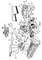
- Figure 1 is a schematic perspective "exploded" view of a combine harvester built according to the modular concept and embodying a first particular combination of specific individual modules,Figure 2 to 5 are views similar to figure 1 but showing different combinations of specific individual modules.
- The terms "forward", "rearward", "left" and "right" used in connection with the combine harvester and/or components thereof are determined with reference to the direction of forward operative travel of this combine harvester but should not be considered as limiting.
- Also, the terms "grain", "straw", and "tailings" are used principally throughout this specification for convenience and it should be understood that these terms equally are not intended to be limiting. Thus "grain" refers to that part of the crop which is threshed and separated from the discardable part of the crop material which is referred to as "straw".
- Incompletely threshed ears are referred to as "tailings".
- With reference to the figures, the combine harvester comprises the so-called base unit which basically consists of the entire machine less the
header 1 and the straw elevator 6. The header as shown in the drawings is a so-called grainheader, but could be of any other type such as e.g. a corn header or a windrow pick-up attachment, depending on the type of crop and the condition of the crop to be harvested. Theheader 1 therefore conventionally forms a separate module and is detachably mounted on the forward end of the straw elevator 6. Theheader 1 shown in the drawings comprises aheader trough 2 with cutter means (not shown) at its forward end and aheader auger 3 rearwardly thereof. Theheader auger 3 is arranged to transversely consolidate harvested crop material and to convey this crop material through anoutlet 4 disposed centrally in the rear wall of theheader 1 and which communicates with the straw elevator 6. Theheader 1 conventionally further also comprises areel 5 which is a further sub-assembly or module which is detachably mounted on theheader trough 2 at a position above and partially forwardly of the cutter means and which may be interchangeable with a reel of a different type. - As is generally known in the art, the elevator 6 is formed as another sub-assembly which can easily be mounted at the forward end of the base unit generally at the threshing portion thereof and which can be adjusted angularly relative to the base unit by means of hydraulic lifting cylinders (not shown). The straw elevator 6 comprises a box-like framework of generally rectangular cross-section and houses conveyor means (not shown) which, in use, are operable to convey crop material received from the
header 1 to the threshingmeans 7. - With reference to figures 1 to 5, the base unit of the combine harvester mainly comprises threshing means 7, separating means 8 and cleaning means 9. The
threshing means 7 are operable to thresh crop material fed thereto, i.e. the crop material (which may be wheat, corn, rice, soybeans, rye, grass seed, barley, oats or other similar crops) is rubbed and beaten, whereby the grain, seed or the like, is loosened and separated from the straw, stalks, coils or other discardable part of the crop. The separating means 8 receive threshed crop material from the threshingmeans 7 and subject said crop material to a further separating action whereby grain not already separated from the rest of the crop material in the threshingmeans 7 is separated therefrom in said separatingmeans 8. Grain which has been separated from the straw in the threshingmeans 7 and the separatingmeans 8 is conveyed to thecleaning means 9 which is operable to separate chaff and other impurities from the grain on the one hand and to separate unthreshed or incompletely threshed material (known in the art as "tailings") from the clean grain on the other hand. Cleaned grain is then elevated into agraintank 10 and the tailings either are returned to the threshingmeans 7 for a repeat threshing action or are subjected to a renewed threshing action in separate tailings rethresher means whereafter said tailings are recycled through thecleaning means 9. - The base unit further also comprises a
power source 11 which is operatively coupled to the various machine components for driving these components and to combine propulsion means for making the combine harvester mobile. The combine harvester normally comprises a front pair oftraction wheels 12 and a rear pair ofsteerable wheels 13. An operator'sstation 14 often provided within an operator'scab 15 and comprising an operator'sseat 16 and all necessary controls, is provided generally at the forward end of the base unit and at a raised position so as to enable the operator, when positioned on the operator's station, to overview the harvesting operation of theheader 1. The combine harvester further also comprises astrawhood 17 which is attachable to the rear of the machine. The invention is concerned basically, but not exclusively, with the threshing means 7, the separating means 8 and the cleaning means 9 which are provided in modules; said modules being interchangeable with other modules comprising respectively different types of threshing means 7, separating means 8 and cleaning means 9. - With reference to figure 1, a combine harvester is shown; which, as far as the threshing means 7 and the separating means 8 are concerned, is indicated in the art as being "conventional". The cleaning means 9 thereof are not "conventional" as will be explained furtheron.
- Considering first the threshing means 7, it will be seen that these are provided within a threshing
module 20 which is arranged to be detachably mounted on top of acleaning module 50 at the forward end thereof. This threshingmodule 20 is equally well mountable on top of thecleaning module 40 shown in figures 2 to 5. To this end, the threshingmodule 20 has aframework 21 of a width corresponding to the width of thecleaning module framework 51 and comprisesside walls 22 which are attachable to the respective fore-and-aft main beams 52 of thecleaning module 50. The threshing means 7 in the threshingmodule 20 comprise aconventional threshing cylinder 23 which is rotatable around a transverse axis and which is cooperable with a conventional threshing concave 24. This concave 24 extends generally circumferentially around a portion of the threshingcylinder 23 at a small distance therefrom to define a gap therebetween through which, in use, crop material is urged in a generally rearward direction while subjecting said crop material to a threshing action. - The threshing means 7 further also comprise a so-called
straw deflector beater 25 which is rotatably mounted within the threshingmodule 20 in parallel and crop receiving relationship with the threshingcylinder 23 and rearwardly therof. Thebeater 25 is rotatable in the same direction as the threshingcylinder 23 and is cooperable with a stationarydeflector beater grate 26 mounted therebelow. As is generally known in the art, thedeflector beater 25 and associatedgrate 26 are operable to receive threshed crop material from the threshingcylinder 23, to deflect the path of movement thereof and to direct it to a further crop processing component in the machine while subjecting it to a further threshing action. Threshed grain is separated through the threshing concave 24 and thegrate 26 and is allowed to fall onto the cleaning means 9 in thecleaning module 50 therebelow. - The threshing means 7 as described above and comprising the threshing
cylinder 23 and concave 24 together with thedeflector beater 25 and associatedgrate 26 possibly are the simpliest, least expensive and most commonly used threshing means which are known since many decades and which have been fully satisfactory in most circumstances. - The
framework 21 of the threshingmodule 20 is adapted for attaching to the top thereof thegraintank module 10, which, except for the fact that it is also built according to the modular concept, is fully conventional and basically comprises atank body 60, a graintank unloading auger 61 and an unloadingtube 62. Thetank body 60 is adapted to be detachably connected to thesidewalls 22 of the threshingmodule framework 21 which haveupper edges 63 which are shaped to match with saidbody 61. - The
framework 21 of the threshingmodule 20 further also is adapted for detachably coupling thereto at the forward end thereof, on the one hand, the header and thestraw elevator combination 1 to 6 and, on the other hand, the module of the operator'sstation 14, which, as already mentioned, may be completed with the operator'scab module 15. - The modules forming the- grain tank, the operator's station eventually completed with the operator's cab, the header and the straw elevator as used in the combination shown in figure 1 also may be used in other combinations, some of which have been shown in figures 2 to 5, although it also will be appreciated that any one or more of these modules may be interchangeable with modules of a different type. As an example different size
grain tank modules 10 may be available to accommodate the end user's wishes. Also, and as generally known in the art, a range of headers of varying widths is normally available. - Turning now to the separating means 8 shown in figure 1, it will be seen that these are formed by a plurality of
conventional straw walkers 31 which are mounted for generally back-and-forth oscillatory movement in the lengthwise direction of the machine within a separatingmodule 30 including aframework 32. Theframework 32 has the same width as theframework 51 of thecleaning module 50 and theframework 21 of the threshingmodule 20 so that the separatingmodule 30 matches with the threshingmodule 20 and thecleaning module 50. Theside walls 33 of theframework 32 are detachably connectable, on the one hand, to the rear portions of the main beams 52 of thecleaning module 50 at the upper edge thereof and, on the other hand, to the rear edges of theside walls 22 of the threshingmodule 20. - When the separating
module 30 is mounted within the combine harvester, thestraw walkers 31 thereof have their forward ends in crop receiving relationship relative to thestraw deflector beater 23 and associatedgrate 24 and, in use, are operable to convey threshed crop material thereover for ultimate discharge from the machine at the rearward end thereof while subjecting said crop material to a further separating action to separate further grain loosened from the ears but not already separated from the rest of the crop material in the threshing means 7. It will be seen from figure 1 that the foreward ends of thestraw walkers 31 extend forwardly beyond the foreward edges of theframework 32 in a manner to project into the threshingmodule 20 when mounted on the combine harvester. - In operation, separated grain is allowed to fall onto the cleaning means 9 in the
cleaning module 50 for further processing. - The separating means 8 in the form of
straw walkers 31 are simple and rather inexpensive in design and are known in the art already for many decades. The separating capacity thereof is rather limited. Sometimes, this type of separating means is found to be the capacity limiting factor of a combine harvester. Accordingly, there are end users who consider straw walkers to be old fashioned although by many other end users, they are considered to be reliable and to have an advantage over rotary separating means to the extent that straw walkers treat straw more gently than rotary separating means whereby they produce less short straw which in turn results in a more moderate loading of the cleaning means 9. For these reasons, straw walkers may be found to be ideal separating means for brittle straw conditions which prevail in e.g. the Southern part of Europe and provided the capacity requirements are not put too high. Straw walkers also may be considered to be the ideal type of separating means in those circumstances where threshed straw still has an appreciable value to the extent that straw walkers indeed produce better quality straw which furthermore is better baleable with less straw being lost. - The
strawhood module 17 is detachably connectable to the rear of the separatingmodule 30 and theframework 32 further also is adapted to receive thepower source 11 on its upper end. - Turning now to the cleaning module, it should be remarked that the
cleaning module 50 shown in figure 1 is a more sophisticated one while that asimpler cleaning module 40 is shown in the figures 2 to 5. It will be appreciated however that thissimpler cleaning module 40 equally well fits under the threshingmodule 20 and separatingmodule 30 as shown in figure 1 and as already mentioned hereabove. - Considering first the
simpler cleaning module 40 shown in figures 2 to 5, it will be appreciated that it basically comprises amobile framework 41 of rectangular shape supporting the cleaning means 9. Therectangular framework 41 comprises a pair of fore-and-aft extendingmain beams 42 coupled to each other at their forward ends by atransverse wheel axle 43 supporting also at its opposite ends thetraction wheels 12. A transverse rear beam (not shown) completes therectangular framework 41 at the rear end thereof and pivotably supports at its central portion asteering wheel axle 44 which in turn supports at its opposite ends thesteerable wheels 13. As therectangular framework 41 has to carry most of the weight of the combine harvester it is made really strong. Theframework 41 further also supports combine propulsion means (not shown) which are operatively coupled to thetraction wheels 12 to make the combine harvester mobile and which may be either of the mechanical or the hydraulic type. - The cleaning means 9 supported in the
cleaning module 40, basically comprise agrain pan 45, a cleaning shoe with upper and lower cleaning sieves and a cleaningfan 47, as is conventional. Thegrain pan 45 is mounted on theframework 41 for generally back-and-forth oscillatory movement in the longitudinal direction of the machine generally below the threshingmodule 20. Thegrain pan 45 itself is conventional in design and therefore needs no further explanation. Thegrain pan 45 is mounted in threshed grain receiving relationship with the threshing means 7 and the separating means 8 and, in use, is operable to convey this threshed grain to the cleaning shoe which is disposed rearwardly thereof. The cleaning shoe, as already mentioned, normally comprises upper and lower cleaning sieves, only the upper one of which can be seen in the drawings at 46. The upper and lower cleaning sieves equally are arranged to oscillate back-and-forth generally in the longitudinal direction of the machine to convey threshed grain therealong while subjecting it to a cleaning action. Preferably theupper sieve 46 and thegrain pan 45 are oscillated in phase while that the lower sieve is oscillated with a phase difference of 180 degr. relative to theupper sieve 46. - The cleaning
fan 47 is mounted below thegrain pan 45 and is disposed to direct a cleaning air blast through the threshed grain as it passes from thegrain pan 45 to theupper cleaning sieve 46 on the one hand and as it is conveyed along the sieves on the other hand whereby chaff and other impurities are made airborne for discharge from the combine harvester. Tailings are separated from the clean grain for recycling as will be explained furtheron in more details and clean grain is collected at the lower end of the cleaning means 9 whereafter it is conveyed through a clean grain elevator (not shown) to thegrain tank module 10 for temporary storage therein. The clean grain elevator itself also may be in the form of a module which is detachably connectable between thecleaning module 40 and thegrain tank module 10. - The tailings separated in the cleaning means 9 normally are recycled back to the threshing
module 20 through areturn conveyor module 90 for repeated threshing action. Thisreturn conveyor module 90 normally is an auger type conveyor which extends between thecleaning module 40 and the threshingmodule 20 along one side of both of said modules. Thereturn conveyor module 90 is detachably connected at its receiving end to the transversetailings collecting conveyor 91 which equally is of the auger type and which extends beneath the cleaning means 9 and beyond one side thereof. The tailings returnconveyor module 90 is provided with athrower 92 at its discharge end which is adapted to throw tailings transversely across the width of the threshingmodule 20 at a location generally forwardly of the threshingcylinder 23. - Alternatively, the tailings return conveyor module may comprise a separate tailings rethresher means for rethreshing the tailings as they pass through the return conveyor module and in which case, the tailings no longer have to be recycled back to the threshing
module 20. In this case, the tailings return conveyor module has its discharge end positioned at a level slightly above thegrain pan 45 in a manner to recycle rethreshed tailings back through the cleaning means 9 in thecleaning module 40. A tailings rethresher and return conveyor of this type is shown and described in more details in GB-A 2 051 541 the content of which is included in the present disclosure by reference. - When all modules described so far are put together the combine harvester is not yet complete to the extent that drives, shieldings and eventual optional attachments still should be installed. These components have not been shown in the drawings for the sake of clarity of the disclosure.
- The drives, which usually are of the mechanical type such as belt or chain drive transmission, extend alongside the various modules and often overlap two or more modules. Drive transmissions which extend between components of only one module, of course, may be installed during the assembly of this specific module, i.e. prior to the putting together of the vanous modules to form a combine.
- After the installation of the drives, also the shieldings still have to be installed to shield the drives for making the machine safe and for providing its final appearance. These shieldings also often overlap two or more modules.
- Normally a range of optional attachments is available. One such attachment is the straw chopper which is mounted within the
strawhood 17. Such attachments usually are installed only upon delivery of a machine to the end user. - A combine harvester comprising the threshing
module 20 and the separatingmodule 30 as shown in figure 1 and thecleaning module 40 as shown in figures 2 to 5 may be considered as a "standard" or fully "conventional" combine which may be the ideal machine for harvesting in brittle straw conditions on level terrain and where the demand for capacity is moderate and the cost price of the machine is a limiting factor for the end user. - It will be appreciated that the modules may be available in a range of widths so as to enable the manufacturer to offer a range of "conventional" combines. As an example, the separating
module 30 may come with 3, 4, 5 or 6straw walkers 31 and four straw elevator modules 6, four threshingmodules 20 and fourcleaning modules 40 of corresponding widths may come along therewith to match with these separatingmodules 30 of different widths. Along therewith, also a range of engines of course also will be made available. - Coming back to the
cleaning module 40, it is remarked that the cleaning means 9 therein may be more sophisticated than those shown in the figures 2 to 5. It will be appreciated e.g. that between thegrain pan 45 and the cleaning shoe a so-called precleaning sieve and intermediate grain pan may be provided. Also the cleaning fan may be of a different type and e.g. may have two outlets. Such components are shown in GB-A 2 063 037 the disclosure of which is included herein by reference. - All cleaning means described so far are particularly adapted to operate on level terrain. When operated in hilly conditions, the cleaning capacity thereof is greatly reduced and moreover, unacceptable grain losses are likely to occur. As is known in the art, unless special precautions are taken, operation on hillsides always results in an uneven loading of the cleaning means with the lower side thereof being overloaded. This is the reason for the reduced cleaning capacity as well as for the unacceptable grain loss level. For these hilly conditions, the invention proposes to interchange the "standard"
cleaning module 40 with afurther cleaning module 50 which is operable to compensate for the adverse influences on the cleaning function of operation in hilly conditions. - Various approaches have been proposed in this respect. One such approach is shown in
DE 3 332 763 following which the cleaning sieves and the grain pan are arranged to oscillate back-and-forth in a direction which deviates from the longitudinal direction of the machine; this deviation depending on the direction and the degree of the slope of ''1e field on which the combine is operating. The am; lement is such that grain to be cleaned on the grai' an and the sieves is urged in the direction of higher side of the cleaning means in an attempt t 3intain an even loading of the cleaning means ss the transverse width thereof. - Another approach overcome this problem of operation in hilly conditions is shown in GB-
A 2 052 238, the disclosure of which is included herein by reference. The same arrangement is schematically shown in figure 1. Basically, the cleaning means 9, i.e. thegrain pan 45, the cleaning shoe with the sieves therein and the cleaningfan 47, are mounted on a pivot frame (not shown) which itself is mounted for pivotal movement around a fore-and-aft extending pivot axis relative to thecleaning module framework 51. The arrangement is such that, when the harvester is inclined transversely relative to the vertical due to operation on a slope, the pivot frame with the cleaning means thereon is pivoted in the opposite direction to assume a generally horizontal position as seen in the transverse direction of the machine. This leveling is obtained automatically by means of an inclinometer which is arranged to control the actuation of position control means for the pivot frame. This self-leveling of the cleaning means 9 is very effective to the extent that it neu- tralises all adverse influences on the cleaning function of operation in hilly conditions. - As already mentioned, figure 1 shows this arrangement only very schematically. As a matter fact, only the forward
central bearing 53 and the pair ofrearward bearing rollers 54 for movably supporting the pivot frame on thecleaning module framework 51 are shown. It will be appreciated that theframework 51 and more especially the main beams 52 thereof are shaped and dimensioned to accommodate the pivot frame therebetween. Thus thisframework 51 is different from theframework 41 of the "standard"cleaning module 40. However, in any event, theframework 51 has its upper edges dimensioned and shaped so as to match with the threshing and separatingmodules further cleaning module 50 may be identical to the cleaning means 9 in the "standard" orfirst cleaning module 40. - While that in the preferred embodiment of the
further cleaning module 50, thegrainpan 45, the cleaning shoe with both cleaning sieves therein and the cleaningfan 47 all are mounted on the pivot frame for selfleveling operation as a unit, it will be appreciated that it is also possible to make only either one or both cleaning sieves self-leveling. Alternatively sections of the cleaning sieves may be made self- leveling. Following still another alternative, one or both cleaning sieves together with the grain pan may be made self-leveling. It will be evident that in all these alternative arrangements the pivot frame will have to be adapted accordingly. However, in any event the cleaning module framework always matches with the threshingmodule 20 and the separatingmodule 30. - Turning now to figure 2, it will be seen that the threshing
module 27 shown therein is slightly different from themodule 20 shown in figure 1. This second threshingmodule 27 not only comprises the threshingcylinder 23 and associated concave 24 together with thedeflector beater 25 and the associatedgrate 26, but further also comprises a third rotatable element and an associated stationary element. This third rotatable element is arethresher cylinder 28 which extends parallel to the threshingcylinder 23 and thebeater 25 and is rotatable in the same direction. The stationary element is a rethresher concave 29 positioned at a small distance from therethresher cylinder 28 so as to define a gap therebetween for the passage of crop material therethrough. As crop material is passed therethrough, it is subjected to a further threshing and separating action, whereby further grain is separated from the crop material through the rethresher concave 29 and is allowed to fall onto the cleaning means 9. Rethresher means as described hereabove have been shown and described in GB-A 1 318 071, the disclosure of which is included herein by reference and to which is referred for more details. - The various components in the
second threshing module 27 may be proportionally smaller so as to make sure that the discharge ends of the threshing means 7 in both the first and thesecond threshing module second threshing module 27 is interchangeable with thefirst threshing module 20 and matches with thefirst separating module 30 already described herebefore and shown in figure 1. Theframeworks 21 of both threshingmodules - Alternatively and indeed also preferably and as shown in figure 2, the threshing
cylinder 23 and concave 24 together with thebeater 25 andgrate 26, as used in thesecond threshing module 27, may be identical to the corresponding components of thefirst threshing module 20, whereby the location of the discharge end of the threshing means in thesecond threshing module 27, i.e. of the rethresher means 28, 29, is different from the location of the discharge end of the threshing means 7 in thefirst threshing module 20, i.e. of thebeater 25 andgrate 26. Also preferably theframeworks 21 in both modules have the same length and indeed even may be identical, whereby, in the combination of thefirst threshing module 20, cover plates are needed to close off the mounting holes in theside walls 22 for the rethresher shaft and the rethresher concave mounting pins. - It will be appreciated that the
first separating module 30 shown in figure 1 will not match with the foregoing version of thesecond threshing module 27 to the extent that, when both modules were assembled on either a first or further cleaningmodule 40, respectively 50, thestraw walkers 31 thereof would interfere with the rethresher means 28-29. - Accordingly, a
second separating module 34 withshorter straw walkers 35 is available for combining with the aforementioned version of thesecond threshing module 27. When both thesecond threshing module 27 and thesecond separating module 34 are mounted on any one of thecleaning modules straw walkers 35 have their forward ends positioned in crop receiving relationship to the discharge end of the rethresher means 28, 29. When comparing the separatingmodules straw walkers 31 of thefirst separating module 30 have six "steps" while that thestraw walkers 35 of thesecond separating module 34 have only five "steps". It will also be noted that thestraw walkers 35 of thesecond separating module 34 do not extend forwardly into thesecond threshing module 27. Instead the rethresher means 28-29 of thesecond threshing module 27 extend over a short distance within thesecond separating module 34. - Again the
framework 36 of thesecond separating module 34 has the same width as theframeworks second threshing modules second cleaning modules sidewalls 37 thereof to be detachably connected to theside walls 22 on the one hand and themain beams 42 or 52 on the other hand. - According to still another alternative approach the threshing
cylinders 23 andconcaves 24 together with thebeaters 25 and grates 26 in both the first andsecond threshing modules first threshing module 20 is correspondingly shorter than the framework of thesecond threshing module 27; the arrangement being such that the threshing means 7 in bothmodules second separating module 34 is positionable in any one of two positions on thecleaning module 40/50, thissecond separating module 34 withshorter straw walkers 35 can be made to match with as well thefirst threshing module 20 as thesecond threshing module 27. - The use of the
second threshing module 27 including the rethresher means 28, 29 in combination with a separatingmodule 34 of the straw walker type is recommended where the straw walkers of the "standard" combination are felt as the capacity limiting factor of the combine harvester and where there is a demand for a higher capacity. The rethresher means 28-29 indeed improve to a great extent the separating capacity of the threshing and separating means 7-8. This may be to the detriment of the straw quality as said rethresher means 28-29 are somewhat more aggressive, which is why the rethresher means 28-29 should be recommended only when the straw to be harvested is somewhat tougher i.e. less brittle. In any event, the combination with rethresher means 28-29 is still very much less aggressive to the straw than the rotary separating means known today. Furthermore, as far as cost is concerned, the combination including the rethresher means 28-29 still may be considered to belong to the lower range. - Turning now to figure 3, it will be noticed that the combination shown therein is basically the same as the combination shown in figure 2, except for the fact that the
second separating module 34 of figure 2 is replaced by athird separating module 65 which is of the rotary type. The rotary separating means 8 therein are of the single flow type and as such are of an offset design with aninlet 66 at one end for communication with the rethresher means 28-29 and an outlet (not shown) at the other end. These rotary separating means 8 comprise a separatingrotor 67 surrounded by a separating housing including separating concaves (not shown). These separating means 8 again extend parallel to the rotatable components in the threshingmodule 27 and therotor 67 equally is rotated in the same direction as said threshing components. - The separating
rotor 67 and associated separator housing have a width which exceeds the width of the threshingmodule 27 and thecleaning modules framework 68 of thisthird separating module 65 is such that, when mounted in a combine harvester, the separating means 8 have one end generally aligned with the corresponding sides of the threshingmodule 27 and of thecleaning module module 27 and thecleaning module - In operation, crop material is received from the rethresher means 28, 29 through the
inlet 66 and is conveyed spirally around therotor 67 towards the offset outlet for discharge therethrough while subjecting said crop material to an aggressive separating action. Grain separated in theportion 69 of the separating means 8 overlying thecleaning module cleaning module module 95 which has a dual function to the extent that it also is operable to recycle half of the tailings separated in the cleaning means 9 back to thegrain pan 45. With respect to this tailings recycling function, themodule 95 is very similar to theconveyor module 90 already described and which in the combination presently under consideration is also being used. Indeed, thetailings collecting conveyor 94 in this combination is operable to convey half of the tailings separated in thecleaning module first conveyor module 90 including, as already described, a special tailings rethresher, is provided at one side of thecleaning module grain pan 45. Thefurther conveyor module 95 is provided at the other side of thecleaning module further conveyor module 95 is connected to the corresponding end of thetailings collecting conveyor 94 and also has at its discharge end a thrower means 96 which is arranged to spread recycled material transversely across the width of thegrain pan 45. - The
further conveyor module 95 also has a receivingtrough 97 intermediate its ends and which is coupled to the underside of that portion of the separating means 8 which extend beyond the corresponding side of thecleaning module grain pan 45 for subjecting it to a cleaning action. A conveyor module of this type is shown in more details in GB-A 2 051 541, the disclosure of which is included herein by reference. - The
straw hood 17 which matches with thethird separating module 65 is somewhat different from thestraw hood 17 which matches with the straw walkertype separating modules - The combination illustrated in figure 3 forms a so-called "rotary" combine and is particularly attractive when the separating
module 65 is combined with relatively narrow threshing and cleaningmodules - Turning now to figure 4, it will be noticed that, in comparison with figure 3, basically only the
third separating module 65 has been replaced by afourth separating module 75 which again is of the rotary type. Again, a separatingrotor 76 is provided which extends parallel to therethresher cylinder 28 in the threshingmodule 27 and which is rotatable in the same direction as thisrethresher cylinder 28. The separatingrotor 76 again is mounted within a separating housing comprising separatingconcaves 77. Again the separating means 8 have a greater width than the threshingmodule 27 and thecleaning module - However, in this combination the separating means 8 are fully symmetrical relative to the fore-and-aft vertical plane of symmetry of the combine harvester. In other words, the threshing
module 27 and the separatingmodule 75 have a common fore-and-aft vertical plane of symmetry. Accordingly, the separatingmodule 75 extends an equal length beyond each side of the threshingmodule 27 and thecleaning module framework 78 nevertheless is dimensioned and positioned so as to be detachably connectable to theside walls 22 of the threshingmodule 27 and to themain beams 42, 52 of thecleaning module - The separating housing has a central
forwardly facing inlet 79 of substantially the same width as the threshingmodule 27 and which is positioned to communicate therewith. The layer of crop material is received from the rethresher means 28-29 through theinlet 79 whereafter it is divided in two generally equally sized halves by layer dividing means (not shown) provided generally at or proximate to the fore-and-aft plane of symmetry. The separating means 8 further are operable spirally to convey said halves in opposite directions around therotor 76 towards its opposite ends for ultimate discharge through outlets (not shown) at these ends. During these spiral movements through the separating means 8, the crop material is subjected to an aggressive separating action. - Grain separated in the central portion of the separating
module 75 is allowed to fall directly to thecleaning module module 75 extending beyond the respective opposite sides of thecleaning module grain pan 45 by dualpurpose conveyor modules 95 identical to theconveyor module 95 already described in the combination according to figure 3 and which thus not only convey said separated grain to thegrain pan 45 but furthermore also recycle tailings in the cleaning means 9. Onesuch conveyor module 95 is provided on each side of thecleaning module cleaning module tailings collecting conveyor 94 which conveys half of the tailings in one direction and the other half in the other direction. As already indicated, further details of conveyor means similar to theconveyor modules 95 can be taken from GB-A 2 051 541, the disclosure of which is included herein by reference. - The combination of the threshing means 7 and the separating means 8 as used in the combination of figure 4 equally has been shown and described in more details in GB-
A 2 063 039, the disclosure of which equally is included herein by reference. - The fourth separating means 75 described hereabove preferably, though not exclusively, are combined with relatively wide threshing and cleaning
modules - Returning once more to the combinations illustrated in both figures 3 and 4, it will be appreciated that the threshing modules therein preferably are of the type including the
rethresher cylinder 28 and concave 29, i.e. the threshingmodule 27 although it also will be appreciated that the separatingmodules module 20. - Turning now finally to figure 5, it will be noticed that the various threshing and separating
module single module 80 comprising combined threshing and separating means 7, 8 of the axial flow type. Theframework 81 thereof again has a width which corresponds to the width of thecleaning module framework 81 further also is adapted to support at its upper end thegrain tank module 10 and rearwardly thereof thepower source 11. The operator'sstation module 14 and the straw elevator andheader combination 6, 1 are coupled to the forward end of this combined threshing and separatingmodule 80 and thestraw hood 17, which again may be of a different shape and dimension, is attachable to the rear end thereof. - The threshing and separating means 7-8 comprise at least one
rotor 82 which is rotatably mounted within a corresponding housing including at least one threshing concave 83 and one separating concave 84. The at least one threshing and separatingrotor 82 is rotatable around a generally fore-and-aft extending axis and comprises a threshingsection 85 forwardly of aseparating section 86. Therotor 82 further also comprises afeeder section 87 forwardly of the threshingsection 85 for receiving the layer of crop material from the straw elevator 6 and for changing it's path of movement from a generally rectilinear path in the straw elevator into a generally spiral path in the threshing and separating means 7-8 and extending therealong from front to rear. As crop material is conveyed spirally through the threshing and separating means, it is subjected to an aggressive threshing and separating action. - Preferably two threshing and separating
rotors 82 are provided in corresponding housings in parallel relationship relative to each other. Thefeeder sections 87 in this case, are operable to divide the crop layer received from the straw elevator 6 in two substantially equally sized halves, one of which spirally is conveyed around onerotor 82 and the other one of which spirally is conveyed around theother rotor 82. - Generally at the rear end of the
rotors 82, adischarge beater 88 and correspondinggrate 89 are provided; thebeater 88 being rotatable around a transversely extending axis. The discharge beater and grate 88-89, in operation, receive threshed crop material (straw) from therotors 82 and discharge it rearwardly through thestrawhood 17. As this crop material is passed across thebeater grate 89 it is subjected still to a final separating action. - Grain separated through the threshing and separating
concaves 83, 84 and through thebeater grate 89 is allowed to fall directly to thecleaning module - As the combined threshing and separating
module 80 has the same width as thecleaning module conveyor module 95 of the type as described with reference to e.g. figure 4 for conveying separated grain to the cleaning means 9. For recycling tailings separated in the cleaning means 9 aconveyor module 90 of the type as described with reference to e.g. figure 1 is provided. - A combine harvester embodying the combined threshing and separating means as used in the combination according to figure 5 is shown and described in GB-
A 1 399 601, the disclosure of which is included herein by reference. - The combination as shown in figure 5 typically is a high capacity rotary combine, which is particularly appealing for use in dry crop conditions, which is more "straw friendly" than the rotary combine illustrated in figure 4 and which probably produces the best grain sample (i.e. minimal percentage of damaged grain) in the business which, in certain areas is a very important criterion. This combination further also is a typical high capacity corn combine.
- In general, it thus will be appreciated that the invention enables the manufacturer to offer a wider range of combines with a relatively small number of parts and at an "acceptable cost. Thus, greater flexibility is provided to meet the customer's demand. Also the invention facilitates the application of the principles of "model mix " by the manufacturer during assembly. Fewer spare parts have to be stocked at the manufacturer's and dealer's levels and less dealer training is required.
- It will be understood that changes in the details, materials, steps and arrangement of parts, which have been described and illustrated to explain the nature of the invention, will occur to and may be made by those skilled in the art upon a reading of this disclosure within the scope of the invention. The foregoing description illustrates several embodiments of the invention; however, concepts, as based upon the description may be employed in other embodiments without departing from the scope of the invention.
Claims (29)
said further threshing module (27) comprising further threshing means (7) including:
said further return conveyor module (95) being operable to convey to the grain pan (45) both: - rethreshed tailings received from the cleaning shoe and
said return conveyor modules (75) being operable to convey to the grain pan (45) both:
Priority Applications (6)
| Application Number | Priority Date | Filing Date | Title |
|---|---|---|---|
| DE8686201152T DE3674001D1 (en) | 1986-07-01 | 1986-07-01 | HARVESTER. |
| EP86201152A EP0250654B1 (en) | 1986-07-01 | 1986-07-01 | Combine harvester |
| US07/068,082 US4846198A (en) | 1986-07-01 | 1987-06-29 | Modular combine harvester |
| BR8703328A BR8703328A (en) | 1986-07-01 | 1987-06-30 | DEBULATOR HARVESTER |
| AU74944/87A AU606828B2 (en) | 1986-07-01 | 1987-06-30 | Modular combine harvester |
| CA000540935A CA1288018C (en) | 1986-07-01 | 1987-06-30 | Modular combine harvester |
Applications Claiming Priority (1)
| Application Number | Priority Date | Filing Date | Title |
|---|---|---|---|
| EP86201152A EP0250654B1 (en) | 1986-07-01 | 1986-07-01 | Combine harvester |
Publications (2)
| Publication Number | Publication Date |
|---|---|
| EP0250654A1 EP0250654A1 (en) | 1988-01-07 |
| EP0250654B1 true EP0250654B1 (en) | 1990-09-05 |
Family
ID=8195757
Family Applications (1)
| Application Number | Title | Priority Date | Filing Date |
|---|---|---|---|
| EP86201152A Expired EP0250654B1 (en) | 1986-07-01 | 1986-07-01 | Combine harvester |
Country Status (6)
| Country | Link |
|---|---|
| US (1) | US4846198A (en) |
| EP (1) | EP0250654B1 (en) |
| AU (1) | AU606828B2 (en) |
| BR (1) | BR8703328A (en) |
| CA (1) | CA1288018C (en) |
| DE (1) | DE3674001D1 (en) |
Families Citing this family (46)
| Publication number | Priority date | Publication date | Assignee | Title |
|---|---|---|---|---|
| DE3533773C2 (en) * | 1985-09-21 | 1993-09-30 | Claas Ohg | Self-propelled forage harvester |
| DE3917605A1 (en) * | 1989-05-31 | 1990-12-06 | Claas Ohg | HARVESTER |
| US5203738A (en) * | 1991-08-01 | 1993-04-20 | American Cyanamid Company | Combine for rapid head change |
| US5354236A (en) * | 1993-04-05 | 1994-10-11 | Charles Dee | Method of converting corn picker/husker to reduce kernel loss and damage |
| GB9407578D0 (en) * | 1994-04-13 | 1994-06-08 | Reekie Mfg Ltd | Chassis system |
| US5499948A (en) * | 1994-09-01 | 1996-03-19 | Deere & Company | Modular threshing assembly for a combine |
| DE19725304A1 (en) * | 1997-06-14 | 1998-12-17 | Same Deutz Fahr Spa | Agricultural harvester |
| GB2328601A (en) * | 1997-08-29 | 1999-03-03 | Ford New Holland Nv | Cleaning means for a combine harvester |
| US6148593A (en) * | 1998-06-17 | 2000-11-21 | New Holland North America, Inc. | Multifunctional handle for controlling an agricultural combine |
| US6125617A (en) * | 1998-09-15 | 2000-10-03 | Gehl Company | Cut crop processing mechanism for a forage harvester incorporating a pivotable auger |
| US6116008A (en) * | 1999-04-01 | 2000-09-12 | New Holland North America, Inc. | Pivoting faceplate for a feederhouse on an agricultural combine |
| EP1044597B1 (en) | 1999-04-12 | 2003-07-02 | CNH Belgium N.V. | Stone impact detection and ejection for a feederhouse on a agricultural combine |
| DE19932285A1 (en) * | 1999-07-10 | 2001-04-26 | Deere & Co | Self-propelled mower and conveyor |
| US6358143B1 (en) | 1999-09-24 | 2002-03-19 | New Holland North America, Inc. | Pivoting grain tank on an agricultural combine |
| US6367234B1 (en) | 1999-09-24 | 2002-04-09 | New Holland North America, Inc. | Concave shaped grain tank on an agricultural combine |
| US6247295B1 (en) | 1999-10-28 | 2001-06-19 | New Holland North America, Inc. | Hydro-mechanical transmission system for an agricultural combine |
| US6267198B1 (en) | 1999-12-23 | 2001-07-31 | New Holland North America, Inc. | Offset kingpin for a rear steering axle on an agricultural combine |
| US6729951B2 (en) * | 2002-03-28 | 2004-05-04 | Bechtel Bwxt Idaho, Llc | Method and apparatus for selectively harvesting multiple components of a plant material |
| US6984171B2 (en) * | 2002-07-19 | 2006-01-10 | Cnh America Llc | Hydro-mechanical threshing rotor control system for an agricultural combine |
| US6651418B1 (en) * | 2002-07-19 | 2003-11-25 | New Holland North America, Inc. | Modular pickup, stuffer, and rotor |
| GB0427283D0 (en) * | 2004-12-14 | 2005-01-12 | Eyre Robert J | Modular combine harvesting machines |
| US20060277883A1 (en) * | 2005-06-10 | 2006-12-14 | Berger John G | Acoustic stone detection for a feederhouse on an agricultural combine |
| US7670219B2 (en) | 2006-12-13 | 2010-03-02 | Cnh America Llc | Integrated axle and cleaning fan wrapper for an agricultural harvesting machine |
| US7993187B2 (en) * | 2007-05-23 | 2011-08-09 | Cnh America Llc | Foreign object detection and removal system for a combine harvester |
| US7654892B2 (en) * | 2007-11-29 | 2010-02-02 | Deere & Company | Tailings re-thresher deflector |
| US8146974B2 (en) * | 2009-09-03 | 2012-04-03 | Cnh America Llc | Expandable grain tank for agricultural combines |
| GB201013941D0 (en) * | 2010-08-20 | 2010-10-06 | Agco Int Gmbh | Self-propelled harvesters |
| WO2012115495A2 (en) * | 2011-01-05 | 2012-08-30 | Республиканское Государственное Предприятие "Казахский Национальный Аграрный Университет" Министерства Образования И Науки Республики Казахстан | Combine harvester |
| US9615509B2 (en) | 2011-03-17 | 2017-04-11 | Cnh Industrial America Llc | Harvester grain tank having active conveying system |
| JP5608131B2 (en) * | 2011-05-13 | 2014-10-15 | 株式会社クボタ | Combine |
| JP5603838B2 (en) * | 2011-06-30 | 2014-10-08 | 株式会社クボタ | Combine |
| DE102012106603A1 (en) * | 2012-07-20 | 2014-05-15 | Claas Hungaria Kft. | Series independent attachment for harvesting stemmed crops |
| BE1021163B1 (en) * | 2013-09-19 | 2016-01-15 | Cnh Industrial Belgium Nv | CUTTER WITH HIGH-CLEANING SET-UP. |
| CN104054449A (en) * | 2014-07-07 | 2014-09-24 | 江苏大学 | Tangential-longitudinal axial type grain combine harvesting and bundling duplex operation machine |
| GB2535174B (en) * | 2015-02-10 | 2020-10-21 | Kverneland Group Kerteminde As | Plant processing apparatus |
| CN208462428U (en) | 2015-08-28 | 2019-02-05 | 凯斯纽荷兰(中国)管理有限公司 | agricultural harvester |
| CN106358605B (en) * | 2016-08-29 | 2019-04-02 | 江苏大学 | High-effect crawler type picking up and bundling machine and its bale automatic piling system |
| BR102017005429B1 (en) * | 2017-03-17 | 2022-06-28 | Indústrias Reunidas Colombo Ltda | AGRICULTURAL AUTOMOTIVE |
| WO2019082306A1 (en) * | 2017-10-25 | 2019-05-02 | 株式会社クボタ | Combine |
| WO2019082305A1 (en) | 2017-10-25 | 2019-05-02 | 株式会社クボタ | Combine harvester |
| US10575466B2 (en) * | 2017-11-20 | 2020-03-03 | Deere & Company | Modular mounting system for a cotton harvester |
| CN113316384B (en) * | 2018-12-21 | 2023-04-21 | 帝国咨询信息有限公司 | Automatic grain processing equipment and cargo monitoring and tracking system |
| US12471531B2 (en) | 2019-05-23 | 2025-11-18 | Cnh Industrial America Llc | Modular chassis assembly and system for a sugar cane harvester |
| US11712003B2 (en) * | 2020-06-25 | 2023-08-01 | Square Head Inc. | Harvesting system including modular units |
| DE102020134150B4 (en) | 2020-12-18 | 2022-06-30 | PETKUS Technologie GmbH | Separating device, combine harvester with a separating device and method for separating weed seeds and dead crops from the cleaning waste of a harvesting machine |
| CN115191217B (en) * | 2022-06-21 | 2024-04-05 | 山东省农业机械科学研究院 | A soybean and corn synchronous combine harvester and working method thereof |
Family Cites Families (10)
| Publication number | Priority date | Publication date | Assignee | Title |
|---|---|---|---|---|
| DE1457964A1 (en) * | 1965-02-19 | 1969-04-10 | Deere & Co | Threshing machine subdivided into assemblies, especially combine harvester |
| DE1782012A1 (en) * | 1968-07-06 | 1971-07-01 | Koedel & Boehm Gmbh | Combine harvester that can be assembled from structural units |
| BE736754A (en) * | 1969-07-30 | 1970-01-30 | VERBETERINGEN AAN MAAIDORSERS | |
| BE788802A (en) * | 1971-07-06 | 1973-01-02 | Clayson Nv | IMPROVEMENTS TO COMBINES. |
| GB1544188A (en) * | 1976-05-11 | 1979-04-11 | Clayson Nv | Combine harvesters |
| US4202154A (en) * | 1976-08-11 | 1980-05-13 | Sperry Rand Corporation | Crop header for a crop harvesting machine having a crop consolidating component which detachably mounts a plurality of interchangeable crop gathering components |
| US4344443A (en) * | 1979-07-04 | 1982-08-17 | Sperry Corporation | Cleaning apparatus of combine harvesters |
| GB2051541B (en) * | 1979-07-06 | 1983-01-26 | Sperry Nv | Combine harvesters |
| GB2063037B (en) * | 1979-11-14 | 1983-05-18 | Sperry Nv | Combine harvesters |
| DE3332763A1 (en) * | 1983-09-10 | 1985-03-28 | Claas Ohg, 4834 Harsewinkel | DEVICE FOR EVEN DISTRIBUTION OF GOODS IN SELF-DRIVING COMBINES |
-
1986
- 1986-07-01 DE DE8686201152T patent/DE3674001D1/en not_active Expired - Lifetime
- 1986-07-01 EP EP86201152A patent/EP0250654B1/en not_active Expired
-
1987
- 1987-06-29 US US07/068,082 patent/US4846198A/en not_active Expired - Fee Related
- 1987-06-30 BR BR8703328A patent/BR8703328A/en not_active IP Right Cessation
- 1987-06-30 CA CA000540935A patent/CA1288018C/en not_active Expired - Lifetime
- 1987-06-30 AU AU74944/87A patent/AU606828B2/en not_active Ceased
Also Published As
| Publication number | Publication date |
|---|---|
| BR8703328A (en) | 1988-03-15 |
| CA1288018C (en) | 1991-08-27 |
| DE3674001D1 (en) | 1990-10-11 |
| US4846198A (en) | 1989-07-11 |
| AU606828B2 (en) | 1991-02-14 |
| EP0250654A1 (en) | 1988-01-07 |
| AU7494487A (en) | 1988-01-07 |
Similar Documents
| Publication | Publication Date | Title |
|---|---|---|
| US4846198A (en) | Modular combine harvester | |
| CA1046887A (en) | Straw discharge means of harvesting machines | |
| US3946746A (en) | Harvesting machines | |
| EP1154682B1 (en) | Threshing and separating unit for axial flow combines | |
| EP1964464B1 (en) | Guide vane adjustment for combine harvesters | |
| US3593719A (en) | Combine with three-stage separation | |
| US3669122A (en) | Axial flow combine with a rotary discharge | |
| US4663921A (en) | Combine harvester with header-mounted separator | |
| EP0898875B1 (en) | Cleaning means for a combine harvester | |
| US20040144072A1 (en) | Elevator slats for an agricultural harvesting machine | |
| US4208858A (en) | Isolated pneumatic cleaning system | |
| GB2211061A (en) | Combine harvester | |
| CA1142050A (en) | Combine harvester | |
| EP0117590B1 (en) | Combine harvesters | |
| EP0117587B1 (en) | Combine harvesters | |
| US3940911A (en) | Harvesters | |
| EP0117592B1 (en) | Combine harvesters | |
| EP3275304B1 (en) | Lateral shake mechanism for agricultural harvester cleaner | |
| US4310004A (en) | Combine harvester rethresher | |
| CA1195583A (en) | Combine harvester with modified feeder house | |
| CA1211019A (en) | Combine harvesters | |
| US4149543A (en) | Straw discharge means of harvesting machines | |
| USRE31860E (en) | Harvesting machines | |
| US20240196790A1 (en) | Residue Chopper and Spreader Arrangement | |
| EP3157319A1 (en) | Straw walker arrangement for an agricultural harvester |
Legal Events
| Date | Code | Title | Description |
|---|---|---|---|
| PUAI | Public reference made under article 153(3) epc to a published international application that has entered the european phase |
Free format text: ORIGINAL CODE: 0009012 |
|
| 17P | Request for examination filed |
Effective date: 19860701 |
|
| AK | Designated contracting states |
Kind code of ref document: A1 Designated state(s): DE FR GB IT |
|
| RAP3 | Party data changed (applicant data changed or rights of an application transferred) |
Owner name: FORD NEW HOLLAND N.V. |
|
| 17Q | First examination report despatched |
Effective date: 19880913 |
|
| GRAA | (expected) grant |
Free format text: ORIGINAL CODE: 0009210 |
|
| AK | Designated contracting states |
Kind code of ref document: B1 Designated state(s): DE FR GB IT |
|
| ITF | It: translation for a ep patent filed | ||
| REF | Corresponds to: |
Ref document number: 3674001 Country of ref document: DE Date of ref document: 19901011 |
|
| ET | Fr: translation filed | ||
| PLBE | No opposition filed within time limit |
Free format text: ORIGINAL CODE: 0009261 |
|
| STAA | Information on the status of an ep patent application or granted ep patent |
Free format text: STATUS: NO OPPOSITION FILED WITHIN TIME LIMIT |
|
| ITTA | It: last paid annual fee | ||
| 26N | No opposition filed | ||
| REG | Reference to a national code |
Ref country code: GB Ref legal event code: IF02 |
|
| REG | Reference to a national code |
Ref country code: FR Ref legal event code: CD |
|
| PGFP | Annual fee paid to national office [announced via postgrant information from national office to epo] |
Ref country code: GB Payment date: 20050624 Year of fee payment: 20 |
|
| PG25 | Lapsed in a contracting state [announced via postgrant information from national office to epo] |
Ref country code: IT Free format text: LAPSE BECAUSE OF NON-PAYMENT OF DUE FEES Effective date: 20050701 |
|
| PGFP | Annual fee paid to national office [announced via postgrant information from national office to epo] |
Ref country code: FR Payment date: 20050705 Year of fee payment: 20 |
|
| PGFP | Annual fee paid to national office [announced via postgrant information from national office to epo] |
Ref country code: DE Payment date: 20050711 Year of fee payment: 20 |
|
| PG25 | Lapsed in a contracting state [announced via postgrant information from national office to epo] |
Ref country code: GB Free format text: LAPSE BECAUSE OF EXPIRATION OF PROTECTION Effective date: 20060630 |
|
| REG | Reference to a national code |
Ref country code: GB Ref legal event code: PE20 |