EP0250256B1 - Towel dispenser - Google Patents
Towel dispenser Download PDFInfo
- Publication number
- EP0250256B1 EP0250256B1 EP19870305458 EP87305458A EP0250256B1 EP 0250256 B1 EP0250256 B1 EP 0250256B1 EP 19870305458 EP19870305458 EP 19870305458 EP 87305458 A EP87305458 A EP 87305458A EP 0250256 B1 EP0250256 B1 EP 0250256B1
- Authority
- EP
- European Patent Office
- Prior art keywords
- towel
- cover
- roller
- towel dispenser
- dispenser according
- Prior art date
- Legal status (The legal status is an assumption and is not a legal conclusion. Google has not performed a legal analysis and makes no representation as to the accuracy of the status listed.)
- Expired - Lifetime
Links
Images



Classifications
-
- A—HUMAN NECESSITIES
- A47—FURNITURE; DOMESTIC ARTICLES OR APPLIANCES; COFFEE MILLS; SPICE MILLS; SUCTION CLEANERS IN GENERAL
- A47K—SANITARY EQUIPMENT; ACCESSORIES THEREFOR, e.g. TOILET ACCESSORIES
- A47K10/00—Body-drying implements; Toilet paper; Holders therefor
- A47K10/24—Towel dispensers; Toilet paper dispensers
- A47K10/28—Towel dispensers; Toilet paper dispensers dispensing a clean part and taking-up a soiled part, e.g. using rolls; with dispensers for soap or other detergents; with disinfecting or heating devices
-
- Y—GENERAL TAGGING OF NEW TECHNOLOGICAL DEVELOPMENTS; GENERAL TAGGING OF CROSS-SECTIONAL TECHNOLOGIES SPANNING OVER SEVERAL SECTIONS OF THE IPC; TECHNICAL SUBJECTS COVERED BY FORMER USPC CROSS-REFERENCE ART COLLECTIONS [XRACs] AND DIGESTS
- Y10—TECHNICAL SUBJECTS COVERED BY FORMER USPC
- Y10T—TECHNICAL SUBJECTS COVERED BY FORMER US CLASSIFICATION
- Y10T292/00—Closure fasteners
- Y10T292/08—Bolts
- Y10T292/1043—Swinging
- Y10T292/1075—Operating means
- Y10T292/1078—Closure
-
- Y—GENERAL TAGGING OF NEW TECHNOLOGICAL DEVELOPMENTS; GENERAL TAGGING OF CROSS-SECTIONAL TECHNOLOGIES SPANNING OVER SEVERAL SECTIONS OF THE IPC; TECHNICAL SUBJECTS COVERED BY FORMER USPC CROSS-REFERENCE ART COLLECTIONS [XRACs] AND DIGESTS
- Y10—TECHNICAL SUBJECTS COVERED BY FORMER USPC
- Y10T—TECHNICAL SUBJECTS COVERED BY FORMER US CLASSIFICATION
- Y10T70/00—Locks
- Y10T70/50—Special application
- Y10T70/5093—For closures
- Y10T70/5155—Door
- Y10T70/5199—Swinging door
- Y10T70/5246—Dead bolts
- Y10T70/5296—Single
- Y10T70/5345—Swinging
- Y10T70/5363—Key operable only
Definitions
- the present invention relates to a towel dispenser.
- a towel dispenser which accommodates a roll of towel is known. A user pulls the towel out of the dispenser to a position where it can be used, and the used towel is automatically rolled into the dispenser.
- Such a known towel dispenser includes a body fixed onto the wall or the like, and a towel unit detachably mounted in the body.
- the towel unit is covered with a cover which is mounted on the body in such a manner as to be openable.
- the towel hangs below the body to form a loop, and the user wipes his hands on this towel loop.
- the above-described type of towel dispenser is classified into two types: one in which the towel always forms a loop, and the other in which a taxi roller which moves up and down forms a towel loop only when the towel is used. In either type, the towel is rolled up either upward or downward.
- the towel has a tendency to snake or be wound at a slant. These faults inhibit the rolling up of the towel, or the resultant load applied to the supply roller or winding roller by the rolled towel may break it.
- the cover constituting the front lid must be opened, and the towel must be replaced while the cover is held open with one hand.
- US-A-3 214 226 (Brusen) describes a towel dispenser in which the towel enters and leaves the dispenser housing through narrow slots.
- the housing has an upwardly-opening pivoted front cover.
- DE-A-25 55 977 (Schumm) also shows simple slots for the towel to pass through, and a lockable, upwardly-pivoting front cover with pivot pins at its upper corners and guide slides engaging guide pins projecting from the housing.
- EP-A-59 893 (Steiner Company) shows housing slots and a key-lockable front cover that pivots open around a hinge along its top edge.
- a towel dispenser which reduces the tendency of the towel to snake or slant out of line, which has a front cover which does not have to be held open manually during replacement of the towel, and which is lockable.
- a towel dispenser comprising:
- the preamble of claim 1 is based on DE-A-25 55 977.
- the present invention provides in one of its features a towel dispenser incorporating a pair of guide plates extending in the vertical direction along the towel passageway in the frame of a body at the same spacing as the width of the towel.
- the towel When it is moved up and down, the towel passes between the pair of guide plates so that the sidewise displacement of the towel can be prevented, thereby preventing the towel snaking or becoming inclined and enabling it to be fed on a straight line.
- the dispenses has the cover secured to the upper end portions of right and left side plates of a towel dispenser body as a front lid in such a manner as to be openable; a pin for pivotally supporting the cover, the pin being provided on a tab projecting toward the body from each edge of the upper end portion of the cover; a pivot arm having one end pivotally supported on the outer side of each side plate of the body and another, free end which can be pivoted upward; and a roller provided at the free end of the pivot arm and located at a position where it can be engaged with each tab of the cover through an opening formed on each side plate.
- This arrangement of the towel dispenser cover makes it possible for the cover to be kept open. It provides a large space through which the towel can be replaced, thereby facilitating the towel replacement work.
- means for loching the cover comprise a pivot rod pivotally supported between two side plates of a towel dispenser body at a position where it does not interrupt the feeding of a towel, the pivot rod having arms at two ends thereof which extend forward to form angles, preferably right angles; a pin provided on the inner side of the leading end of each of the arms of the pivot rod, the pin being received in a notch of a tab provided on the inner side of each edge of the lower end portion of the openable cover; and a disk rotatably provided on a outer frame fixed to the outer side of each side plate of the body in such a manner as to cover the side plate, the disk having openings into which the prongs of a key can be engaged.
- the pivot rod having two arms is supported at the lower portion of the body in such a manner as to be able to pivot upward.
- the lower end portion of the openable cover is provided with tabs, each tab having a notch which engages with a pin provided on the leading end of each arm.
- the arms are pivoted by the turning of a key from outside.
- the cover can be locked in normal operations by using this locking mechanism. It may be opened only when the towel is replaced, preventing the theft or damage of the towel.
- the cover can be unlocked by inserting a key into key holes and turning it in either direction. This does not require a complicated operation, and can thereby be done with one hand.
- the cover can be opened and kept open with one hand by a simple operation. It remains open so long as no displacement is applied thereto.
- a towel dispenser body generally designated by reference numeral 1 has a pair of side plates 2 which are disposed in a symmetrical manner.
- the rear edge of each side plate 2 is provided with a bent portion 3 which is bent inwardly in such a manner that it forms a right angle with respect to the side plate.
- a pair of horizontally extending supporting beams 4, 5 connect the upper and lower portions of the bent portions 3 on the inner sides thereof.
- the upper supporting beam 4 is provided with a plurality of through-holes 4a which are formed in the shape of keyholes, while the lower supporting beam 5 is provided with a plurality of slits 5a which are elongated in the horizontal direction and are formed at positions corresponding to those of the through-holes 4a.
- the through-holes 4a or the slits 5a receive hooks or the like (not shown) projecting from the wall surface, to fix the body 1 onto the wall surface.
- connection rod 6 extends between each of the two ends of the upper beam 4 and corresponding ends of the lower beam 5.
- Each connection rod 6 is provided with a guide plate 7 which projects inward and extends in the vertical direction.
- the guide plates guide a towel accommodated in the interior of the body 1 in a manner described later.
- the guide plates 7 are spaced apart from each other at the same spacing as the width of the towel and are located at a position where the towel passes.
- each side plate 2 is provided with an elongated protrusion 8 which protrudes outward, and by means of which a ceiling plate 9 is fixed to the side plates 2.
- the ceiling plate 9 is rectangular in shape, and has downwardly bent portions 9a at two longitudinal edges thereof.
- the bent portions 9a extend from the rear edge of the ceiling plate 9 to the vicinity of the forward edge thereof, and each is provided with a lug 9b which fits onto the inner surface of the associated protrusion 8.
- the lugs 9b which fit onto the inner sides of the protrusions 8 are fixed thereto by means of screws or the like, thus making the ceiling plate 9 form the upper side of the body 1.
- a pivot arm 10 is pivotally supported at one end thereof by a screw 11 on the outer side and in the vicinity of the upper end portion of each of the side plates 2.
- a roller 12 is pivotally supported on the inner side of the forward end portion of each of the pivot arms 10 by means of a pin 13.
- the roller 12 has an annular groove 12a thereon. It is received in an opening 14 formed in the vicinity of the upper end portion of the side plate 2 in such a way that it faces the inside of the side plate 2.
- a spring 16 extends between the free end of each of the pivot arms 10 and a pin 15 projecting from the upper end portion of the side plate 2. The spring 16 urges the pivot arm 10 to pivot clockwise, as viewed in Figs. 6 and 8.
- the opening 14 is elongated in the vertical direction, so that the roller 12 can move in the vertical direction along the whole length of the opening 14.
- a supporting beam 17 connects the lower edges of the side plates 2 at the centers thereof.
- the two ends of the supporting beam 17, which is pressed from a metal plate, have bent portions 17a which bend upward in such a manner that they form right angles with respect to the supporting beam.
- the bent portions 17a fit onto the outer sides of the lower end portions of the side plates 2, and are fixed thereto by means of screws or the like.
- the supporting beam 17 is also provided with a guide rod 17b which extends along the entire length of the forward edge thereof.
- the guide rod 17b has a U-shaped cross-section with its open side facing downward.
- the guide rod 17b receives a linear portion 18a of a pivot rod 18 from below.
- the pivot rod 18 is a round metal bar, and is bent forward at two positions at right angles to form arms 18b at two end portions thereof.
- the two ends of the linear portion 18a are received in notches 2a formed on the lower edges of the side plates 2 in such a manner that the arms 18b are located outside of the side plates 2.
- a bracket 19 is fixed to the inner side of the leading end of each of the arms 18b, and a pin 20 is provided on the inner side of the leading end of each bracket 19.
- Each pin 20 is received by an opening 21 formed in the vicinity of the lower end of the corresponding side plate 2, and on the side thereof which is closer to the forward end, in such a way that the leading end of the pin 20 is located inside of the side plate 2.
- a lug 22 is punched out of each of the side plates 2 above the opening 21, and a spring 23 extends between the lug 22 and the leading end of the bracket 19, so as to urge the bracket 19 clockwise, as viewed in the figure, with respect to the pivot rod 18.
- the towel dispenser body 1 further includes outer frames 24 disposed on the outer sides of the side plates 2.
- Each of the outer frames 24 is formed into substantially the same shape as the side plate 2, with the exception of the width thereof which is slightly smaller than that of the side plate 2.
- each outer frame 24 is provided with a side wall 25 which is formed in such a manner that it projects toward the inside of the device.
- the side wall 25 extends along the entire periphery of the outer frame 24. It has a predetermined width, so that the side plate 24 forms a flat casing as a whole.
- Brackets 26 are provided on the inner surface of each outer frame 24 at positions which are closer to the forward end thereof, and are separated from each other in the vertical direction.
- the brackets 26 each have a screw-hole 26a into which a screw (not shown) is threadedly fitted from an associated through-hole 27 formed in the side plate 2, so as to fix the forward side of the outer frame 24 onto the side plate 2.
- Each side plate 2 is punched outward at positions which are closer to the rear end thereof and which are separated from each other in the vertical direction to form lugs 28.
- the lugs 28 projects from the side plate at right angles.
- the lugs 28 each have a through-hole 28a. They are in contact with the outer side of the rear portion of the side wall 25 of the outer frame 24, and are fixed thereto by threadedly fitting screws 29 into the through-holes 28a and screw-holes 25a formed in the side wall 25.
- each outer frame 24 when each outer frame 24 is fixed onto the outer side of the corresponding side plate 2, it covers the pivot arm 10 and the arm 18b of the pivot rod 18 while maintaining them pivotally, making them invisible.
- a supporting plate 30 is fixed by screws to the underside of each end of the supporting beam 17.
- the forward edge of the supporting plate 30 is provided with an upwardly curved portion 30a which pivotally supports each end of the linear portion 18a of the pivot rod 18 within each end of the guide rod 17b.
- One end of a supporting plate 30 is secured to the lower edge of the bent portion 3 of each side plate 2 by a screw, while the other end of the supporting plate 31 is disposed on the upper side of the corresponding end of the supporting beam 17.
- An inwardly recessed portion 24a is formed on each outer frame 24 at the lower edge and on the side which is closer to the forward edge thereof.
- the recessed portion 24a has a circular opening 24b at one end thereof, through which a locking device 32 comprising a disk 33 and a supporting plate 34 is mounted.
- the disk 33 has a diameter which is slightly larger than that of the circular opening 24b, and is provided with two elongated openings 33a which receive two prongs 35a of a key 35.
- the supporting plate 34 is provided with an opening 34a which has substantially the same diameter as that of the opening 24b, as well as an annular recessed portion 34b which surrounds the opening 34a and rotatably receives the disk 33.
- the supporting plate 34 is secured to the inner side of the recessed portion 24a in such a way that the opening 24b, the disk 33 and the opening 34a are coaxially aligned.
- the arms 18b of the pivot rod 18 are positioned below the openings 33a.
- a cover generally designated by reference numeral 36 is pressed into a shape which ensures that it covers substantially the entire front side of the body 1.
- the upper end portion of the cover 36 is provided with tabs 37 which come into contact with the inner sides of the side plates 2.
- each tab 37 is provided with a pin 38 which is pivotally received in a through-hole 39 formed in the vicinity of the upper edge portion of the corresponding side plate 2.
- each tab 37 is also provided with a notch 37a at a position which is closer to the forward end thereof.
- the notches 37a together receive the forward edge of the ceiling plate 9.
- each tab 37 is provided with a notch 37b which is received in the annular groove 12a formed on each roller 12.
- Each tab 37 also has a gently curved notch 37c formed at the center of the lower edge thereof and at a position which substantially corresponds to that of the notch 37a.
- the notches 37c fit into the annular grooves 12a of the rollers 12 when the cover 36 is closed.
- a tab 40 projects toward the body from the inner side of each edge of the lower end portion of the cover 36 in such a manner that they form right angles with respect to the cover.
- the lower edge of each tab 40 has a notch 40a and a slope 40b extending from the lower edge of the leading end of the tab 40 to the notch 40a.
- the lower edge of the cover 36 is provided with a rectangular notch 36a at the center thereof.
- the body 1 releasably incorporates a towel unit such as that shown in Fig. 9.
- the towel unit 41 has a pair of side plates 42 (one of which is not shown) disposed as two sides of the towel unit.
- the side plates 42 each have an L-shaped guide groove 43 at opposing positions thereon.
- a shaft 44a of a winding core 44 extends rotatably and slidably between the guide grooves 43.
- the side plates 42 rotatably support a winding roller 45 therebetween in the vicinity of the lower end portions of the guide grooves 43.
- the winding roller 45 is rotated by a motor (not shown).
- the winding roller 45 has an irregular surface with which a used towel 46a wound on the the winding shaft 44 makes contact.
- An arcuate cover 47 is disposed between the winding roller 45 and the towel passage to prevent the towel coming into contact with the winding roller 45.
- a towel receptacle 48 is provided between the lower portions of the side plates 42 to receive an unused towel 46.
- the unused towel 46 is drawn out of the towel receptacle 48 toward the front side thereof by a supply roller 49 disposed above and in front of the receptacle 48. After passing below a bottom plate 50 of the towel unit 41, it is led upward by its contact with a guide shaft 51 disposed at the lower rear portion of the towel unit. The towel is then turned downward by a taxi roller 52, to be described later, and is again turned upward by its contact with the outer side of a guide plate 53 before being wound onto the winding core 44.
- the taxi roller 52 can rise and lower freely. It raises the towel, as shown in Fig. 9, when it rises to its elevated position. When the taxi roller 52 lowers, however, the towel forms a loop hanging below the body 1, ready for use.
- the winding roller 45 and supply roller 49 are rotated in synchronization with the rise and fall of the taxi roller 52 which is raised and lowered by pressing a switch (not shown). Further description of the construction of the taxi roller 52 is omitted.
- the towel when raised and lowered by the taxi roller 52, is led between the previously described guide plates 7.
- the prongs 35a of the key 35 are inserted into the openings 33a of each disk 33 from outside the outer frame 24.
- the key 35 is then turned in either direction with the prongs 35a thereof in contact with the arm 18b of the pivot rod 18. This pushes the arm 18b down, as shown in Fig. 4, and pivots the pivot rod 18.
- the towel unit is replaced in this state.
- the towel is raised and lowered by the taxi roller 52, as described above, to form and break a loop. Since it is led between the guide plates 7 while it is being raised and lowered, it is prevented from displacing sideways, and is wound in good order without snaking or becoming inclined.
- the towel dispenser of this embodiment employs the towel unit which is detachably mounted in its body and in which the towel is raised and lowered by the taxi roller.
- it has the same advantages when applied to any type of towel dispenser, including one in which only the towel is detachably mounted in the body and one which does not employ a taxi roller, so long as the towel passageway is provided with the above-described guide plates.
Landscapes
- Health & Medical Sciences (AREA)
- Public Health (AREA)
- Unwinding Webs (AREA)
Description
- The present invention relates to a towel dispenser.
- A towel dispenser which accommodates a roll of towel is known. A user pulls the towel out of the dispenser to a position where it can be used, and the used towel is automatically rolled into the dispenser.
- Such a known towel dispenser includes a body fixed onto the wall or the like, and a towel unit detachably mounted in the body. The towel unit is covered with a cover which is mounted on the body in such a manner as to be openable.
- The towel hangs below the body to form a loop, and the user wipes his hands on this towel loop.
- The above-described type of towel dispenser is classified into two types: one in which the towel always forms a loop, and the other in which a taxi roller which moves up and down forms a towel loop only when the towel is used. In either type, the towel is rolled up either upward or downward.
- In known towel dispensers the towel has a tendency to snake or be wound at a slant. These faults inhibit the rolling up of the towel, or the resultant load applied to the supply roller or winding roller by the rolled towel may break it.
- Furthermore, when the towel is replaced in such a towel dispenser,the cover constituting the front lid must be opened, and the towel must be replaced while the cover is held open with one hand.
- For example, US-A-3 214 226 (Bahnsen) describes a towel dispenser in which the towel enters and leaves the dispenser housing through narrow slots. The housing has an upwardly-opening pivoted front cover. DE-A-25 55 977 (Schumm) also shows simple slots for the towel to pass through, and a lockable, upwardly-pivoting front cover with pivot pins at its upper corners and guide slides engaging guide pins projecting from the housing. EP-A-59 893 (Steiner Company) shows housing slots and a key-lockable front cover that pivots open around a hinge along its top edge.
- In the present invention we seek to provide a towel dispenser which reduces the tendency of the towel to snake or slant out of line, which has a front cover which does not have to be held open manually during replacement of the towel, and which is lockable.
- Accordingly the invention provides a towel dispenser comprising:
- a body having side plates and
- a front cover pivoted to the side plates at upper portions thereof so as to be openable for access to a towel unit in the body, and which can be locked in a closed position; characterised in that
- the body comprises a pair of opposed guide plates extending along the sides of a towel passageway of the dispenser and spaced at the width of the towel passageway to inhibit deviation of a towel therefrom in use;
- a pivot arm is provided pivotably mounted on each side plate, each pivot arm carrying a roller which is movable up and down relative to the side plate, and
- the cover has tabs projecting from its upper part towards the body, the tabs being engageable with the rollers on the pivot arms to support the cover relative to the body when opened.
- The preamble of
claim 1 is based on DE-A-25 55 977. - Accordingly, the present invention provides in one of its features a towel dispenser incorporating a pair of guide plates extending in the vertical direction along the towel passageway in the frame of a body at the same spacing as the width of the towel.
- When it is moved up and down, the towel passes between the pair of guide plates so that the sidewise displacement of the towel can be prevented, thereby preventing the towel snaking or becoming inclined and enabling it to be fed on a straight line.
- In its preferred form the dispenses has the cover secured to the upper end portions of right and left side plates of a towel dispenser body as a front lid in such a manner as to be openable; a pin for pivotally supporting the cover, the pin being provided on a tab projecting toward the body from each edge of the upper end portion of the cover; a pivot arm having one end pivotally supported on the outer side of each side plate of the body and another, free end which can be pivoted upward; and a roller provided at the free end of the pivot arm and located at a position where it can be engaged with each tab of the cover through an opening formed on each side plate.
- This arrangement of the towel dispenser cover makes it possible for the cover to be kept open. It provides a large space through which the towel can be replaced, thereby facilitating the towel replacement work.
- In a preferred embodiment means for loching the cover comprise a pivot rod pivotally supported between two side plates of a towel dispenser body at a position where it does not interrupt the feeding of a towel, the pivot rod having arms at two ends thereof which extend forward to form angles, preferably right angles; a pin provided on the inner side of the leading end of each of the arms of the pivot rod, the pin being received in a notch of a tab provided on the inner side of each edge of the lower end portion of the openable cover; and a disk rotatably provided on a outer frame fixed to the outer side of each side plate of the body in such a manner as to cover the side plate, the disk having openings into which the prongs of a key can be engaged.
- With this feature, the pivot rod having two arms is supported at the lower portion of the body in such a manner as to be able to pivot upward. The lower end portion of the openable cover is provided with tabs, each tab having a notch which engages with a pin provided on the leading end of each arm. The arms are pivoted by the turning of a key from outside.
- In consequence, the cover can be locked in normal operations by using this locking mechanism. It may be opened only when the towel is replaced, preventing the theft or damage of the towel.
- The cover can be unlocked by inserting a key into key holes and turning it in either direction. This does not require a complicated operation, and can thereby be done with one hand.
- The cover can be opened and kept open with one hand by a simple operation. It remains open so long as no displacement is applied thereto.
- Other preferred features of the invention will become clear upon an understanding of the illustrative embodiment about to be described, or will be indicated in the appended claims, and various advantages not referred to therein will occur to one skilled in the art upon employment of the invention in practice.
- In the drawings in which an embodiment of the present invention is illustrated:
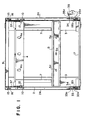
- Fig. 1 is a section taken along the line C-C in Fig. 5;
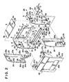
- Fig. 2 is an exploded perspective view of a towel dispenser of the present invention;
- Figs. 3 and 4 are cross-sectional views of an essential part of the towel dispenser, showing the pivot method;
- Fig. 5 is a perspective view of the entire towel dispenser;
- Fig. 6 is a perspective view of a body;
- Fig. 7 is a section taken along the line A-A of Fig. 5;
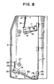
- Fig. 8 is a section taken along the line B-B of Fig. 5; and
- Fig. 9 is a cross-sectional view of the towel dispenser in which a towel unit is incorporated.
- An embodiment of the present invention will be hereinunder described in detail by referring to the accompanying drawings.
- Referring first to Fig. 2 which is an exploded view of a towel dispenser from which a towel unit has been taken out, a towel dispenser body generally designated by
reference numeral 1 has a pair ofside plates 2 which are disposed in a symmetrical manner. The rear edge of eachside plate 2 is provided with abent portion 3 which is bent inwardly in such a manner that it forms a right angle with respect to the side plate. A pair of horizontally extending supportingbeams bent portions 3 on the inner sides thereof. The upper supportingbeam 4 is provided with a plurality of through-holes 4a which are formed in the shape of keyholes, while the lower supportingbeam 5 is provided with a plurality ofslits 5a which are elongated in the horizontal direction and are formed at positions corresponding to those of the through-holes 4a. - The through-
holes 4a or theslits 5a receive hooks or the like (not shown) projecting from the wall surface, to fix thebody 1 onto the wall surface. - A connection rod 6 extends between each of the two ends of the
upper beam 4 and corresponding ends of thelower beam 5. Each connection rod 6 is provided with aguide plate 7 which projects inward and extends in the vertical direction. The guide plates guide a towel accommodated in the interior of thebody 1 in a manner described later. - The
guide plates 7 are spaced apart from each other at the same spacing as the width of the towel and are located at a position where the towel passes. - The upper end portion of each
side plate 2 is provided with anelongated protrusion 8 which protrudes outward, and by means of which aceiling plate 9 is fixed to theside plates 2. - The
ceiling plate 9 is rectangular in shape, and has downwardly bent portions 9a at two longitudinal edges thereof. The bent portions 9a extend from the rear edge of theceiling plate 9 to the vicinity of the forward edge thereof, and each is provided with alug 9b which fits onto the inner surface of the associatedprotrusion 8. - The
lugs 9b which fit onto the inner sides of theprotrusions 8 are fixed thereto by means of screws or the like, thus making theceiling plate 9 form the upper side of thebody 1. - A
pivot arm 10 is pivotally supported at one end thereof by ascrew 11 on the outer side and in the vicinity of the upper end portion of each of theside plates 2. - A
roller 12 is pivotally supported on the inner side of the forward end portion of each of thepivot arms 10 by means of apin 13. Theroller 12 has anannular groove 12a thereon. It is received in anopening 14 formed in the vicinity of the upper end portion of theside plate 2 in such a way that it faces the inside of theside plate 2. - A
spring 16 extends between the free end of each of thepivot arms 10 and apin 15 projecting from the upper end portion of theside plate 2. Thespring 16 urges thepivot arm 10 to pivot clockwise, as viewed in Figs. 6 and 8. - The
opening 14 is elongated in the vertical direction, so that theroller 12 can move in the vertical direction along the whole length of theopening 14. - A supporting
beam 17 connects the lower edges of theside plates 2 at the centers thereof. - The two ends of the supporting
beam 17, which is pressed from a metal plate, have bent portions 17a which bend upward in such a manner that they form right angles with respect to the supporting beam. The bent portions 17a fit onto the outer sides of the lower end portions of theside plates 2, and are fixed thereto by means of screws or the like. - The supporting
beam 17 is also provided with aguide rod 17b which extends along the entire length of the forward edge thereof. Theguide rod 17b has a U-shaped cross-section with its open side facing downward. Theguide rod 17b receives a linear portion 18a of apivot rod 18 from below. Thepivot rod 18 is a round metal bar, and is bent forward at two positions at right angles to formarms 18b at two end portions thereof. - The two ends of the linear portion 18a are received in
notches 2a formed on the lower edges of theside plates 2 in such a manner that thearms 18b are located outside of theside plates 2. - A
bracket 19 is fixed to the inner side of the leading end of each of thearms 18b, and apin 20 is provided on the inner side of the leading end of eachbracket 19. - Each
pin 20 is received by anopening 21 formed in the vicinity of the lower end of thecorresponding side plate 2, and on the side thereof which is closer to the forward end, in such a way that the leading end of thepin 20 is located inside of theside plate 2. - A
lug 22 is punched out of each of theside plates 2 above theopening 21, and aspring 23 extends between thelug 22 and the leading end of thebracket 19, so as to urge thebracket 19 clockwise, as viewed in the figure, with respect to thepivot rod 18. - The
towel dispenser body 1 further includesouter frames 24 disposed on the outer sides of theside plates 2. Each of theouter frames 24 is formed into substantially the same shape as theside plate 2, with the exception of the width thereof which is slightly smaller than that of theside plate 2. - The outer edge of each
outer frame 24 is provided with aside wall 25 which is formed in such a manner that it projects toward the inside of the device. Theside wall 25 extends along the entire periphery of theouter frame 24. It has a predetermined width, so that theside plate 24 forms a flat casing as a whole. -
Brackets 26 are provided on the inner surface of eachouter frame 24 at positions which are closer to the forward end thereof, and are separated from each other in the vertical direction. Thebrackets 26 each have a screw-hole 26a into which a screw (not shown) is threadedly fitted from an associated through-hole 27 formed in theside plate 2, so as to fix the forward side of theouter frame 24 onto theside plate 2. - Each
side plate 2 is punched outward at positions which are closer to the rear end thereof and which are separated from each other in the vertical direction to form lugs 28. Thelugs 28 projects from the side plate at right angles. - The
lugs 28 each have a through-hole 28a. They are in contact with the outer side of the rear portion of theside wall 25 of theouter frame 24, and are fixed thereto by threadedlyfitting screws 29 into the through-holes 28a and screw-holes 25a formed in theside wall 25. - In consequence, when each
outer frame 24 is fixed onto the outer side of thecorresponding side plate 2, it covers thepivot arm 10 and thearm 18b of thepivot rod 18 while maintaining them pivotally, making them invisible. - A supporting
plate 30 is fixed by screws to the underside of each end of the supportingbeam 17. The forward edge of the supportingplate 30 is provided with an upwardlycurved portion 30a which pivotally supports each end of the linear portion 18a of thepivot rod 18 within each end of theguide rod 17b. - One end of a supporting
plate 30 is secured to the lower edge of thebent portion 3 of eachside plate 2 by a screw, while the other end of the supportingplate 31 is disposed on the upper side of the corresponding end of the supportingbeam 17. - An inwardly recessed
portion 24a is formed on eachouter frame 24 at the lower edge and on the side which is closer to the forward edge thereof. The recessedportion 24a has a circular opening 24b at one end thereof, through which a locking device 32 comprising adisk 33 and a supportingplate 34 is mounted. - The
disk 33 has a diameter which is slightly larger than that of the circular opening 24b, and is provided with twoelongated openings 33a which receive twoprongs 35a of a key 35. - The supporting
plate 34 is provided with an opening 34a which has substantially the same diameter as that of the opening 24b, as well as an annular recessedportion 34b which surrounds the opening 34a and rotatably receives thedisk 33. The supportingplate 34 is secured to the inner side of the recessedportion 24a in such a way that the opening 24b, thedisk 33 and the opening 34a are coaxially aligned. - While the
openings 33a are being aligned in the horizontal direction, thearms 18b of thepivot rod 18 are positioned below theopenings 33a. - In consequence, when the
prongs 35a of the key 35 are inserted into one pair of theopenings 33a in this state, theprongs 35 are located above thecorresponding arm 18b, as shown in Fig. 3. When the key 35 is turned so that it becomes upright in this state, theprongs 35a press thearm 18b downward, pivoting thepivot rod 18. - A cover generally designated by
reference numeral 36 is pressed into a shape which ensures that it covers substantially the entire front side of thebody 1. The upper end portion of thecover 36 is provided withtabs 37 which come into contact with the inner sides of theside plates 2. - The outer side of the upper edge portion of each
tab 37 is provided with apin 38 which is pivotally received in a through-hole 39 formed in the vicinity of the upper edge portion of thecorresponding side plate 2. - The upper edge portion of each
tab 37 is also provided with anotch 37a at a position which is closer to the forward end thereof. Thenotches 37a together receive the forward edge of theceiling plate 9. - The leading end portion of each
tab 37 is provided with anotch 37b which is received in theannular groove 12a formed on eachroller 12. - Each
tab 37 also has a gentlycurved notch 37c formed at the center of the lower edge thereof and at a position which substantially corresponds to that of thenotch 37a. Thenotches 37c fit into theannular grooves 12a of therollers 12 when thecover 36 is closed. - A
tab 40 projects toward the body from the inner side of each edge of the lower end portion of thecover 36 in such a manner that they form right angles with respect to the cover. The lower edge of eachtab 40 has anotch 40a and aslope 40b extending from the lower edge of the leading end of thetab 40 to thenotch 40a. - The lower edge of the
cover 36 is provided with arectangular notch 36a at the center thereof. - The
body 1 releasably incorporates a towel unit such as that shown in Fig. 9. - The
towel unit 41 has a pair of side plates 42 (one of which is not shown) disposed as two sides of the towel unit. Theside plates 42 each have an L-shapedguide groove 43 at opposing positions thereon. A shaft 44a of a windingcore 44 extends rotatably and slidably between theguide grooves 43. - The
side plates 42 rotatably support a windingroller 45 therebetween in the vicinity of the lower end portions of theguide grooves 43. The windingroller 45 is rotated by a motor (not shown). - The winding
roller 45 has an irregular surface with which a usedtowel 46a wound on the the windingshaft 44 makes contact. - In consequence, when the winding
roller 45 rotates, the windingcore 44 is rotated through the layers of the usedtowel 46a thereon by friction, winding the used towel further thereon. As the diameter of the wound used towel increases, the support shaft 44a moves upward within theguide grooves 43. - An
arcuate cover 47 is disposed between the windingroller 45 and the towel passage to prevent the towel coming into contact with the windingroller 45. - A
towel receptacle 48 is provided between the lower portions of theside plates 42 to receive anunused towel 46. - The
unused towel 46 is drawn out of thetowel receptacle 48 toward the front side thereof by asupply roller 49 disposed above and in front of thereceptacle 48. After passing below abottom plate 50 of thetowel unit 41, it is led upward by its contact with aguide shaft 51 disposed at the lower rear portion of the towel unit. The towel is then turned downward by ataxi roller 52, to be described later, and is again turned upward by its contact with the outer side of aguide plate 53 before being wound onto the windingcore 44. - The
taxi roller 52 can rise and lower freely. It raises the towel, as shown in Fig. 9, when it rises to its elevated position. When thetaxi roller 52 lowers, however, the towel forms a loop hanging below thebody 1, ready for use. - The winding
roller 45 andsupply roller 49 are rotated in synchronization with the rise and fall of thetaxi roller 52 which is raised and lowered by pressing a switch (not shown). Further description of the construction of thetaxi roller 52 is omitted. - The towel, when raised and lowered by the
taxi roller 52, is led between the previously describedguide plates 7. - The operation of the thus-arranged towel dispenser will be described below.
- While the towel dispenser is ready for use with the
towel unit 41 mounted within thebody 1 and itscover 36 closed, thepins 20 provided at the leading ends of thearms 18b of thepivot rod 18 are fitted into thenotches 40a of thetabs 40. The pins are kept engaged into the notches by the tensions of thesprings 23, and thecover 36 is thereby kept locked and closed. - When it is necessary to replace the towel, the
prongs 35a of the key 35 are inserted into theopenings 33a of eachdisk 33 from outside theouter frame 24. - The key 35 is then turned in either direction with the
prongs 35a thereof in contact with thearm 18b of thepivot rod 18. This pushes thearm 18b down, as shown in Fig. 4, and pivots thepivot rod 18. - This releases the
pins 20 from thenotches 40a of thetabs 40, unlocking thecover 36 and leaving it ready to be opened. - While the
cover 36 is being opened upward, thenotches 37c of thetabs 37 push therollers 12 downward, pivoting thepivot arms 10 downward. Therollers 12 thereby leave thenotches 37c and are received in thenotches 37b after being guided along the slopes formed at the lower edges of thetabs 37. - At this time, the forward edge of the
ceiling plate 9 is received in thenotches 37a, so that thecover 36 can be fully opened, as shown in Fig. 7. - The engagement of the
rollers 12 in thenotches 37b is maintained by the tensions of thesprings 16, and thecover 37 is thereby kept open. - The towel unit is replaced in this state.
- When the
cover 36 is pivoted toward its closed position after the towel unit has been replaced, a large angular moment is applied to therollers 12, pushing thepivot arms 10 and therollers 12 downward against the forces of thesprings 16 and releasing therollers 12 from thenotches 37b. - When the
cover 36 is further pivoted and starts to close, thetabs 40 approach thepins 20 provided at the leading ends of thearms 18b of the pivot rod, and theslopes 40b run onto the upper sides of thepins 20, pushing thearms 18b downward against the forces of thesprings 23. - This causes the
pins 20 to be fitted into thenotches 40a. This engagement of the pins into thenotches 40a is maintained by the tensions of thesprings 23, and the cover is thereby kept locked. - The towel is raised and lowered by the
taxi roller 52, as described above, to form and break a loop. Since it is led between theguide plates 7 while it is being raised and lowered, it is prevented from displacing sideways, and is wound in good order without snaking or becoming inclined. - The towel dispenser of this embodiment employs the towel unit which is detachably mounted in its body and in which the towel is raised and lowered by the taxi roller. However, it has the same advantages when applied to any type of towel dispenser, including one in which only the towel is detachably mounted in the body and one which does not employ a taxi roller, so long as the towel passageway is provided with the above-described guide plates.
Claims (9)
Applications Claiming Priority (6)
| Application Number | Priority Date | Filing Date | Title |
|---|---|---|---|
| JP61144267A JPS62299223A (en) | 1986-06-20 | 1986-06-20 | Front lid opening locking device for towel dispenser |
| JP144268/86 | 1986-06-20 | ||
| JP144267/86 | 1986-06-20 | ||
| JP144266/86 | 1986-06-20 | ||
| JP61144266A JPS62299222A (en) | 1986-06-20 | 1986-06-20 | Lock apparatus in towel dispenser |
| JP61144268A JPS62299221A (en) | 1986-06-20 | 1986-06-20 | Mechanism to prevent towel sway in a towel dispenser |
Publications (3)
| Publication Number | Publication Date |
|---|---|
| EP0250256A2 EP0250256A2 (en) | 1987-12-23 |
| EP0250256A3 EP0250256A3 (en) | 1988-07-20 |
| EP0250256B1 true EP0250256B1 (en) | 1991-01-09 |
Family
ID=27318796
Family Applications (1)
| Application Number | Title | Priority Date | Filing Date |
|---|---|---|---|
| EP19870305458 Expired - Lifetime EP0250256B1 (en) | 1986-06-20 | 1987-06-19 | Towel dispenser |
Country Status (3)
| Country | Link |
|---|---|
| US (1) | US4856854A (en) |
| EP (1) | EP0250256B1 (en) |
| DE (1) | DE3767225D1 (en) |
Families Citing this family (13)
| Publication number | Priority date | Publication date | Assignee | Title |
|---|---|---|---|---|
| DE3840640A1 (en) * | 1988-12-02 | 1990-06-07 | Schumm Erich Kg | TOWEL DISPENSER |
| DE4020707C2 (en) * | 1990-06-29 | 2003-04-30 | Schumm Erich Kg | Towel dispenser |
| JPH11512628A (en) * | 1995-09-26 | 1999-11-02 | キンバリー クラーク ワールドワイド インコーポレイテッド | Stain-resistant toilet dispenser |
| US5845980A (en) * | 1996-11-06 | 1998-12-08 | Haworth, Inc. | Overhead storage cabinet |
| US6059326A (en) * | 1997-06-27 | 2000-05-09 | Kimberly Clark Co | Tamper resistant rotational locking mechanism for an enclosure |
| EP1066784A1 (en) * | 1999-07-05 | 2001-01-10 | Cws International Ag | Method and device for creating a fabric loop in a towel dispenser |
| US6578936B1 (en) * | 2000-11-27 | 2003-06-17 | Pamela Darman | Continuous roll towel dispenser |
| WO2002068785A1 (en) | 2001-02-22 | 2002-09-06 | Krueger International, Inc. | Counterbalanced door system for a storage cabinet |
| US6921141B1 (en) * | 2002-06-13 | 2005-07-26 | Crp Enterprises | Water resistant instrument enclosure |
| CN101257824B (en) * | 2005-09-20 | 2010-12-15 | Sca卫生产品股份公司 | Dispenser |
| AT507804B1 (en) * | 2009-01-16 | 2013-05-15 | Blum Gmbh Julius | WEARING CONSTRUCTION FOR A FURNITURE BASKET |
| AU362368S (en) * | 2014-12-19 | 2015-06-18 | Sca Hygiene Prod Ab | Tissue dispenser |
| WO2025231515A1 (en) * | 2024-05-09 | 2025-11-13 | Hysential Pty Ltd | Locking mechanism for containers |
Family Cites Families (11)
| Publication number | Priority date | Publication date | Assignee | Title |
|---|---|---|---|---|
| US13722A (en) * | 1855-10-30 | butler | ||
| US2899251A (en) * | 1959-08-11 | Towel dispensing cabinets | ||
| US917664A (en) * | 1909-01-05 | 1909-04-06 | Cyril Roy | Door catch and lock. |
| US2367200A (en) * | 1941-01-30 | 1945-01-16 | Jacques Rousso | Towel cabinet |
| US2834645A (en) * | 1951-09-22 | 1958-05-13 | American Linen Supply Co | Towel dispensing apparatus |
| US2817554A (en) * | 1956-09-13 | 1957-12-24 | Stanley Works | Push release latch |
| US3214226A (en) * | 1963-05-10 | 1965-10-26 | Steiner American Corp | Towel dispenser |
| US3684338A (en) * | 1970-12-17 | 1972-08-15 | Steiner American Corp | Compact towel dispenser |
| DE2555977C3 (en) * | 1975-12-12 | 1979-11-29 | Erich 7157 Murrhardt Schumm | Towel dispenser |
| IT1167526B (en) * | 1981-02-27 | 1987-05-13 | Steiner Co Int Sa | APPARATUS TO CONTROL THE WINDING AND UNWINDING OF SPOOLS OF TAPES USED AS TOWELS AND SIMILAR |
| FR2588735B1 (en) * | 1985-10-22 | 1988-08-12 | Alpia Sa | DEVICE FOR BALANCING AND SECURING THE LID OF A VERTICAL PLANE CLASSIFICATION FURNITURE |
-
1987
- 1987-06-19 EP EP19870305458 patent/EP0250256B1/en not_active Expired - Lifetime
- 1987-06-19 US US07/063,629 patent/US4856854A/en not_active Expired - Fee Related
- 1987-06-19 DE DE8787305458T patent/DE3767225D1/en not_active Expired - Lifetime
Also Published As
| Publication number | Publication date |
|---|---|
| EP0250256A3 (en) | 1988-07-20 |
| US4856854A (en) | 1989-08-15 |
| DE3767225D1 (en) | 1991-02-14 |
| EP0250256A2 (en) | 1987-12-23 |
Similar Documents
| Publication | Publication Date | Title |
|---|---|---|
| US4856854A (en) | Towel dispenser | |
| US5813624A (en) | Apparatus for dispensing toilet tissue from rolls | |
| CA2665143C (en) | Dispenser that automatically transfers rolls of absorbent material, method of reloading same, and rolls of absorbent material for use in same | |
| US4363454A (en) | Tissue roll storage and dispenser apparatus | |
| US6983512B2 (en) | Movable door mounting assembly with trolley locking structure | |
| US4944466A (en) | Flexible sheet material dispenser with automatic roll transferring mechanism | |
| US5265816A (en) | Double roll tissue dispenser with sliding door | |
| US4034924A (en) | Apparatus for dispensing and holding tissue rolls | |
| US7866593B2 (en) | Two roll drop front toilet tissue dispenser | |
| US4856724A (en) | Flexible sheet material dispenser with automatic roll transferring mechanism | |
| WO1996024548A1 (en) | Flexible sheet material dispenser with automatic roll transferring mechanism | |
| KR19980080124A (en) | Card Distribution Cassette | |
| US4475580A (en) | Mechanism for a roller blind | |
| AU2005227711B2 (en) | Retaining end piece for a roll of wiping material that is disposed on a wiping material dispensing device | |
| JP3503114B2 (en) | Interlock mechanism | |
| EP1002725B1 (en) | A device for automatically receiving an umbrella in a bag | |
| US4222532A (en) | Roll holder | |
| US4916862A (en) | Ceiling access panel | |
| EP0083151B1 (en) | Frame for film transparency | |
| JP4067421B2 (en) | Separate slot machine | |
| GB2286818A (en) | Liquid dispenser head | |
| KR100982260B1 (en) | Internet refrigerator | |
| EP0461732B1 (en) | Dispenser for multiple rolls of sheet material | |
| KR20050059881A (en) | Communication pad mounting structure for internet refrigerator | |
| JPH1018676A (en) | Door set |
Legal Events
| Date | Code | Title | Description |
|---|---|---|---|
| PUAI | Public reference made under article 153(3) epc to a published international application that has entered the european phase |
Free format text: ORIGINAL CODE: 0009012 |
|
| AK | Designated contracting states |
Kind code of ref document: A2 Designated state(s): CH DE FR GB IT LI NL |
|
| PUAL | Search report despatched |
Free format text: ORIGINAL CODE: 0009013 |
|
| AK | Designated contracting states |
Kind code of ref document: A3 Designated state(s): CH DE FR GB IT LI NL |
|
| 17P | Request for examination filed |
Effective date: 19881221 |
|
| 17Q | First examination report despatched |
Effective date: 19891218 |
|
| GRAA | (expected) grant |
Free format text: ORIGINAL CODE: 0009210 |
|
| AK | Designated contracting states |
Kind code of ref document: B1 Designated state(s): CH DE FR GB IT LI NL |
|
| REF | Corresponds to: |
Ref document number: 3767225 Country of ref document: DE Date of ref document: 19910214 |
|
| ITF | It: translation for a ep patent filed | ||
| ET | Fr: translation filed | ||
| PLBE | No opposition filed within time limit |
Free format text: ORIGINAL CODE: 0009261 |
|
| STAA | Information on the status of an ep patent application or granted ep patent |
Free format text: STATUS: NO OPPOSITION FILED WITHIN TIME LIMIT |
|
| 26N | No opposition filed | ||
| PGFP | Annual fee paid to national office [announced via postgrant information from national office to epo] |
Ref country code: GB Payment date: 19940613 Year of fee payment: 8 |
|
| PGFP | Annual fee paid to national office [announced via postgrant information from national office to epo] |
Ref country code: FR Payment date: 19940617 Year of fee payment: 8 |
|
| PGFP | Annual fee paid to national office [announced via postgrant information from national office to epo] |
Ref country code: DE Payment date: 19940621 Year of fee payment: 8 |
|
| PGFP | Annual fee paid to national office [announced via postgrant information from national office to epo] |
Ref country code: CH Payment date: 19940623 Year of fee payment: 8 |
|
| PGFP | Annual fee paid to national office [announced via postgrant information from national office to epo] |
Ref country code: NL Payment date: 19940630 Year of fee payment: 8 |
|
| PG25 | Lapsed in a contracting state [announced via postgrant information from national office to epo] |
Ref country code: GB Effective date: 19950619 |
|
| PG25 | Lapsed in a contracting state [announced via postgrant information from national office to epo] |
Ref country code: LI Effective date: 19950630 Ref country code: CH Effective date: 19950630 |
|
| PG25 | Lapsed in a contracting state [announced via postgrant information from national office to epo] |
Ref country code: NL Effective date: 19960101 |
|
| GBPC | Gb: european patent ceased through non-payment of renewal fee |
Effective date: 19950619 |
|
| PG25 | Lapsed in a contracting state [announced via postgrant information from national office to epo] |
Ref country code: FR Effective date: 19960229 |
|
| REG | Reference to a national code |
Ref country code: CH Ref legal event code: PL |
|
| NLV4 | Nl: lapsed or anulled due to non-payment of the annual fee |
Effective date: 19960101 |
|
| PG25 | Lapsed in a contracting state [announced via postgrant information from national office to epo] |
Ref country code: DE Effective date: 19960301 |
|
| REG | Reference to a national code |
Ref country code: FR Ref legal event code: ST |
|
| PG25 | Lapsed in a contracting state [announced via postgrant information from national office to epo] |
Ref country code: IT Free format text: LAPSE BECAUSE OF NON-PAYMENT OF DUE FEES;WARNING: LAPSES OF ITALIAN PATENTS WITH EFFECTIVE DATE BEFORE 2007 MAY HAVE OCCURRED AT ANY TIME BEFORE 2007. THE CORRECT EFFECTIVE DATE MAY BE DIFFERENT FROM THE ONE RECORDED. Effective date: 20050619 |