EP0250140A2 - Flugverwaltungssystem - Google Patents
Flugverwaltungssystem Download PDFInfo
- Publication number
- EP0250140A2 EP0250140A2 EP87305051A EP87305051A EP0250140A2 EP 0250140 A2 EP0250140 A2 EP 0250140A2 EP 87305051 A EP87305051 A EP 87305051A EP 87305051 A EP87305051 A EP 87305051A EP 0250140 A2 EP0250140 A2 EP 0250140A2
- Authority
- EP
- European Patent Office
- Prior art keywords
- signal
- arrival time
- cost
- function
- flight
- Prior art date
- Legal status (The legal status is an assumption and is not a legal conclusion. Google has not performed a legal analysis and makes no representation as to the accuracy of the status listed.)
- Granted
Links
- 239000000446 fuel Substances 0.000 claims description 19
- 238000000034 method Methods 0.000 claims description 14
- 230000001133 acceleration Effects 0.000 claims description 11
- 230000003247 decreasing effect Effects 0.000 claims description 8
- 230000004913 activation Effects 0.000 claims 2
- 230000003213 activating effect Effects 0.000 claims 1
- 238000010586 diagram Methods 0.000 description 10
- 230000004044 response Effects 0.000 description 5
- 230000008859 change Effects 0.000 description 3
- 230000000694 effects Effects 0.000 description 3
- 238000004088 simulation Methods 0.000 description 3
- 230000010006 flight Effects 0.000 description 2
- RZVHIXYEVGDQDX-UHFFFAOYSA-N 9,10-anthraquinone Chemical compound C1=CC=C2C(=O)C3=CC=CC=C3C(=O)C2=C1 RZVHIXYEVGDQDX-UHFFFAOYSA-N 0.000 description 1
- 238000010276 construction Methods 0.000 description 1
- 238000012423 maintenance Methods 0.000 description 1
- 230000007246 mechanism Effects 0.000 description 1
- 238000009877 rendering Methods 0.000 description 1
- 230000008439 repair process Effects 0.000 description 1
- 230000035945 sensitivity Effects 0.000 description 1
Images


Classifications
-
- G—PHYSICS
- G05—CONTROLLING; REGULATING
- G05D—SYSTEMS FOR CONTROLLING OR REGULATING NON-ELECTRIC VARIABLES
- G05D1/00—Control of position, course, altitude or attitude of land, water, air or space vehicles, e.g. using automatic pilots
- G05D1/0005—Control of position, course, altitude or attitude of land, water, air or space vehicles, e.g. using automatic pilots with arrangements to save energy
Definitions
- the invention relates to Flight Management Systems (FMS) providing minimum total cost flight profiles particularly with respect to accounting for arrival error cost functions.
- FMS Flight Management Systems
- Flight Management Systems are known in the art that utilise an adjustable cost index in providing a minimum-cost flight profile.
- the ARING characteristic 702 defines Flight Management Systems for commercial aircraft.
- a principal objective of an FMS is to minimise the cost of flight.
- Present day equipment achieves this objective by generating vertical and lateral profiles that minimise direct operating cost (DOC).
- Direct operating cost is the cost of fuel plus other costs that are proportional to flight time.
- Flight time costs such as crew costs, maintenance, repair and replacement of equipment, that may be prorated with flight time, is represented in the FMS by a cost index, which is defined as the ratio of time cost (dollars/hour) to fuel cost (cents/pounds), providing units that are proportional to fuel flow (100 lbs./hour - 45.36 kg/hour).
- the cost index is selectable by the pilot (usually in the range of 0 to 999), and is intended to remain fixed for a given flight, representing predetermined flight-hour costs.
- the prior art FMS provides a speed command at every point in the flight profile that minimises DOC.
- a significant disadvantage of the prior art FMS utilising the DOC approach is that such systems do not reflect costs associated with arrival-time error, such as crew overtime, losses due to missed connections in connecting flights and potential losses resulting from customer dissatisfaction with the airline.
- the cost index is often utilised in prior art Flight Management Systems as a means for adjusting speed to achieve on-time arrival on an average basis. When utilised in this manner, the cost index for a city pair is selected to achieve the desired arrival time under average wind and traffic conditions. Therefore, in the prior art, the cost index is selected to achieve a statistical arrival time performance for a given city pair, without taking into account conditions for an individual flight.
- the cost index when so utilised, no longer represents the flight-hour cost as initially intended, but becomes a mechanism for adjusting arrival time. It will be appreciated that not arriving on time normally results in additional cost to a scheduled airline, which cost is not accounted for in present day flight management systems which search for the minimum cost profile in accordance with DOC.
- the present invention is defined in the appended claims and provides a Flight Management System for aircraft comprising means for generating a function of direct operating cost (DOC) versus arrival time in accordance with a range of cost index values.
- Minimising means determines the minimum of the total flight cost function to provide an optimum arrival time signal and means responsive to the optimum arrival time signal provides an optimum cost index signal corresponding thereto.
- Speed generator means responsive to the optimum cost index signal generates an airspeed signal corresponding to the optimum cost index signal in accordance with minimum DOC.
- the system includes a predictor for generating a predicted arrival time signal.
- Speed adjustor means responsive to the optimum arrival time signal, the predicted arrival time signal and the airspeed signal adjusts the airspeed signal in accordance with the difference between the optimum arrival time signal and the predicted arrival time signal to provide an airspeed command signal for controlling the airspeed of the aircraft.
- the apparatus includes a K oPT , TOPT generator 10 responsive to an input cost index signal K o that is generally manually selected by the pilot. The value selected is .intended to represent the actual flight-hour cost, excluding fuel cost, as previously described.
- the generator 10 provides an optimum arrival time signal TOPT and the associated cost index signal K o p T .
- T OPT is the optimum arrival time at the flight plan prescribed destination waypoint which minimises total flight cost.
- K o p T is the cost index which results in that arrival time.
- total flight cost is the sum of DOC and arrival time error cost.
- the apparatus of the present invention may also be utilised with respect to intermediate waypoints along the flight plan.
- the reference point for time is arbitrary but for the embodiment of the invention described herein is assumed to be at take off.
- the generator 10 is enabled to provide values of T OPT and K o p T whenever a new flight plan is activated or when a flight plan is altered so as to affect flight time. The details of the structure and operation of the generator 10 will be later described.
- the flight management system apparatus of Figure I includes a speed generator 11 which provides a true airspeed signal V o in response to the Ko PT signal from the generator 10.
- the speed generator 11 is a conventional part of present day commercially available flight management systems which, in response to a cost index value K, provides a true airspeed command that minimises DOC.
- the output V o of the speed generator 11 would be the true airspeed command normally provided as an output of the prior art FMS, which output would in the prior art be coupled to the automatic flight control system of the aircraft to control the airspeed thereof.
- the V o signal from the speed generator 11 is modified, in accordance with the present invention, in a manner to be described before it is provided as a system output.
- the cost index input to the speed generator 11 is the K o p T signal provided by the generator 10.
- the speed generator 11 conventionally receives inputs schematically represented by a block 12. Such inputs usually include measured values of aircraft gross weight, altitude, wind, temperature and air pressure as well as speed and acceleration limits imposed by the aircraft flight envelope, the airframe and engine limitations, the guidance laws and the flight plan.
- a speed generator suitable for utilisation in the apparatus of Figure 1 comprises a part of a commercially procurable flight management computer.
- the inputs from the block 12 are those applied to the speed generator in the prior art apparatus.
- the cost index input to the speed generator 11 in the present invention is provided by the K oPT signal from the generator 10 rather than the K o signal manually selected by the pilot in the prior art.
- the apparatus of Figure 1 includes a predictor 13 which performs a fast time simulation of aircraft flight from the current aircraft position along the prescribed flight plan to the destination waypoint.
- the predictor 13 is a part of prior art flight management systems.
- the flight management computer discussed above contains a predictor suitable for use as the predictor 13 of Figure 1.
- the predictor 13 receives a variety of conventional data inputs represented schematically by a block 14.
- the conventional data inputs represented by the block 14 comprise models of the aircraft including the airframe and engines and models of the atmosphere along the flight profile that the aircraft is expected to fly.
- the atmospheric models include wind, temperature and pressure forecasts.
- the conventional data inputs 14 include the aircraft flight envelope, the flight plan, the guidance laws as well as speed, acceleration and position, constraints and limitations of the flight plan.
- the predictor 13 also requires a speed command input on a line 15 identical to the speed command output V R of the apparatus of Fig. 1, except that instead of measured inputs from aircraft sensor data, the speed command input to the predictor 13 on the line 15 utilises simulated data inputs in a manner to be later described in detail.
- the predictor 13, in a manner well understood in the art, models the aerodynamics of the aircraft pursuant to the data inputs thereto to simulate the flight of the aircraft from the current aircraft position to the destination waypoint.
- the predictor 13 accordingly provides an estimate of the flight time from the current position to the destination as well as the fuel burn required therefor.
- the predictor 13 also provide similar data with respect to the intermediate waypoints along the flight plan.
- the predictor 13 iteratively and continuously provides successive simulations of the aircraft flight from the current position to the destination waypoint as the aircraft proceeds along the
- the structure, functions and operations of the predictor 13 are essentially identical to the predictor in prior art flight management systems with the predicted arrival time or flight time to the destination provided on a line 16. Although the predictor 13 provides a fuel burn prediction to the destination point, this signal is not shown as an output from the predictor 13. This output is, however, utilised with respect to a predictor included in the generator 10 in a manner to be described.
- the predictor 13 also provides signals denoted as T UP and T DN on lines 17 and 18 respectively.
- the prior art predictor is modified to provide T UP and T DN as follows.
- the prior art predictor includes an accumulator for accumulating predicted arrival time during a prediction.
- the predictor 13 further includes two additional accumulators for accumulating T UP and T DN , respectively, during the prediction.
- Speed and acceleration limits over segments of the flight plan prevent speed adjustments during these segments necessitating greater speed adjustments over the remaining segments.
- the data inputs 14 inform the predictor 13 of the flight plan segments during which speed and acceleration limits are imposed.
- the flight plan, as well as the air frame and engine models, have such speed and acceleration limits included therein.
- T UP is inhibited from accumulating during segments in which the aircraft is subject to an upper speed or acceleration limit.
- T DN accumulator is inhibited from accumulating during segments in which the aircraft is subject to a lower speed or acceleration limit.
- T UP is the total time during the prediction when the speed is permitted to be upwardly adjusted
- T DN is the total time during the prediction when the speed is permitted to be downwardly adjusted.
- the time segments excluded are those where a speed limit, imposed either by the flight plan or by aircraft limits, prevents the speed from being increased or decreased, respectively. Also excluded are the periods where the aircraft is accelerating or decelerating at a limited value. If during a prediction no speed or acceleration limits are applied, T, T UP and T DN will be equal.
- the predictor 13 provides a fast time simulation of flight from the current aircraft position to the destination waypoint, as well as to the intermediate waypoints of the flight plan, pursuant to a cost index value.
- the predictor 13 takes into account winds, flight plan constraints, guidance laws and the like at every point along the flight plan, simulating aircraft drag, thrust, fuel flow and the like.
- the apparatus of Figure 1 further includes a K sA generator 19 for generating a speed adjustment factor K SA utilised in fine tuning the speed output V o from the speed generator 11 so as to achieve high accuracy in the arrival time at the destination waypoint.
- a K sA generator 19 for generating a speed adjustment factor K SA utilised in fine tuning the speed output V o from the speed generator 11 so as to achieve high accuracy in the arrival time at the destination waypoint.
- the K sA generator 19 compares the time T with the optimum arrival time signal T OPT from the generator 10 and updates the previous value of the speed adjustment factor K SA based on the comparison between T and T o p T and on the T u p and T DN signals on the lines 17 and 18.
- the K SA factor remains constant until again updated by a subsequent prediction pass.
- the K SA generator 19 updates the previous value of the speed adjustment factor K SA each time the predictor 13 has completed a prediction to the destination waypoint as follows:
- the K SA factor is utilised in adjusting the speed V o from the speed generator 11 in a manner to be described.
- the K sA generator 19 initialises the value of K sA to zero by a signal from an OR gate 20 whenever the generator 10 is activated in a manner to be described.
- the speed adjustment factor K SA from the K sA generator 19 is applied to a speed adjuster 21 which is also responsive to the airspeed signal V o from the speed generator 11.
- the speed adjuster 21 also receives an input Vw representative of the measured value of a tail wind or head wind as - schematically represented by a block 22. It will be appreciated that a head wind is the negative of a tail wind, and that a positive value represents a tail wind.
- the speed adjuster 21 utilises K SA , which is a constant between prediction passes of the predictor 13, to adjust the speed V o which is continuously changing to provide the true airspeed command V R of the system in accordance with The V R signal is applied to the autopilot or autoth- rottle system of the aircraft to control the airspeed thereof.
- the speed adjuster 21 may be implemented to embody the following: Where V GR is the adjusted ground speed at the current prediction position and is equal to:
- the input 15 to the predictor 13 is identical to the V R output of the speed adjuster 21 except that the input 15 to the predictor 13 utilises simulated inputs instead of actual sensor data.
- a speed generator 23 identical to the speed generator 11 provides an airspeed signal to a speed adjuster 24 which is identical to the speed adjuster 21.
- the output of the speed adjuster 24 provides the airspeed input to the predictor 13 on the line 15.
- the speed generator 23 receives the K OPT signal from the generator 10 in the same manner as the speed generator 11.
- the K OPT value remains constant unless the generator 10 is reactivated as described herein.
- the speed generator 23 also receives conventional simulated inputs including V w from a wind forecast model and speed and acceleration limits as schematically represented by a block 25.
- the inputs provided by the block 25 are identical in type to the inputs provided by the block 12 except that the data from the block 12 is from actual aircraft sensors whereas the corresponding data from the block 25 is simulated.
- the speed adjuster 24 receives a simulated V w signal from the wind forecast model as - schematically represented by a block 26.
- the simulated V w from the block 26 corresponds to the measured V w from the block 22.
- the speed adjuster 24 also receives an input from a register 27 which is utilised to hold the value of K SA corresponding to the previous prediction pass of the predictor 13.
- V R input to the predictor 13 on the line 15 is derived from the previous iteration of the predictor 13 and during the current iteration, the K oPT value applied to the speed generator 23 and the K SA value applied to the speed adjuster 24 are constants which do not change while the current prediction pass is being executed.
- the generator 10 is activated whenever a new flight plan is introduced or when a flight plan is changed in a manner that affects flight time. As the actual flight progresses without such flight plan change, the generator 10 is also activated when the true airspeed command V R deviates from V 0 by a predetermined threshold. Accordingly, the OR gate 20 receives an Activate signal to activate the generator 10 whenever a new flight plan is introduced or when the flight plan is changed so as to affect flight time.
- a comparator 28 responsive to the V o signal from the speed generator 11 and the V R signal from the speed adjustter 21 provides an input to the OR gate 20 whenever the difference between V R and V o is greater than a predetermined threshold set into the comparator 28.
- K SA in the generator 19 is set to zero.
- the conventional data inputs 14 and the conventional simulated inputs 25 are also applied as inputs to the K o p T , T o p T generator 10 for reasons to be described.
- the K OPT , T o p T generator 10 provides the optimum arrival or flight time T o p T that minimises total flight cost and the optimum cost index K o p T that results in the optimum flight time.
- the total flight cost for a given cost index may be expressed as
- FIG. 2 is a schematic block diagram illustrating a preferred implementation for the K OPT , T OPT generator 10 of Figure 1.
- a representative flight is considered.
- a flight over a 1,000 nautical miles (1853.184 Km) flight plan is undertaken.
- the initial and final altitudes are 1,000 feet (304.8m) and a cruise altitude of 35,000 feet (10,668m) is selected without step climbs or descents.
- the International Standard Atmosphere is assumed, and the initial gross weight is 350,000 Ibs (158760 Kg).
- ATC speed limit was observed below 10,000 feet (3048m) altitude and the aircraft was at speed at the initial and final altitudes.
- a head wind was applied of 50 kt.
- cost index 100-lb/hr
- the value of cost index that represents actual flight-time cost usually resides in the range of 25 to 75.
- the - scheduled arrival time based on a no-wind condition with K O 0, corresponds to a flight time of 2 hours and 20 minutes.
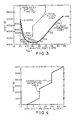
- Fig. 3 (solid line) illustrates direct operating cost versus flight time for the representative flight described above with the corresponding cost index values K illustrated along the curve.
- total flight cost is the sum of direct operating cost and arrival time error cost.
- T OPT generator 10 an arrival error cost function for the particular flight plan must be stored in the apparatus.
- the arrival error cost function is predefined and provided by the airline. The airline decides, based on crew overtime, losses due to. missed connections, potential losses resulting from customer dissatisfaction and airline policies regarding flight time pay, what it will cost for the aircraft to be late (or early) with respect to the scheduled arrival time.
- the arrival error costs are expectd to be different for each termination and therefore the arrival error cost functions will be generally different for each .arrival situation.
- the K OPT , T o p T generator 10, detailed in Figure 2, conveniently stores the AEC function in the following format:
- SIGMA(T, , S I , M I ) is a sloping step function of time which steps up for increasing positive T E , and also for decreasing negative T E .
- the set of time points ⁇ T I ⁇ are the AEC critical points.
- the SIGMA function is defined in terms of T i , S I , and M, by:
- an exemplary AEC function is illustrated comprised of a linear component of $600.00/hr. for T E ⁇ 0 and critical points at 0, 10, and 20 minutes. Two steps representing losses of $150.00 each, resulting from missed flight connections, are illustrated at 10 and 20 minutes. No cost penalty is assigned for early arrival.
- the AEC function of Figure 4 is represented in the SIGMA format by It will be appreciated that the AEC function is not necessarily comprised of linear segments. The segments between the steps may exhibit any appropriate functional curve. It will be appreciated, however, that in any event, the entire curve can be approximated by a series of piece-wise linear segments which may then be stored in the SIGMA format.
- the arrival error cost function of Figure 4 is added to the direct operating cost versus flight time function of Figure 3 to provide the total flight cost versus flight time function illustrated in dashed line.
- the arrival time error T E of Figure 4 is referenced to the scheduled arrival time T s of two hours and twenty minutes in deriving the total flight cost curve.
- the optimum flight time T OPT provided by the K OPT T o p T generator 10 of Figure 1 is determined from the minimum of the total flight cost curve of Figure 3. In the example illustrated, T OPT is approximately two hours and twenty-six minutes, or six minutes late.
- the optimum cost index resulting in the optimum flight time is in the range of 75 to 100 (approximately 85).
- On-time arrival would require a cost index of 900 and an additional cost of approximately $250.00.
- a cost index K of zero a connecting flight is missed and the total cost is approximately $200.00 more than the optimum. It will be appreciated that the optimum cost index is that which minimises J(K).
- Each point of the DOC curve of Figure 3 can be generated by performing a prediction pass for a trial cost index. This is generally an undesirably costly procedure with respect to FMS computer time and cannot be performed for a large number of trial cost index values without excessive response time. It is desirable to minimise the number of prediction passes in generating the true airspeed command V R in accordance with the invention.
- Top- r generator 10 of Figure 1 is predicated on the property that large variations in cost index near the optimum cost index value have a neglibible effect on total cost unless the minimum point of the total flight cost curve ( Figure 3) is proximate a critical point.
- the cost index can vary from about 30 to 130 with only a $10.00 variation in total cost. This variation in cost index corresponds to over four minutes variation in arrival time which is approximately 3% of the flight time. Therefore, the generation by the generator 10 of Figure 1 of the optimum cost index K o p- r does not have to be very precise and the optimum arrival time T o p T is only required to be precise if it is proximate a critical point.
- the preferred implementation of the generator 10 of Figure 1 for generating the optimum arrival time and cost index comprises utilising cost index values from a reference set thereof from which parabolic interpolation is utilised to estimate intermediate values.
- a preferred reference set, in units of 100 Ib/hr is:
- the scheduled arrival time is not necessarily the optimum arrival time.
- the generator 10 includes a block 40 for providing a time sequence of trial cost index values.
- the block 40 stores the reference set of cost index values discussed above (-100 through 1,000) and sequentially provides values -10, 25 and 150.
- the block 40 is also implemented to provide the next higher or next lower cost index value from the reference set in response to a signal on a line 41. Whether this new trial cost index value is a higher value or a lower value than the initially provided three values is controlled by a signal on a line 42.
- the operation of the block 40 is activated by the output of the OR gate 20 of Figure 1.
- Each trial cost index value from the block 20 is applied to a speed generator 43.
- the speed gen- rator 43 is identical to the speed generator 23 of Figure 1 and in a manner similar to the speed generator 23 receives the conventional simulated inputs, including simulated wind, and speed and acceleration limits from the block 25.
- the speed generator 43 provides a true airspeed signal corresponding to the input trial cost index value in the . manner described above with respect to the speed generator 23.
- the airspeed signal output of the speed generator 43 provides the airspeed input to a predictor 44.
- the predictor 44 is identical to the predictor 13 of Figure 1 as described above and receives the same conventional data inputs 14 that are applied to the predictor 13.
- the predictor 44 performs a prediction pass and provides a flight time to the destination T F (K) and the fuel burn to the destination F(K) corresponding to the trial cost index provided by the block 40.
- the present invention is applicable not only to flight time to the destination but to estimated time of arrival (ETA) at intermediate waypoints. When so utilised, the fuel burn and time outputs of the predictor 44 are with respect to such intermediate waypoints.
- ETA estimated time of arrival
- the F(K) and T F (K) outputs of the predictor 44 are applied to a direct operating cost function block 45.
- the block" 45 also receives the unit cost of fuel constant C F (cents/lb) as well as the K o input described above with respect to Figure 1.
- the direct operating cost function block 45 provides the direct operating cost (DOC) corresponding thereto in accordance with the DOC expression provided above.
- the flight time signal T F (K) from the predictor 44 and the direct operating cost signal (DOC) from the function block 45 are applied to a DOC vs. T F function generation block 46.
- the three flight time and DOC values corresponding to the initial three trial cost index values (-10, 25 and 150) are sequentially applied to the block 46 and stored therein.
- T F and DOC provide three equations from which A o , A 1 and A 2 may be derived.
- Ao coefficience
- a 1 and A 2 now known constants
- DOC is provided by the block 46 on a line 47 in response to a T F input on a line 48 utilising this parabolic polynomial.
- T F function in the block 46
- higher order polynomials may also be utilised to the same effect as well as other known means of curve fitting.
- Figure 3 illustrates the direct operating cost versus flight time curve for the representative flight discussed above.
- the K OPT , Top T generator 10 further includes an AEC function storage block 49 for storing the arrival time error cost function discussed above.
- the AEC function is stored in a piece-wise linear fashion pursuant to the SIGMA construction as explained hereinabove.
- the AEC function storage block 49 also receives a signal T s representative of the scheduled arrival time for the flight.
- a subtractor within the block 49 subtracts T s from trial flight time inputs T F to provide arrival time error T E .
- T E generates an AEC cost pursuant to the stored SIGMA function.
- the trial T F values are applied on a line 48 and the corresponding AEC cost values are applied to a line 50.
- the AEC function storage block 49 also provides the critical AEC time points on a line 51.
- the AEC function block 49 references the AEC critical points in terms of arrival time error T E to the scheduled arrival time T s by adding T E to T S to provide the AEC critical time points on the line 51.
- Figure 4 iflustrates a typical AEC function as described above.
- DOC on the line 47 and the value of AEC on the line 50 are applied to a summing function 52 to provide the sum thereof.
- the output of the summing function 52 is the total flight cost corresponding to the trial T F signal applied on the line 48.
- Figure 3 (dashed line) illustrates the total flight cost curve for the representative flight discussed above.
- the K OPT , T OPT generator 10 includes a search function block 53' which searches for the minimum point on the total flight cost curve to provide the optimum flight time T OPT .
- the search function 53 provides a sequence of trial T F values on the line 48 and the summing function 52 provides the total flight cost corresponding to the trial T F .
- the search function 53 begins at the earliest reasonable flight time TF that is prior to the scheduled arrival time and receives a total flight cost value that is stored therein. TF is increased by, for example, sixty seconds, or to the next occurring AEC critical point if this is prior to the sixty second increment, and a second value of total flight cost is received by the search function 53 and stored.
- the search function 53 sets the direction signal on the line 42 to be representative of increasing T F .
- the second value of total flight cost is compared to the first value thereof and if total flight cost is decreasing, the search is advanced by an additional sixty second increment or again to the next occurring critical point. The first value of total flight cost is then discarded. The search continues in this manner until total flight cost begins to increase. The previous trial T F value is then T OPT . Alternatively, upon reaching the trial T F value which results in the increased cost, the trial Tp may be decremented by, for example, ten seconds to provide T o p T .
- the trial Tp values are decremented in increments of sixty seconds, accounting for the AEC critical points as described above, until the minimum value is obtained to provide T o p T . If the direction of search is reversed, the direction signal on the line 42 is reversed to represent decreasing trial T F . It will be appreciated that all of the critical points within the search range are utilised in finding the minimum total flight cost value.
- the search function 53 issues a trial Tp value that corresponds to an end point of the DOC vs. TFfunction stored in the block 46 without attaining the minimum value, a signal representative of minimum-not is applied to the line 41.
- the end point of the DOC vs. T F function corresponds to the end point of the range of trial cost index values provided by the block 40. If the minimum total flight cost point is not attained, as indicated by the signal on the line 41, the block 40 provides the next occurring cost index value in the reference set and the apparatus adds a point corresponding thereto to the DOC vs. T F function stored in the block 46 in the manner described above.
- the search function 53 searches for the minimum total flight cost value on the extended total flight cost curve.
- the trial K block 40 selects the next occurring trial cost index value in the direction indicated by the direction signal on the line 42. If the direction signal on the line 42 is representative of increasing T F , the next smaller cost index value is utilised. If the direction signal on the line 42 is representative of decreasing T F , the next larger cost index value is issued by the block 40.
- the. corresponding trial T F is issued on a line 54 as the signal T o p T .
- the K oPT , T o p T generator 10 further includes a K vs T F function generation block 55.
- the block 55 receives as inputs the trial cost index values provided from the block 40 and the corresponding flight time signal T F (K) from the predictor 44.
- the function generating block 55 generates a parabolic approximation of the K vs T F curve in the same manner as described above with respect to the block 46.
- the minimum-not signal on the line 41 is applied to the function blocks 46 and 55 to control extending the curves stored therein when the search function 53 determines that a minimum has not been attained as described above.
- the T o p T signal on the line 54 is applied to the function block 55 which provides the corresponding cost index value on a line 56 as K OPT .
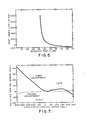
- Figure 5 illustrates the flight time versus cost index function corresponding to the representative flight described above.
- the apparatus and method described above represents a practical compromise between accuracy and processing load, predicated on the property that the total flight cost curve is relatively insensitive to change in cost index, and that sensitivity to arrival time is significant only in the vicinity of the AEC critical points, such as the - scheduled arrival time or connecting flight times. Since these critical points are predefined and utilised in the search procedure, the accuracy of an optimum point at a critical time is ensured. The procedure will normally require only three prediction passes.
- T OPT generator 10 which generates the complete curves to any desired resolution.
- a block 60 provides a sequence of cost index values with arbitrary resolution over the full range thereof.
- the generator 10 is activated by the output of the OR gate 20 of Figure 1 as discussed above with respect to Figure 2.
- Each value of K is processed by the speed generator 43, the predictor 44 and the DOC block 45 in the manner discussed above with respect to Figure 2.
- the values of DOC and T F (K) are applied to a DOC vs. T F function block 61 where the full range of curve values are stored therein in, for example, tabular form.
- the AEC function is stored in the block 49 in the manner described above with respect to Figure 2 and combined with DOC by the summing function 52.
- a search function 62 provides the trial T F values to the blocks 61 and 49 to search for the minimum of the total flight cost curve in the manner described above with respect to Figure 2. Since the entire range of values is initially generated and stored in the block 61, the search function 62 determines the minimum T o p T without utilising the minimum-not signal on the line 41 and the direction signal on the line 42 as described above with respect to Figure 2.
- the generator 10 of Figure 6 also includes a K vs T F function generator 63 that stores the full range of cost index values from the block 60 and the corresponding T F (K) values from the predictor 44 in, for example, tabular form.
- the T OPT signal on the line 54 is then translated by table lookup into the corresponding K o p T value on the line 56.
- timing circuitry and control signals are applied to the various blocks to control the sequence of events described above.
- the DOC vs. T F functions in the blocks 46 ( Figure 2) and 61 ( Figure 6) are first generated and then the search functions 53 ( Figure 2) and 62 ( Figure 6) perform the search in timed fashion thereafter.
- the various component blocks of Figures 1, 2 and 6 are preferably functional program segments of a stored program digital computer embodiment of the invention. In such a stored program version of the invention, it will be appreciated that the multiple uses of the predictor and the speed generator would be implemented in the software embodiment by calling the speed generator routine and the predictor routine when required, with appropriate inputs applied thereto. Alternatively, each of the blocks may be implemented, in a conventional manner, by discrete analogue or digital logic circuits.
- T o p T generator 10 After the Kpp T , T o p T generator 10 provides the otpimal arrival time Tpp T and the approximately optimal cost index K o p T , the apparatus of Figure 1 then fine-tunes the speed to obtain the high arrival time accuracy provided by the signal V R as described above.
- FIG. 7 a diagram demonstrating convergence of the speed adjustment performed in the manner described above is illustrated.
- the previously described representative flight was executed with no wind and a cost index of zero, which results in a flight time of 2:19:58.
- Fourteen situations of time constraints were performed, corresponding to required arrival time that deviates from the resulting flight time by ⁇ 15 seconds, ⁇ 30 seconds, ⁇ 1 minute, ⁇ 2 minutes, ⁇ 3 minutes, ⁇ 4 minutes and ⁇ 5 minutes.
- Figure 7 illustrates the result of the speed adjustment of the apparatus of Figure 1 after one and two adjustments. For example, if the non-adjusted speed results in a three- minute late arrival, then the first adjustment reduces the arrival error to 3.6 seconds and the second adjustment to -0.5 seconds.
- the early arrival situations tend to over adjust on the first adjustment.
- the result of the first adjustment was a 43-second late arrival.
- the second adjustment results in a 4.3- second early arrival.
- Figure 7 illustrates the rapidity with which the speed adjustment procedure converges. With just one or two prediction passes, the speed adjustment apparatus and procedure of the present invention provides very high arrival time accuracy.
- the present invention provides a practical method for generating the true airspeed command in an FMS that results in minimum total flight cost.
- the method is comprised of two parts:
Landscapes
- Engineering & Computer Science (AREA)
- Aviation & Aerospace Engineering (AREA)
- Radar, Positioning & Navigation (AREA)
- Remote Sensing (AREA)
- Physics & Mathematics (AREA)
- General Physics & Mathematics (AREA)
- Automation & Control Theory (AREA)
- Traffic Control Systems (AREA)
- Control Of Position, Course, Altitude, Or Attitude Of Moving Bodies (AREA)
Applications Claiming Priority (2)
| Application Number | Priority Date | Filing Date | Title |
|---|---|---|---|
| US875115 | 1986-06-17 | ||
| US06/875,115 US4760530A (en) | 1986-06-17 | 1986-06-17 | Flight management system providing minimum total cost |
Publications (3)
| Publication Number | Publication Date |
|---|---|
| EP0250140A2 true EP0250140A2 (de) | 1987-12-23 |
| EP0250140A3 EP0250140A3 (en) | 1989-05-24 |
| EP0250140B1 EP0250140B1 (de) | 1992-09-30 |
Family
ID=25365226
Family Applications (1)
| Application Number | Title | Priority Date | Filing Date |
|---|---|---|---|
| EP87305051A Expired EP0250140B1 (de) | 1986-06-17 | 1987-06-08 | Flugverwaltungssystem |
Country Status (4)
| Country | Link |
|---|---|
| US (1) | US4760530A (de) |
| EP (1) | EP0250140B1 (de) |
| JP (1) | JPS62299498A (de) |
| DE (1) | DE3781941T2 (de) |
Cited By (9)
| Publication number | Priority date | Publication date | Assignee | Title |
|---|---|---|---|---|
| EP0637787A1 (de) * | 1993-08-03 | 1995-02-08 | Honeywell Inc. | Vorrichtung und Methode zum Betreiben eines Flugoptimierungsrechners um Daten für zeitbeschränkte Navigation zu erhalten |
| WO1997048028A1 (fr) * | 1996-06-14 | 1997-12-18 | Sextant Avionique | Systeme de gestion de vol d'aerodynes |
| FR2916842A1 (fr) * | 2007-06-01 | 2008-12-05 | Thales Sa | Procede d'optimisation d'un plan de vol |
| FR2938939A1 (fr) * | 2008-11-25 | 2010-05-28 | Thales Sa | Procede d'aide a la gestion du vol d'un aeronef en vue de tenir une contrainte de temps |
| FR2939917A1 (fr) * | 2008-12-12 | 2010-06-18 | Thales Sa | Procede et dispositif pour l'optimisation du vol d'un aeronef |
| FR2953302A1 (fr) * | 2009-11-27 | 2011-06-03 | Thales Sa | Procede de planification, de calcul de trajectoire, de predictions et de guidage pour le respect d'une contrainte de temps de passage d'un aeronef |
| EP2685292A3 (de) * | 2012-07-12 | 2014-06-18 | General Electric Company | Systeme und Verfahren für Flugmanagement |
| EP3193268A1 (de) * | 2016-01-13 | 2017-07-19 | The Boeing Company | Systeme und verfahren zur bereitstellung von flugzeugleistungsberechnungen |
| US10144505B2 (en) * | 2015-05-18 | 2018-12-04 | The Boeing Company | Aircraft flight control using a required time of arrival index |
Families Citing this family (29)
| Publication number | Priority date | Publication date | Assignee | Title |
|---|---|---|---|---|
| US5406488A (en) * | 1987-05-06 | 1995-04-11 | The Secretary Of State For Defence In Her Britannic Majesty's Government Of The United Kingdom Of Great Britain And Northern Ireland | Correction of errors in autopilots |
| US5051910A (en) * | 1989-10-16 | 1991-09-24 | Honeywell Inc. | Wind forecast error compensation for 4-D guidance in a aircraft flight management system |
| US5121325A (en) * | 1990-04-04 | 1992-06-09 | Smiths Industries Aerospace & Defense Systems, Inc. | Required time of arrival (RTA) control system |
| FR2761176B1 (fr) * | 1997-03-18 | 1999-05-14 | Aerospatiale | Procede et dispositif pour determiner un trajet de vol optimal d'un aeronef |
| US6085147A (en) * | 1997-09-26 | 2000-07-04 | University Corporation For Atmospheric Research | System for determination of optimal travel path in a multidimensional space |
| US7664601B2 (en) * | 1999-11-10 | 2010-02-16 | Honeywell International Inc. | Weather incident prediction |
| DE60016448T2 (de) * | 1999-11-10 | 2005-12-08 | Honeywell International Inc. | Wetterstörungsvorhersage |
| US7346530B2 (en) * | 2001-01-31 | 2008-03-18 | Dell Products L.P. | Flexible ordering of inventory from material sources according to material requirements for manufacturing operations |
| US6507782B1 (en) * | 2001-05-14 | 2003-01-14 | Honeywell International Inc. | Aircraft control system for reaching a waypoint at a required time of arrival |
| US7099341B2 (en) * | 2002-05-03 | 2006-08-29 | International Business Machines Corporation | Traffic routing management system using the open shortest path first algorithm |
| US7647163B2 (en) * | 2005-08-04 | 2010-01-12 | The Boeing Company | Automated fueling information tracking and fuel hedging |
| US7606641B2 (en) * | 2005-08-04 | 2009-10-20 | The Boeing Company | Fuel consumption data tracking/collection and aircraft/route optimization |
| FR2894705B1 (fr) * | 2005-12-13 | 2010-11-19 | Thales Sa | Systeme de gestion de vol d'un aeronef |
| US20080004926A1 (en) * | 2006-06-30 | 2008-01-03 | Microsoft Corporation | Methods and architectures for context-sensitive reminders and service facilitation |
| US20080086290A1 (en) * | 2006-10-04 | 2008-04-10 | Wilson Ian A | Method for modeling task and workload |
| US8560376B2 (en) * | 2007-05-31 | 2013-10-15 | Airbus Operations S.A.S. | Method, system, and computer program product for a maintenance optimization model |
| US7606658B2 (en) * | 2007-09-12 | 2009-10-20 | Honeywell International Inc. | Financial decision aid for 4-D navigation |
| US9257047B2 (en) * | 2007-12-12 | 2016-02-09 | The Boeing Company | Computation of new aircraft trajectory using time factor |
| US20090265049A1 (en) * | 2008-04-22 | 2009-10-22 | Honeywell International, Inc. | Aircraft system emissions and noise estimation mechanism |
| US9134137B2 (en) | 2010-12-17 | 2015-09-15 | Microsoft Technology Licensing, Llc | Mobile search based on predicted location |
| US8280626B2 (en) * | 2011-02-15 | 2012-10-02 | General Electric Company | Method for selecting meteorological data for updating an aircraft trajectory |
| US20120209646A1 (en) * | 2011-02-16 | 2012-08-16 | Francesco Montrone | Method and computer program product for optimization of maintenance plans |
| US9163952B2 (en) | 2011-04-15 | 2015-10-20 | Microsoft Technology Licensing, Llc | Suggestive mapping |
| US20130226373A1 (en) * | 2012-02-27 | 2013-08-29 | Ge Aviation Systems Llc | Methods for in-flight adjusting of a flight plan |
| US9601021B2 (en) * | 2015-07-07 | 2017-03-21 | The Boeing Company | Retrospective analysis of vehicle operations |
| US9690426B1 (en) * | 2015-07-27 | 2017-06-27 | Rockwell Collins, Inc. | Heuristic touch interface system and method |
| US10832581B2 (en) * | 2017-03-31 | 2020-11-10 | General Electric Company | Flight management via model-based iterative optimization |
| US11320842B2 (en) * | 2018-10-01 | 2022-05-03 | Rockwell Collins, Inc. | Systems and methods for optimized cruise vertical path |
| US12522372B2 (en) * | 2023-09-13 | 2026-01-13 | The Boeing Company | Systems and methods for increasing fuel efficiency for an aircraft |
Family Cites Families (5)
| Publication number | Priority date | Publication date | Assignee | Title |
|---|---|---|---|---|
| CH584940A5 (de) * | 1974-08-07 | 1977-02-15 | Soechtig Gerhard | |
| US4159088A (en) * | 1977-01-03 | 1979-06-26 | The Boeing Company | System for reducing aircraft fuel consumption |
| US4312041A (en) * | 1978-02-22 | 1982-01-19 | Lear Siegler, Inc. | Flight performance data computer system |
| US4325123A (en) * | 1978-07-28 | 1982-04-13 | The Boeing Company | Economy performance data avionic system |
| US4642775A (en) * | 1984-05-25 | 1987-02-10 | Sundstrand Data Control, Inc. | Airborne flight planning and information system |
-
1986
- 1986-06-17 US US06/875,115 patent/US4760530A/en not_active Expired - Lifetime
-
1987
- 1987-05-30 JP JP62137624A patent/JPS62299498A/ja active Pending
- 1987-06-08 EP EP87305051A patent/EP0250140B1/de not_active Expired
- 1987-06-08 DE DE8787305051T patent/DE3781941T2/de not_active Expired - Fee Related
Non-Patent Citations (1)
| Title |
|---|
| PROCEEDINGS OF THE 1985 AMERICAN CONTROL CONFERENCE, Boston, 19th-21nd June 1985, pages 675-681, Boston, US; S. LIDEN: "Practical considerations in optimal flight management computations" * |
Cited By (15)
| Publication number | Priority date | Publication date | Assignee | Title |
|---|---|---|---|---|
| EP0637787A1 (de) * | 1993-08-03 | 1995-02-08 | Honeywell Inc. | Vorrichtung und Methode zum Betreiben eines Flugoptimierungsrechners um Daten für zeitbeschränkte Navigation zu erhalten |
| WO1997048028A1 (fr) * | 1996-06-14 | 1997-12-18 | Sextant Avionique | Systeme de gestion de vol d'aerodynes |
| FR2749933A1 (fr) * | 1996-06-14 | 1997-12-19 | Sextant Avionique | Procede pour la gestion de la vitesse air en vue du respect des contraintes de temps d'un aerodyne dans un environnement meteorologique evolutif |
| US8565938B2 (en) | 2007-06-01 | 2013-10-22 | Thales | Method of optimizing a flight plan |
| FR2916842A1 (fr) * | 2007-06-01 | 2008-12-05 | Thales Sa | Procede d'optimisation d'un plan de vol |
| FR2938939A1 (fr) * | 2008-11-25 | 2010-05-28 | Thales Sa | Procede d'aide a la gestion du vol d'un aeronef en vue de tenir une contrainte de temps |
| US8473120B2 (en) | 2008-11-25 | 2013-06-25 | Thales | Method for assisting in the management of the flight of an aircraft in order to keep to a time constraint |
| FR2939917A1 (fr) * | 2008-12-12 | 2010-06-18 | Thales Sa | Procede et dispositif pour l'optimisation du vol d'un aeronef |
| US8255148B2 (en) | 2008-12-12 | 2012-08-28 | Thales | Method and device for optimizing the flight of an aircraft |
| FR2953302A1 (fr) * | 2009-11-27 | 2011-06-03 | Thales Sa | Procede de planification, de calcul de trajectoire, de predictions et de guidage pour le respect d'une contrainte de temps de passage d'un aeronef |
| US8744768B2 (en) | 2009-11-27 | 2014-06-03 | Thales | Method of planning, trajectory computation, predictions and guidance for compliance with an aircraft flypast time constraint |
| EP2685292A3 (de) * | 2012-07-12 | 2014-06-18 | General Electric Company | Systeme und Verfahren für Flugmanagement |
| US10144505B2 (en) * | 2015-05-18 | 2018-12-04 | The Boeing Company | Aircraft flight control using a required time of arrival index |
| EP3193268A1 (de) * | 2016-01-13 | 2017-07-19 | The Boeing Company | Systeme und verfahren zur bereitstellung von flugzeugleistungsberechnungen |
| US10071818B2 (en) | 2016-01-13 | 2018-09-11 | The Boeing Company | Systems and methods for providing airplane performance calculations |
Also Published As
| Publication number | Publication date |
|---|---|
| EP0250140B1 (de) | 1992-09-30 |
| US4760530A (en) | 1988-07-26 |
| EP0250140A3 (en) | 1989-05-24 |
| JPS62299498A (ja) | 1987-12-26 |
| DE3781941D1 (de) | 1992-11-05 |
| DE3781941T2 (de) | 1993-04-01 |
Similar Documents
| Publication | Publication Date | Title |
|---|---|---|
| EP0250140B1 (de) | Flugverwaltungssystem | |
| US5051910A (en) | Wind forecast error compensation for 4-D guidance in a aircraft flight management system | |
| CN108693889B (zh) | 经由基于模型的迭代优化而实现的飞行管理 | |
| US5574647A (en) | Apparatus and method for computing wind-sensitive optimum altitude steps in a flight management system | |
| US5070458A (en) | Method of analyzing and predicting both airplane and engine performance characteristics | |
| EP0637787B1 (de) | Vorrichtung und Methode zum Betreiben eines Flugoptimierungsrechners um Daten für zeitbeschränkte Navigation zu erhalten | |
| US10935984B2 (en) | Method and system for determining a climb profile | |
| EP2631732B1 (de) | Verfahren zum Fliegen eines Flugzeugs entlang eines Flugpfads | |
| US5457634A (en) | Time-responsive flight optimization system | |
| CA2781949C (en) | Meteorological modeling along an aircraft trajectory | |
| US20130226373A1 (en) | Methods for in-flight adjusting of a flight plan | |
| CN102645931A (zh) | 用于选择气象数据以用于更新飞行器轨迹的方法 | |
| US20100152927A1 (en) | Method and device for optimizing the flight of an aircraft | |
| CN105701552B (zh) | 一种飞行航路垂直剖面的确定方法 | |
| CA3006525C (en) | Flight management system having performance table datalink capability | |
| US6061612A (en) | Aircraft flight management system | |
| CN114283624B (zh) | 一种基于空地航迹信息共享的飞机位置预测方法 | |
| Porretta et al. | Performance evaluation of a novel 4D trajectory prediction model for civil aircraft | |
| US11142337B2 (en) | Method and system for determining a descent profile | |
| US20190061971A1 (en) | Flight Management System Having Customized Performance Database | |
| EP3974937B1 (de) | Verfahren und system zur bestimmung eines sinkprofils | |
| JPS5881897A (ja) | 航空機用速度制御装置 | |
| US20040070521A1 (en) | System and method for reducing the speed of an aircraft | |
| CN118605351B (zh) | 一种可控制的fpga航空发动机ecu软件系统 | |
| EP0482250B1 (de) | Luftgeschwindigkeitsregelsystem für Flugzeugvortriebsregler |
Legal Events
| Date | Code | Title | Description |
|---|---|---|---|
| PUAI | Public reference made under article 153(3) epc to a published international application that has entered the european phase |
Free format text: ORIGINAL CODE: 0009012 |
|
| AK | Designated contracting states |
Kind code of ref document: A2 Designated state(s): DE FR GB IT |
|
| PUAL | Search report despatched |
Free format text: ORIGINAL CODE: 0009013 |
|
| AK | Designated contracting states |
Kind code of ref document: A3 Designated state(s): DE FR GB IT |
|
| 17P | Request for examination filed |
Effective date: 19890516 |
|
| 17Q | First examination report despatched |
Effective date: 19910314 |
|
| ITTA | It: last paid annual fee | ||
| GRAA | (expected) grant |
Free format text: ORIGINAL CODE: 0009210 |
|
| AK | Designated contracting states |
Kind code of ref document: B1 Designated state(s): DE FR GB IT |
|
| ITF | It: translation for a ep patent filed | ||
| REF | Corresponds to: |
Ref document number: 3781941 Country of ref document: DE Date of ref document: 19921105 |
|
| ET | Fr: translation filed | ||
| PLBE | No opposition filed within time limit |
Free format text: ORIGINAL CODE: 0009261 |
|
| STAA | Information on the status of an ep patent application or granted ep patent |
Free format text: STATUS: NO OPPOSITION FILED WITHIN TIME LIMIT |
|
| 26N | No opposition filed | ||
| REG | Reference to a national code |
Ref country code: GB Ref legal event code: IF02 |
|
| PGFP | Annual fee paid to national office [announced via postgrant information from national office to epo] |
Ref country code: GB Payment date: 20030501 Year of fee payment: 17 |
|
| PGFP | Annual fee paid to national office [announced via postgrant information from national office to epo] |
Ref country code: FR Payment date: 20030602 Year of fee payment: 17 |
|
| PGFP | Annual fee paid to national office [announced via postgrant information from national office to epo] |
Ref country code: DE Payment date: 20030630 Year of fee payment: 17 |
|
| PG25 | Lapsed in a contracting state [announced via postgrant information from national office to epo] |
Ref country code: GB Free format text: LAPSE BECAUSE OF NON-PAYMENT OF DUE FEES Effective date: 20040608 |
|
| PG25 | Lapsed in a contracting state [announced via postgrant information from national office to epo] |
Ref country code: DE Free format text: LAPSE BECAUSE OF NON-PAYMENT OF DUE FEES Effective date: 20050101 |
|
| GBPC | Gb: european patent ceased through non-payment of renewal fee |
Effective date: 20040608 |
|
| PG25 | Lapsed in a contracting state [announced via postgrant information from national office to epo] |
Ref country code: FR Free format text: LAPSE BECAUSE OF NON-PAYMENT OF DUE FEES Effective date: 20050228 |
|
| REG | Reference to a national code |
Ref country code: FR Ref legal event code: ST |
|
| PG25 | Lapsed in a contracting state [announced via postgrant information from national office to epo] |
Ref country code: IT Free format text: LAPSE BECAUSE OF NON-PAYMENT OF DUE FEES;WARNING: LAPSES OF ITALIAN PATENTS WITH EFFECTIVE DATE BEFORE 2007 MAY HAVE OCCURRED AT ANY TIME BEFORE 2007. THE CORRECT EFFECTIVE DATE MAY BE DIFFERENT FROM THE ONE RECORDED. Effective date: 20050608 |
|
| P01 | Opt-out of the competence of the unified patent court (upc) registered |
Effective date: 20230525 |