EP0250072A2 - Spannzangenverbindung - Google Patents
Spannzangenverbindung Download PDFInfo
- Publication number
- EP0250072A2 EP0250072A2 EP87303623A EP87303623A EP0250072A2 EP 0250072 A2 EP0250072 A2 EP 0250072A2 EP 87303623 A EP87303623 A EP 87303623A EP 87303623 A EP87303623 A EP 87303623A EP 0250072 A2 EP0250072 A2 EP 0250072A2
- Authority
- EP
- European Patent Office
- Prior art keywords
- tubular member
- fingers
- collet
- ring
- tubular
- Prior art date
- Legal status (The legal status is an assumption and is not a legal conclusion. Google has not performed a legal analysis and makes no representation as to the accuracy of the status listed.)
- Granted
Links
Images
Classifications
-
- E—FIXED CONSTRUCTIONS
- E21—EARTH OR ROCK DRILLING; MINING
- E21B—EARTH OR ROCK DRILLING; OBTAINING OIL, GAS, WATER, SOLUBLE OR MELTABLE MATERIALS OR A SLURRY OF MINERALS FROM WELLS
- E21B17/00—Drilling rods or pipes; Flexible drill strings; Kellies; Drill collars; Sucker rods; Cables; Casings; Tubings
- E21B17/02—Couplings; joints
- E21B17/04—Couplings; joints between rod or the like and bit or between rod and rod or the like
- E21B17/046—Couplings; joints between rod or the like and bit or between rod and rod or the like with ribs, pins, or jaws, and complementary grooves or the like, e.g. bayonet catches
-
- F—MECHANICAL ENGINEERING; LIGHTING; HEATING; WEAPONS; BLASTING
- F16—ENGINEERING ELEMENTS AND UNITS; GENERAL MEASURES FOR PRODUCING AND MAINTAINING EFFECTIVE FUNCTIONING OF MACHINES OR INSTALLATIONS; THERMAL INSULATION IN GENERAL
- F16L—PIPES; JOINTS OR FITTINGS FOR PIPES; SUPPORTS FOR PIPES, CABLES OR PROTECTIVE TUBING; MEANS FOR THERMAL INSULATION IN GENERAL
- F16L37/00—Couplings of the quick-acting type
- F16L37/002—Couplings of the quick-acting type which can be controlled at a distance
-
- Y—GENERAL TAGGING OF NEW TECHNOLOGICAL DEVELOPMENTS; GENERAL TAGGING OF CROSS-SECTIONAL TECHNOLOGIES SPANNING OVER SEVERAL SECTIONS OF THE IPC; TECHNICAL SUBJECTS COVERED BY FORMER USPC CROSS-REFERENCE ART COLLECTIONS [XRACs] AND DIGESTS
- Y10—TECHNICAL SUBJECTS COVERED BY FORMER USPC
- Y10S—TECHNICAL SUBJECTS COVERED BY FORMER USPC CROSS-REFERENCE ART COLLECTIONS [XRACs] AND DIGESTS
- Y10S285/00—Pipe joints or couplings
- Y10S285/92—Remotely controlled
Definitions
- Collet connectors are commonly used to provide a remotely actuated connection between tubular members such as pipelines or other tubular members.
- tubular members such as pipelines or other tubular members.
- collet connectors the ends of the tubular members have a different configuration.
- the A. G. Ahlstone Patent No. 3,321,217 dated May 23, 1967 discloses another type of joint construction which is controlled by remote actuation to move latching segments into multiple grooves in the exterior of one member and the segments are secured to the other tubular member.
- the present invention relates to an improved remotely actuated connector which is suitable for connecting between similar or different types of end preparations on the tubular members being connected.
- the improved connector is a collet connector having collet fingers actuated by a ring which is moved by an actuator.
- the collet fingers include adapters which are readily secured to the fingers and which can convert the ends of the collet fingers to engage more than one type of end preparation.
- An object of the present invention is to provide an improved type of collet connector which may be used with more than one type of end preparation on the tubular members to be connected.
- a further object is to provide an improved type of collet connector which may remotely connect tubular members with different end preparations and which accommodates different configurations of sealing surfaces.
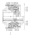
- FIGURE 1 Remotely actuated collet connector 10 of the prior art is shown in FIGURE 1 with FIGURE 1A illustrating the connector 10 in its locking position joining first tubular member 12 to second tubular member 14 and with FIGURE 1B illustrating connector 10 mounted on first tubular member 12 but with second tubular member 14 removed.
- Connector 10 includes housing 16 secured to flange 18 of first tubular member 12 and extending axially in surrounding relationship over the position into which second tubular member 14 is positioned for the connection.
- Upper and lower annular operating cylinders 28 and 32 are bounded by annular lip 20 of housing 16 which extends inwardly from housing 16 and includes seals 22, such as O rings, positioned in grooves on the inner surface 24 of lip 20.
- Passage 26 extends through flange 18 and through housing 16 and opens into upper cylinder 28 above lip 20.
- Passage 30 extends through flange 18 and through housing 16 and opens into lower cylinder 32 on the opposite side of lip 20 from cylinder 28.
- Actuator ring 34 is positioned within housing 16 and includes flange 36 extending outwardly with seals 38 in its outer surface 40 to seal against the upper inner surface 42 of housing 16.
- Latching fingers or segments 44 are positioned within actuator ring 34 and are closely spaced together as best seen in FIGURE 1B.
- Latching fingers 44 include shoulders 46 and 48 on projections 50 and 52 and are adapted to engage and secure tapered shoulders 54 and 56 on first and second tubular members 12 and 14. Shoulders 54 and 56 are similar end preparations for which the collet connections of the prior art were adapted to connect.
- Metal seal ring 58 is positioned between the inner ends of first and second tubular members 12 and 14 and seals against the inner tapered surfaces 60 and 62 of members 12 and 14, respectively.
- Seal ring 58 includes outer diameter enlargement 61 which is used to secure seal ring 58 to first tubular member 12 by suitable means such as bolting (not shown).
- Cylinder head ring 64 is secured to the exterior surface of actuator ring 34 at its lower outer end; is suitably attached thereto by retainer 65 and split ring 67; and is sealed to the lower interior surface 66 of housing 16 and to actuator ring 34 as shown.
- Retainer ring 65 is secured by bolting (not shown) to cylinder head ring 64.
- FIGURE 1A the two tubular members 12 and 14 are connected to one another in sealed locking engagement by the actuation of ring 34 in the downward direction to move fingers 44 into tight clamping engagement with shoulders 54 and 56 and to sealingly engage metal seal ring 58 between surfaces 60 and 62 of members 12 and 14.
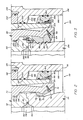
- Improved collet connector 110 is illustrated in one of its forms in FIGURE 2.
- Connector 110 is similar to connector 10 and similar components are given the same number with the prefix 1, e.g., first tubular member 112.
- Connector 110 includes housing 116 secured to flange (not shown) of first tubular member 112 and extending axially in surrounding relationship over the position into which second tubular member 114 is positioned for the connection.
- Upper and lower annular operating cylinders 128 and 132 are bounded by annular lip 120 of housing 116 which extends inwardly from housing 116 and includes seals 122, such as O rings, positioned in grooves on the inner surface 124 of lip 120.
- Passage 126 extends through the flange (not shown) on member 112 and through housing 116 and opens into upper cylinder 128 above lip 120.
- Another passage (not shown) extends through the flange on member 112 and through housing 116 and opens into lower cylinder 132 on the opposite side of lip 120 from cylinder 128.
- Actuator ring 134 is positioned within housing 116 and includes a flange (not shown) extending outwardly and sealing against the inner surface 142 of housing 116.
- Latching fingers 70 each include adapters 72 which are secured to the inner surface of fingers 70. Cap screws 74 and projections 76 are utilized to secure adapters 72 to fingers 70. Latching fingers 70 include shoulder 146 on projection 150 which engages tapered shoulder 154 on first tubular member 112 and shoulder 78 on adapter 72 which engages tapered shoulder 156 on second tubular member 114.
- Metal seal ring 158 is positioned between the inner ends of first and second tubular members 112 and 114 and seals against the inner tapered surfaces 160 and 162 of members 112 and 114, respectively.
- Seal ring 158 includes outer diameter enlargement 161 which is used to secure seal ring 158 to first tubular means 112 by suitable means such as bolting (not shown).
- Cylinder head ring 164 is secured to the exterior surface of actuator ring 134 at its lower outer end and is suitably attached thereto by retainer 165 and split ring 167 and is sealed to the lower interior surface 166 of housing 116 and to actuator ring 134 as shown.
- Retainer 165 is secured to cylinder head ring 164 by bolts 169.
- Improved collet connector 210 is illustrated in one of its forms in FIGURE 3.
- Connector 210 is similar to connector 10 and similar components are given the same number with the prefix 2, e.g., the first tubular member 212.
- Connector 210 includes housing 216 secured to flange (not shown) of first tubular member 212 and extending axially in surrounding relationship over the position into which second tubular member 214 is positioned for the connection.
- Upper and lower annular operating cylinders 228 and 232 are bounded by annular lip 220 of housing 216 which extends inwardly from housing 216 and includes seals 222, such as O rings, positioned in grooves on the inner surface 224 of lip 220.
- Passage 226 extends through the flange (not shown) on member 212 and through housing 216 and opens into upper cylinder 228 above lip 220.
- Another passage (not shown) extends through the flange on member 212 and through housing 216 and opens into lower cylinder 232 on the opposite side of lip 220 from cylinder 228.
- Actuator ring 234 is positioned within housing 216 and includes a flange (not shown) extending outwardly and sealing against the inner surface 242 of housing 216.
- Latching fingers 80 each include adapters 82 which are secured to the inner surface of fingers 80. Cap screws 84 and projections 86 are utilized to secure adapters 82 to fingers 80. Latching fingers 80 include shoulder 246 on projection 250 which engages tapered shoulder 254 on first tubular member 212 and projections 88 on adapter 82 which engage within grooves 90 on the exterior of second tubular member 214. Additionally alignment ring 92 is secured to the lower end of first tubular member 212 by cap screws 94 to assist in guiding tubular member 212 and latching fingers 80 onto tubular member 214.
- Metal seal ring 258 is positioned between the inner ends of first and second tubular members 212 and 214 and seals against the inner tapered surfaces 260 and 98 of members 212 and 214, respectively.
- Seal ring 258 includes outer diameter enlargement 261 which is used to secure seal ring 258 to first tubular member 212 by suitable means such as bolting (not shown).
- Cylinder head ring 264 is secured to the exterior surface of actuator ring 234 at its lower outer end and is suitably attached thereto by retainer 265 and split ring 267 and is sealed to the lower interior surface 266 of housing 216 and to actuator ring 234 as shown.
- Retainer 265 is secured to cylinder head ring 264 by bolts 269.
- the delivery of fluid under pressure through passage 26 to chamber 28 causes actuator ring 34 to move upwardly toward flange 18; and through passage 30 to chamber 32 causes actuator ring 34 to move downwardly away from flange 18.
Landscapes
- Engineering & Computer Science (AREA)
- General Engineering & Computer Science (AREA)
- Mechanical Engineering (AREA)
- Life Sciences & Earth Sciences (AREA)
- Geology (AREA)
- Mining & Mineral Resources (AREA)
- Physics & Mathematics (AREA)
- Environmental & Geological Engineering (AREA)
- Fluid Mechanics (AREA)
- General Life Sciences & Earth Sciences (AREA)
- Geochemistry & Mineralogy (AREA)
- Quick-Acting Or Multi-Walled Pipe Joints (AREA)
- Mutual Connection Of Rods And Tubes (AREA)
- Infusion, Injection, And Reservoir Apparatuses (AREA)
- Telephone Function (AREA)
- Pharmaceuticals Containing Other Organic And Inorganic Compounds (AREA)
- Portable Nailing Machines And Staplers (AREA)
- Non-Silver Salt Photosensitive Materials And Non-Silver Salt Photography (AREA)
- Cable Accessories (AREA)
- Non-Disconnectible Joints And Screw-Threaded Joints (AREA)
- Earth Drilling (AREA)
- External Artificial Organs (AREA)
- Measuring Pulse, Heart Rate, Blood Pressure Or Blood Flow (AREA)
- Adornments (AREA)
- Cyclones (AREA)
Priority Applications (1)
| Application Number | Priority Date | Filing Date | Title |
|---|---|---|---|
| AT87303623T ATE62733T1 (de) | 1986-06-19 | 1987-04-24 | Spannzangenverbindung. |
Applications Claiming Priority (2)
| Application Number | Priority Date | Filing Date | Title |
|---|---|---|---|
| US06/876,086 US4693497A (en) | 1986-06-19 | 1986-06-19 | Collet connector |
| US876086 | 1986-06-19 |
Publications (3)
| Publication Number | Publication Date |
|---|---|
| EP0250072A2 true EP0250072A2 (de) | 1987-12-23 |
| EP0250072A3 EP0250072A3 (en) | 1988-07-06 |
| EP0250072B1 EP0250072B1 (de) | 1991-04-17 |
Family
ID=25366975
Family Applications (1)
| Application Number | Title | Priority Date | Filing Date |
|---|---|---|---|
| EP87303623A Expired - Lifetime EP0250072B1 (de) | 1986-06-19 | 1987-04-24 | Spannzangenverbindung |
Country Status (10)
| Country | Link |
|---|---|
| US (1) | US4693497A (de) |
| EP (1) | EP0250072B1 (de) |
| JP (1) | JPS631893A (de) |
| AT (1) | ATE62733T1 (de) |
| BR (1) | BR8703065A (de) |
| CA (1) | CA1303093C (de) |
| DE (1) | DE3769375D1 (de) |
| MX (1) | MX167126B (de) |
| NO (1) | NO173711C (de) |
| SG (1) | SG66091G (de) |
Cited By (24)
| Publication number | Priority date | Publication date | Assignee | Title |
|---|---|---|---|---|
| US5050843A (en) * | 1990-08-15 | 1991-09-24 | Manifold Systems, Inc. | Plug valve with metal-to-metal sealing |
| GB2322176A (en) * | 1997-02-15 | 1998-08-19 | Vetco Gray Inc Abb | Wellhead connector with interchangeable locking members |
| US20180245433A1 (en) * | 2017-02-28 | 2018-08-30 | Ernst FUEHRING | Tool coupler with rotating coupling method for top drive |
| US10167671B2 (en) | 2016-01-22 | 2019-01-01 | Weatherford Technology Holdings, Llc | Power supply for a top drive |
| US10247246B2 (en) | 2017-03-13 | 2019-04-02 | Weatherford Technology Holdings, Llc | Tool coupler with threaded connection for top drive |
| US10309166B2 (en) | 2015-09-08 | 2019-06-04 | Weatherford Technology Holdings, Llc | Genset for top drive unit |
| US10323484B2 (en) | 2015-09-04 | 2019-06-18 | Weatherford Technology Holdings, Llc | Combined multi-coupler for a top drive and a method for using the same for constructing a wellbore |
| US10355403B2 (en) | 2017-07-21 | 2019-07-16 | Weatherford Technology Holdings, Llc | Tool coupler for use with a top drive |
| US10400512B2 (en) | 2007-12-12 | 2019-09-03 | Weatherford Technology Holdings, Llc | Method of using a top drive system |
| US10428602B2 (en) | 2015-08-20 | 2019-10-01 | Weatherford Technology Holdings, Llc | Top drive torque measurement device |
| US10443326B2 (en) | 2017-03-09 | 2019-10-15 | Weatherford Technology Holdings, Llc | Combined multi-coupler |
| US10465457B2 (en) | 2015-08-11 | 2019-11-05 | Weatherford Technology Holdings, Llc | Tool detection and alignment for tool installation |
| US10480247B2 (en) | 2017-03-02 | 2019-11-19 | Weatherford Technology Holdings, Llc | Combined multi-coupler with rotating fixations for top drive |
| US10527104B2 (en) | 2017-07-21 | 2020-01-07 | Weatherford Technology Holdings, Llc | Combined multi-coupler for top drive |
| US10526852B2 (en) | 2017-06-19 | 2020-01-07 | Weatherford Technology Holdings, Llc | Combined multi-coupler with locking clamp connection for top drive |
| US10544631B2 (en) | 2017-06-19 | 2020-01-28 | Weatherford Technology Holdings, Llc | Combined multi-coupler for top drive |
| US10626683B2 (en) | 2015-08-11 | 2020-04-21 | Weatherford Technology Holdings, Llc | Tool identification |
| US10704364B2 (en) | 2017-02-27 | 2020-07-07 | Weatherford Technology Holdings, Llc | Coupler with threaded connection for pipe handler |
| US10711574B2 (en) | 2017-05-26 | 2020-07-14 | Weatherford Technology Holdings, Llc | Interchangeable swivel combined multicoupler |
| US10745978B2 (en) | 2017-08-07 | 2020-08-18 | Weatherford Technology Holdings, Llc | Downhole tool coupling system |
| US11047175B2 (en) | 2017-09-29 | 2021-06-29 | Weatherford Technology Holdings, Llc | Combined multi-coupler with rotating locking method for top drive |
| US11131151B2 (en) | 2017-03-02 | 2021-09-28 | Weatherford Technology Holdings, Llc | Tool coupler with sliding coupling members for top drive |
| US11162309B2 (en) | 2016-01-25 | 2021-11-02 | Weatherford Technology Holdings, Llc | Compensated top drive unit and elevator links |
| US11441412B2 (en) | 2017-10-11 | 2022-09-13 | Weatherford Technology Holdings, Llc | Tool coupler with data and signal transfer methods for top drive |
Families Citing this family (41)
| Publication number | Priority date | Publication date | Assignee | Title |
|---|---|---|---|---|
| CA1242390A (en) * | 1985-10-11 | 1988-09-27 | Peter R. Gibb | Connector latch with reduced stresses |
| US4982761A (en) * | 1989-06-20 | 1991-01-08 | Swagelok-Quick Connect Co. | Valved quick connect/disconnect coupling |
| US5080400A (en) * | 1990-04-30 | 1992-01-14 | Abb Vetro Gray Inc. | Double lobe tubular connector clamp |
| US5265917A (en) * | 1992-12-28 | 1993-11-30 | Hitz Gifford L | Quick-acting, sealed connection |
| EP0723641B1 (de) * | 1993-09-09 | 1997-05-14 | Framo Engineering A/S | Abdichtendes verbindungssystem mit angeordneten drehelementen unter spannung |
| US5363789A (en) * | 1993-09-15 | 1994-11-15 | Single Buoy Moorings Inc. | Disconnectable mooring system |
| US5570911A (en) * | 1995-04-10 | 1996-11-05 | Abb Vetco Gray Inc. | Alignment system for hub connector |
| US5971076A (en) * | 1997-08-29 | 1999-10-26 | Cooper Cameron Corporation | Subsea wellhead structure for transferring large external loads |
| US6234252B1 (en) * | 1998-03-26 | 2001-05-22 | Abb Vetco Gray Inc. | External tieback connector and method for tying back riser to subsea wellhead |
| GB9927137D0 (en) * | 1999-11-16 | 2000-01-12 | Alpha Thames Limited | Two-parter connector for fluid carrying conduits |
| GB0004212D0 (en) * | 2000-02-23 | 2000-04-12 | Plexus Ocean Syst Ltd | Pipe joint |
| GB2362906B (en) | 2000-05-26 | 2004-09-22 | Vetco Gray Inc Abb | Small diameter external production riser tieback connector |
| GB2408300B (en) * | 2002-08-23 | 2005-11-23 | Dril Quip Inc | Tubular connection |
| US6921111B2 (en) * | 2003-06-10 | 2005-07-26 | Silvatech Global Systems Inc. | Remotely actuated quick-release coupling |
| US7467663B2 (en) * | 2004-09-07 | 2008-12-23 | Dril-Quip, Inc. | High pressure wellhead assembly interface |
| JP4564325B2 (ja) * | 2004-10-15 | 2010-10-20 | 日東工器株式会社 | 管継手の雌型継手 |
| GB2450854B (en) * | 2006-05-19 | 2011-11-02 | Vetco Gray Inc | Rapid makeup riser connector |
| US20080030025A1 (en) * | 2006-08-03 | 2008-02-07 | Eaton Corporation | Male coupling for connecting to female threaded coupling |
| US8739863B2 (en) | 2010-11-20 | 2014-06-03 | Halliburton Energy Services, Inc. | Remote operation of a rotating control device bearing clamp |
| US9163473B2 (en) | 2010-11-20 | 2015-10-20 | Halliburton Energy Services, Inc. | Remote operation of a rotating control device bearing clamp and safety latch |
| NO332606B1 (no) * | 2011-03-11 | 2012-11-19 | Aker Subsea As | Kobling med forspenning |
| NO334241B1 (no) * | 2011-05-18 | 2014-01-20 | Aker Subsea As | Koblingsanordning |
| US9145745B2 (en) | 2011-09-23 | 2015-09-29 | Vetco Gray Inc. | Rotationally actuated collet style tubular connection |
| US8757671B2 (en) | 2011-12-02 | 2014-06-24 | Vetco Gray Inc. | Slide actuating tubular connector |
| GB201122466D0 (en) * | 2011-12-30 | 2012-02-08 | Nat Oilwell Varco Uk Ltd | Connector |
| US9068423B2 (en) | 2012-02-03 | 2015-06-30 | National Oilwell Varco, L.P. | Wellhead connector and method of using same |
| CA2868814C (en) * | 2012-04-05 | 2016-05-24 | National Oilwell Varco, L.P. | Wellsite connector with floating seal member and method of using same |
| CN103291252B (zh) * | 2013-06-03 | 2016-03-30 | 中国海洋石油总公司 | 水下管汇套筒式连接器压力罩 |
| US10094501B2 (en) * | 2013-09-11 | 2018-10-09 | Halliburton Energy Services, Inc. | High pressure remote connector with self-aligning geometry |
| US9255453B1 (en) * | 2014-01-31 | 2016-02-09 | Phyllis A. Jennings | Heavy duty riser connector assembly |
| US9822901B2 (en) | 2014-06-25 | 2017-11-21 | Ge Oil & Gas Pressure Control Lp | Actuator adapter for bonnet nub stem design |
| US9890885B2 (en) | 2015-03-18 | 2018-02-13 | Trendsetter Engineering, Inc. | Collet connection system for a subsea structure |
| US9617819B2 (en) | 2015-06-24 | 2017-04-11 | Trendsetter Engineering, Inc. | Subsea collet connection system |
| US10590744B2 (en) | 2015-09-10 | 2020-03-17 | Weatherford Technology Holdings, Llc | Modular connection system for top drive |
| CN105443084A (zh) * | 2015-11-25 | 2016-03-30 | 中国海洋石油总公司 | 卡爪式连接器的安装工具 |
| US10156114B2 (en) | 2016-05-16 | 2018-12-18 | Trendsetter Engineering, Inc. | Poppet assembly for use in a subsea connection system |
| US9970582B1 (en) | 2016-10-28 | 2018-05-15 | Trendsetter Engineering, Inc. | Subsea collet connection system having ejection and secondary unlocking capability |
| US10415339B2 (en) * | 2017-04-13 | 2019-09-17 | Cameron International Corporation | Collet connector systems and methods |
| CN109812463B (zh) * | 2019-03-14 | 2020-11-06 | 中国水利水电夹江水工机械有限公司 | 一种油缸端部机械锁定方法 |
| RU2720049C1 (ru) * | 2019-07-22 | 2020-04-23 | Открытое акционерное общество "Научно-производственное объединение по исследованию и проектированию энергетического оборудования им. И.И. Ползунова" (ОАО "НПО ЦКТИ") | Механизм присоединения трубопроводов манифольдов в составе приустьевого оборудования |
| RU2723789C1 (ru) * | 2019-12-31 | 2020-06-17 | Общество с ограниченной ответственностью "Газпром 335" | Соединительный узел штуцерного модуля и фонтанной арматуры |
Family Cites Families (11)
| Publication number | Priority date | Publication date | Assignee | Title |
|---|---|---|---|---|
| US959258A (en) * | 1909-12-07 | 1910-05-24 | Edward W Purves | Fire-hydrant coupling. |
| US3096999A (en) * | 1958-07-07 | 1963-07-09 | Cameron Iron Works Inc | Pipe joint having remote control coupling means |
| US3353595A (en) * | 1964-05-22 | 1967-11-21 | Cameron Iron Works Inc | Underwater well completions |
| US3321217A (en) * | 1965-08-02 | 1967-05-23 | Ventura Tool Company | Coupling apparatus for well heads and the like |
| GB1603418A (en) * | 1977-07-11 | 1981-11-25 | Nl Industries Inc | Toggle mechanism wellhead connector |
| US4337971A (en) * | 1980-08-07 | 1982-07-06 | Halliburton Company | Remote connector |
| US4526406A (en) * | 1981-07-16 | 1985-07-02 | Nelson Norman A | Wellhead connector |
| US4433854A (en) * | 1981-10-19 | 1984-02-28 | Innovative Research | Interchangeable ball hitch |
| US4516795A (en) * | 1982-01-28 | 1985-05-14 | Baugh Benton F | Torus type connector |
| US4496172A (en) * | 1982-11-02 | 1985-01-29 | Dril-Quip, Inc. | Subsea wellhead connectors |
| LU85702A1 (fr) * | 1984-12-20 | 1986-01-24 | Euratom | Raccord telemanipulable pour deux extremites de tuyaux |
-
1986
- 1986-06-19 US US06/876,086 patent/US4693497A/en not_active Expired - Lifetime
-
1987
- 1987-04-15 CA CA000534759A patent/CA1303093C/en not_active Expired - Lifetime
- 1987-04-24 DE DE8787303623T patent/DE3769375D1/de not_active Expired - Lifetime
- 1987-04-24 AT AT87303623T patent/ATE62733T1/de not_active IP Right Cessation
- 1987-04-24 EP EP87303623A patent/EP0250072B1/de not_active Expired - Lifetime
- 1987-05-21 MX MX006584A patent/MX167126B/es unknown
- 1987-05-29 JP JP62134749A patent/JPS631893A/ja active Pending
- 1987-06-18 NO NO872557A patent/NO173711C/no unknown
- 1987-06-18 BR BR8703065A patent/BR8703065A/pt not_active IP Right Cessation
-
1991
- 1991-08-14 SG SG660/91A patent/SG66091G/en unknown
Cited By (31)
| Publication number | Priority date | Publication date | Assignee | Title |
|---|---|---|---|---|
| US5050843A (en) * | 1990-08-15 | 1991-09-24 | Manifold Systems, Inc. | Plug valve with metal-to-metal sealing |
| GB2322176A (en) * | 1997-02-15 | 1998-08-19 | Vetco Gray Inc Abb | Wellhead connector with interchangeable locking members |
| GB2322176B (en) * | 1997-02-15 | 2001-07-11 | Vetco Gray Inc Abb | Adjustable wellhead connector |
| US10400512B2 (en) | 2007-12-12 | 2019-09-03 | Weatherford Technology Holdings, Llc | Method of using a top drive system |
| US10626683B2 (en) | 2015-08-11 | 2020-04-21 | Weatherford Technology Holdings, Llc | Tool identification |
| US10465457B2 (en) | 2015-08-11 | 2019-11-05 | Weatherford Technology Holdings, Llc | Tool detection and alignment for tool installation |
| US10428602B2 (en) | 2015-08-20 | 2019-10-01 | Weatherford Technology Holdings, Llc | Top drive torque measurement device |
| US10323484B2 (en) | 2015-09-04 | 2019-06-18 | Weatherford Technology Holdings, Llc | Combined multi-coupler for a top drive and a method for using the same for constructing a wellbore |
| US10309166B2 (en) | 2015-09-08 | 2019-06-04 | Weatherford Technology Holdings, Llc | Genset for top drive unit |
| US10738535B2 (en) | 2016-01-22 | 2020-08-11 | Weatherford Technology Holdings, Llc | Power supply for a top drive |
| US10167671B2 (en) | 2016-01-22 | 2019-01-01 | Weatherford Technology Holdings, Llc | Power supply for a top drive |
| US11162309B2 (en) | 2016-01-25 | 2021-11-02 | Weatherford Technology Holdings, Llc | Compensated top drive unit and elevator links |
| US10704364B2 (en) | 2017-02-27 | 2020-07-07 | Weatherford Technology Holdings, Llc | Coupler with threaded connection for pipe handler |
| US20180245433A1 (en) * | 2017-02-28 | 2018-08-30 | Ernst FUEHRING | Tool coupler with rotating coupling method for top drive |
| US10954753B2 (en) | 2017-02-28 | 2021-03-23 | Weatherford Technology Holdings, Llc | Tool coupler with rotating coupling method for top drive |
| US10480247B2 (en) | 2017-03-02 | 2019-11-19 | Weatherford Technology Holdings, Llc | Combined multi-coupler with rotating fixations for top drive |
| US11920411B2 (en) | 2017-03-02 | 2024-03-05 | Weatherford Technology Holdings, Llc | Tool coupler with sliding coupling members for top drive |
| US11131151B2 (en) | 2017-03-02 | 2021-09-28 | Weatherford Technology Holdings, Llc | Tool coupler with sliding coupling members for top drive |
| US10443326B2 (en) | 2017-03-09 | 2019-10-15 | Weatherford Technology Holdings, Llc | Combined multi-coupler |
| US11078732B2 (en) | 2017-03-09 | 2021-08-03 | Weatherford Technology Holdings, Llc | Combined multi-coupler |
| US10247246B2 (en) | 2017-03-13 | 2019-04-02 | Weatherford Technology Holdings, Llc | Tool coupler with threaded connection for top drive |
| US10837495B2 (en) | 2017-03-13 | 2020-11-17 | Weatherford Technology Holdings, Llc | Tool coupler with threaded connection for top drive |
| US10711574B2 (en) | 2017-05-26 | 2020-07-14 | Weatherford Technology Holdings, Llc | Interchangeable swivel combined multicoupler |
| US11572762B2 (en) | 2017-05-26 | 2023-02-07 | Weatherford Technology Holdings, Llc | Interchangeable swivel combined multicoupler |
| US10544631B2 (en) | 2017-06-19 | 2020-01-28 | Weatherford Technology Holdings, Llc | Combined multi-coupler for top drive |
| US10526852B2 (en) | 2017-06-19 | 2020-01-07 | Weatherford Technology Holdings, Llc | Combined multi-coupler with locking clamp connection for top drive |
| US10527104B2 (en) | 2017-07-21 | 2020-01-07 | Weatherford Technology Holdings, Llc | Combined multi-coupler for top drive |
| US10355403B2 (en) | 2017-07-21 | 2019-07-16 | Weatherford Technology Holdings, Llc | Tool coupler for use with a top drive |
| US10745978B2 (en) | 2017-08-07 | 2020-08-18 | Weatherford Technology Holdings, Llc | Downhole tool coupling system |
| US11047175B2 (en) | 2017-09-29 | 2021-06-29 | Weatherford Technology Holdings, Llc | Combined multi-coupler with rotating locking method for top drive |
| US11441412B2 (en) | 2017-10-11 | 2022-09-13 | Weatherford Technology Holdings, Llc | Tool coupler with data and signal transfer methods for top drive |
Also Published As
| Publication number | Publication date |
|---|---|
| SG66091G (en) | 1991-09-13 |
| NO872557L (no) | 1987-12-21 |
| NO173711B (no) | 1993-10-11 |
| US4693497A (en) | 1987-09-15 |
| EP0250072B1 (de) | 1991-04-17 |
| DE3769375D1 (de) | 1991-05-23 |
| NO872557D0 (no) | 1987-06-18 |
| NO173711C (no) | 1994-01-19 |
| ATE62733T1 (de) | 1991-05-15 |
| JPS631893A (ja) | 1988-01-06 |
| EP0250072A3 (en) | 1988-07-06 |
| MX167126B (es) | 1993-03-05 |
| BR8703065A (pt) | 1988-03-08 |
| CA1303093C (en) | 1992-06-09 |
Similar Documents
| Publication | Publication Date | Title |
|---|---|---|
| EP0250072A2 (de) | Spannzangenverbindung | |
| US6302447B1 (en) | Self-locking coupling device | |
| US4902045A (en) | Connectors | |
| AU2009267242B2 (en) | Metal-to-metal seal for smooth bore | |
| GB2055165A (en) | Telescopic pipe joints | |
| US5215339A (en) | Conduit coupling | |
| EP0389250A1 (de) | Freitragendes Lippenrohrkupplungselement und Zusammensetzung | |
| EP0461741A2 (de) | Längenänderungen ausgleichende Verbindung | |
| GB2035416A (en) | Underwater multiple hydraulic line connector | |
| US6880863B2 (en) | Flexible coupling for gas conduits | |
| AU675584B2 (en) | Pipe connector | |
| US20020163190A1 (en) | Preloaded squnch connector | |
| EP0760070B1 (de) | Rohrverbindung für aussergewöhnliche gebrauchsbedingungen | |
| US4168090A (en) | Expansion compensating pipe coupling | |
| CA1202886A (en) | Seal for an underwater connector | |
| EP0272770A2 (de) | Rohrförmige Kupplungsvorrichtung | |
| GB2111627A (en) | Connectors for securing underwater well members | |
| US5833281A (en) | Fastening structure for a fluid plug-type connector with a connection bore | |
| EP4055248B1 (de) | Bohrlochkopfverbindungsanordnung | |
| US5667014A (en) | Self-removing choke insert system | |
| US4735439A (en) | Device for coupling and simultaneously locking of two components both radially and axially | |
| US20190323640A1 (en) | Sliding high pressure pipe connection | |
| SU1214962A1 (ru) | Уплотнительное соединение высокого давлени | |
| BR112022008670B1 (pt) | Montagem de conexão de cabeça de poço | |
| GB2110278A (en) | Self-levelling underwater structures |
Legal Events
| Date | Code | Title | Description |
|---|---|---|---|
| PUAI | Public reference made under article 153(3) epc to a published international application that has entered the european phase |
Free format text: ORIGINAL CODE: 0009012 |
|
| AK | Designated contracting states |
Kind code of ref document: A2 Designated state(s): AT BE CH DE FR GB IT LI LU NL SE |
|
| PUAL | Search report despatched |
Free format text: ORIGINAL CODE: 0009013 |
|
| RHK1 | Main classification (correction) |
Ipc: F16L 37/00 |
|
| AK | Designated contracting states |
Kind code of ref document: A3 Designated state(s): AT BE CH DE FR GB IT LI LU NL SE |
|
| 17P | Request for examination filed |
Effective date: 19881208 |
|
| 17Q | First examination report despatched |
Effective date: 19891006 |
|
| RAP1 | Party data changed (applicant data changed or rights of an application transferred) |
Owner name: COOPER INDUSTRIES,INC. |
|
| GRAA | (expected) grant |
Free format text: ORIGINAL CODE: 0009210 |
|
| RAP1 | Party data changed (applicant data changed or rights of an application transferred) |
Owner name: COOPER INDUSTRIES INC. |
|
| AK | Designated contracting states |
Kind code of ref document: B1 Designated state(s): AT BE CH DE FR GB IT LI LU NL SE |
|
| PG25 | Lapsed in a contracting state [announced via postgrant information from national office to epo] |
Ref country code: BE Effective date: 19910417 Ref country code: IT Free format text: LAPSE BECAUSE OF FAILURE TO SUBMIT A TRANSLATION OF THE DESCRIPTION OR TO PAY THE FEE WITHIN THE PRE;WARNING: LAPSES OF ITALIAN PATENTS WITH EFFECTIVE DATE BEFORE 2007 MAY HAVE OCCURRED AT ANY TIME BEFORE 2007. THE CORRECT EFFECTIVE DATE MAY BE DIFFERENT FROM THE ONE RECORDED.SCRIBED TIME-LIMIT Effective date: 19910417 Ref country code: CH Effective date: 19910417 Ref country code: AT Effective date: 19910417 Ref country code: LI Effective date: 19910417 Ref country code: SE Effective date: 19910417 |
|
| REF | Corresponds to: |
Ref document number: 62733 Country of ref document: AT Date of ref document: 19910515 Kind code of ref document: T |
|
| PG25 | Lapsed in a contracting state [announced via postgrant information from national office to epo] |
Ref country code: LU Free format text: LAPSE BECAUSE OF NON-PAYMENT OF DUE FEES Effective date: 19910430 |
|
| REF | Corresponds to: |
Ref document number: 3769375 Country of ref document: DE Date of ref document: 19910523 |
|
| ET | Fr: translation filed | ||
| REG | Reference to a national code |
Ref country code: CH Ref legal event code: PL |
|
| PLBE | No opposition filed within time limit |
Free format text: ORIGINAL CODE: 0009261 |
|
| STAA | Information on the status of an ep patent application or granted ep patent |
Free format text: STATUS: NO OPPOSITION FILED WITHIN TIME LIMIT |
|
| 26N | No opposition filed | ||
| PGFP | Annual fee paid to national office [announced via postgrant information from national office to epo] |
Ref country code: GB Payment date: 19950317 Year of fee payment: 9 |
|
| PGFP | Annual fee paid to national office [announced via postgrant information from national office to epo] |
Ref country code: FR Payment date: 19950413 Year of fee payment: 9 |
|
| PGFP | Annual fee paid to national office [announced via postgrant information from national office to epo] |
Ref country code: DE Payment date: 19950428 Year of fee payment: 9 |
|
| PGFP | Annual fee paid to national office [announced via postgrant information from national office to epo] |
Ref country code: NL Payment date: 19950430 Year of fee payment: 9 |
|
| REG | Reference to a national code |
Ref country code: GB Ref legal event code: 732E |
|
| PG25 | Lapsed in a contracting state [announced via postgrant information from national office to epo] |
Ref country code: GB Effective date: 19960424 |
|
| PG25 | Lapsed in a contracting state [announced via postgrant information from national office to epo] |
Ref country code: NL Effective date: 19961101 |
|
| GBPC | Gb: european patent ceased through non-payment of renewal fee |
Effective date: 19960424 |
|
| PG25 | Lapsed in a contracting state [announced via postgrant information from national office to epo] |
Ref country code: FR Effective date: 19961227 |
|
| PG25 | Lapsed in a contracting state [announced via postgrant information from national office to epo] |
Ref country code: DE Effective date: 19970101 |
|
| NLV4 | Nl: lapsed or anulled due to non-payment of the annual fee |
Effective date: 19961101 |
|
| REG | Reference to a national code |
Ref country code: FR Ref legal event code: ST |