EP0249990B1 - Verfahren und Gerät zur indirekten Blutdruckmessung - Google Patents
Verfahren und Gerät zur indirekten Blutdruckmessung Download PDFInfo
- Publication number
- EP0249990B1 EP0249990B1 EP87108807A EP87108807A EP0249990B1 EP 0249990 B1 EP0249990 B1 EP 0249990B1 EP 87108807 A EP87108807 A EP 87108807A EP 87108807 A EP87108807 A EP 87108807A EP 0249990 B1 EP0249990 B1 EP 0249990B1
- Authority
- EP
- European Patent Office
- Prior art keywords
- values
- value
- pressure
- spurious
- adjacent
- Prior art date
- Legal status (The legal status is an assumption and is not a legal conclusion. Google has not performed a legal analysis and makes no representation as to the accuracy of the status listed.)
- Expired - Lifetime
Links
- 238000000034 method Methods 0.000 title claims abstract description 27
- 238000009530 blood pressure measurement Methods 0.000 title description 7
- 230000036772 blood pressure Effects 0.000 claims abstract description 23
- 210000004204 blood vessel Anatomy 0.000 claims abstract description 10
- 238000005259 measurement Methods 0.000 claims abstract description 9
- 230000003205 diastolic effect Effects 0.000 claims description 13
- 238000000926 separation method Methods 0.000 claims 6
- 238000012935 Averaging Methods 0.000 claims 4
- 238000004891 communication Methods 0.000 claims 2
- 230000035487 diastolic blood pressure Effects 0.000 abstract description 9
- 230000035488 systolic blood pressure Effects 0.000 abstract description 8
- 238000010586 diagram Methods 0.000 description 6
- 230000000541 pulsatile effect Effects 0.000 description 3
- 206010008531 Chills Diseases 0.000 description 1
- 238000013459 approach Methods 0.000 description 1
- 210000001367 artery Anatomy 0.000 description 1
- 238000010009 beating Methods 0.000 description 1
- 239000008280 blood Substances 0.000 description 1
- 210000004369 blood Anatomy 0.000 description 1
- 230000003028 elevating effect Effects 0.000 description 1
- 238000011156 evaluation Methods 0.000 description 1
- 238000012545 processing Methods 0.000 description 1
Images


Classifications
-
- A—HUMAN NECESSITIES
- A61—MEDICAL OR VETERINARY SCIENCE; HYGIENE
- A61B—DIAGNOSIS; SURGERY; IDENTIFICATION
- A61B5/00—Measuring for diagnostic purposes; Identification of persons
- A61B5/02—Detecting, measuring or recording for evaluating the cardiovascular system, e.g. pulse, heart rate, blood pressure or blood flow
- A61B5/021—Measuring pressure in heart or blood vessels
- A61B5/022—Measuring pressure in heart or blood vessels by applying pressure to close blood vessels, e.g. against the skin; Ophthalmodynamometers
- A61B5/02225—Measuring pressure in heart or blood vessels by applying pressure to close blood vessels, e.g. against the skin; Ophthalmodynamometers using the oscillometric method
-
- Y—GENERAL TAGGING OF NEW TECHNOLOGICAL DEVELOPMENTS; GENERAL TAGGING OF CROSS-SECTIONAL TECHNOLOGIES SPANNING OVER SEVERAL SECTIONS OF THE IPC; TECHNICAL SUBJECTS COVERED BY FORMER USPC CROSS-REFERENCE ART COLLECTIONS [XRACs] AND DIGESTS
- Y10—TECHNICAL SUBJECTS COVERED BY FORMER USPC
- Y10S—TECHNICAL SUBJECTS COVERED BY FORMER USPC CROSS-REFERENCE ART COLLECTIONS [XRACs] AND DIGESTS
- Y10S128/00—Surgery
- Y10S128/90—Blood pressure recorder
Definitions
- the present invention relates to blood pressure measurement, in particular to a method and apparatus for the indirect measurement of blood pressure.
- a pressure cuff is attached to a patient's arm adjacent a blood vessel, the cuff is pressurized with an applied pressure which is high enough to occlude the blood vessel, and the applied pressure is gradually reduced.
- the pressure is reduced to below systolic and then diastolic, blood begins to flow through the blood vessel creating the well known Korotkoff sounds and pulsatile pressures in the blood vessel.
- the sounds can be detected by a microphone, and pulsatile pressures can be detected by a pressure transducer.
- the sensor whether a microphone or pressure transducer, measures a quantity which is representative of the patient's blood pressure.
- a table is then formed of values of the quantity measured and various applied pressures as the applied pressure is gradually changed. Using the table the systolic and diastolic blood pressures are determined.
- US-PS 4 263 918 discloses a blood pressure monitor in which the amplitudes of blood pressure pulses and corresponding cuff pressures are stored in a table. A processor then identifies blood pressure measurements that may be effected by artifact by comparing the values in the table to predetermined criteria. This selection process is based on a set of three adjacent pulses which amplitudes are compared with each other. If an artifact is detected the pulses are replaced by additional values which are inserted into the table.
- the values In a well behaved reading of blood pressure, the values generally increase from low values at applied pressures above the systolic to a maximum value at applied pressures between systolic and diastolic. Similarly, the values generally increase from low values at applied pressures less than diastolic to the maximum values. In some cases, however, spurious high or low values in the table can occur due to patient movement, etc., which can and often do cause erroneous determinations of systolic and diastolic blood pressures. It is desirable therefore to detect and eliminate the spurious high and low values in the table when they occur.
- the oscillometric method of blood pressure measurment is used but the invention is applicable to auscultatory blood pressure measurement as well.
- the system designated generally 10 in FIG. 1 operates in basically two loops, a blood pressure control loop 12 (bp loop) and a collect and analyze data loop 14 (cd loop) in FIG. 2.
- a pump 16 under the control of a controller 18 in the bp loop 12 pumps up the pressure in a cuff 20 located on the patent's arm to a predetermined level, e.g. 220 mbar.
- a pressure transducer 22 senses the applied pressure in the cuff and any variations due to pressure pulses in the arm's artery due to the beating of the heart.
- the electrical output signal from the transducer is sampled and digitized in digitizer 24 and the samples sent to the controller 18 for processing.
- the gain and dynamic range of the signals are checked and adjusted at this time as well.
- the cd loop 14 is exercised by the controller 18 on the digital data collected so far, and when completed the bp loop 12 again takes over and bleeds pressure from the cuff 20 through a valve 26 under the control of the controller 18.
- the pressure each time is bled down in predetermined increments, e.g., 5 or 8 or 11 mbar.
- the collect and analyze data loop 14 is exercised to obtain an oscillometric amplitude value representative of pulsatile pressure in the blood vessel occuring at that particular applied pressure step.
- FIG. 3 shows a typical bar graph showing the normalized values of the peaks of the oscillometric variations at each of the applied cuff pressure steps.
- the system When in the collect and analyze data loop 14, the system first collects data for a peak of the oscillometric variations at a chosen applied pressure level 30. Samples of the variations are provided every millisecond and their amplitudes are checked until a peak amplitude is determined. This process takes about 150 milliseconds before a peak is formed. The peak is compared with the previous peak measured for the same applied blood pressure level. If a match occurs 32, the value of the peak is entered into an oscillometric value table 34. If no peak is found, zero is entered. If two peaks don't match, the search continues until a match occurs. This procedure helps to eliminate artifacts due to noise, patient movement, etc. Typically, a match is found in about two seconds. The system then returns to the blood pressure control loop via line 38, 40, decision box 42 and line 44 where the applied pressure is bled down one more step and the process to find and match a peak and enter the value into the table is repeated.
- the applied pressure will fall below a predetermined level 50 or the length of time for which the cuff has been pressurized will approach a predetermined interval 52. In either case this triggers the system to evaluate the table to see if a determination of systolic and diastolic pressures can be made from the table 54.
- the predetermined applied pressure is 106 mbar and the predetermined time duration of cuff pressurization is within 5 seconds of a 116 second time out criteria. If systolic and diastolic pressure calculations are unobtainable by the end of 116 seconds, the blood pressure control loop bleeds down the cuff pressure to zero.
- the system checks to see if there is at least three non-zero oscillometric values in the table. If there are, the highest value in the table is determined.
- Systolic and diastolic values are determined by looking at applied cuff pressures in the table 34 associated with oscillometric values bearing some relationship to the maximum oscillometric value in the table e.g., systolic is the applied pressure of the first step which has an oscillometric value just below fifty percent of the maximum oscillometric value on the high applied pressure side of the maximum value while diastolic is the applied pressure of the first step just below seventy-five percent of the maximum value on the low applied pressure side of the maximum.
- FIG. 3 is a graphic representation of an ideal table generated as described above which has a clearly defined single maximum value 302 and clearly defined systolic and diastolic pressures 304 and 306, respectively.
- very high oscillometric table values and very low oscillometric table values can occur in the table where they are not wanted and which can cause errors when calculating the systolic and diastolic pressures as described above. See for example in FIG. 4 the spurious low values, and in FIG. 5 the spurious high values.
- Means are provided within EVAL 54 for fixing these lows and highs.
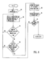
- FIG. 6 a flow chart shows how the system fixes spurious low oscillometric values in a table such as that shown in FIG. 4.
- Each table has a number of applied pressure step entries ranging from step 0 at the first step at the high applied pressure end of the table to step OSCPTR, the last entry at the low applied pressure end of the table.
- First a TEMP value equal to 1/2 the average value of all the non-zero oscillometric value entries in the table is calculated 60. Ignoring the zero step and the OSCPTR step the system begins with step No. 1 and determines which of its adjacent steps has the smaller oscillometric value (e.g., step 0 or step 2) 62. (In the case of FIG.
- step 2 is step 2. If the adjacent step with the smaller oscillometric value is less than the TEMP value then the current step being evaluated is not to be fixed 64. This is because most likely the low value occurs at a far end of the graph where it is likely not to be important.
- the value of the smaller valued adjacent step is larger than TEMP then the value of the current step is compared with 3/4 of the value of the smaller valued step 66. If the oscillometric value of the current step is smaller than this, then a decision is made to fix the value. If the current step is the second step or second to the last step then the oscillometric values of one step on each side of the current step are averaged together and the value assigned to the current step; otherwise, the values of the two steps on each side of the current step are averaged and the average value assigned to the current step in the table. See 68 and 70. In this way spurious lows are fixed. Using this method, the low values at steps 9 and 11 would be fixed indicated by the circles 72 and 74, while the values at steps 1, 3 and 4 would be left alone. When all the steps in the table are checked for fixing the system goes on to fix the high values 76.
- the end samples 0 and OSCPTR are ignored.
- the steps with the two largest oscillometric values are determined and they are checked to see how close together they are 80. For example, if they are adjacent then neither is to be considered an artifact and neither will be fixed. Where applied pressure bleed steps are small, e.g. 5 mbar, the criteria for determining whether an artifact exists or not could be different, e.g., if the two largest valued steps ire adjacent or only separated by one step then they are not to be considered artifacts.
- the larger valued adjacent step to the step with the largest oscillometric value is compared with one half the value of the largest valued step 82. If the value of the larger adjacent step is less than one half the largest value then the values of the steps on either side of the step with the largest value are averaged together and the average assigned to the step with the largest value 84. Following this the step with the largest peak is again found and the process is repeated.
- the adjusted table values are used for the determination of systolic and diastolic pressures within EVAL. If no systolic has been determined, the blood pressure control loop pumps up the pressure in the cuff (after a patient safety period has expired) to an applied pressure larger than before since it is assumed that the previous highest applied pressure wasn't high enough to measure systolic as described earlier. If the pressure bleeds below 106 mbar 50 or there is less than five seconds of measurement before time out 52 then the collect date and analyze loop and EVAL routine are repeated until a diastolic pressure is determined or until the applied pressure drops 20 mm.
- the FIX LO routine is performed before the FIX HI routine, otherwise normal values might be treated as spurious high values if the normal values are adjacent spurious low values.
- spurious low values are fixed first, the TEMP criteria 64 prevents the system from elevating normal low values next to a spurious high value.
Landscapes
- Health & Medical Sciences (AREA)
- Life Sciences & Earth Sciences (AREA)
- Vascular Medicine (AREA)
- Cardiology (AREA)
- Biomedical Technology (AREA)
- Molecular Biology (AREA)
- Physiology (AREA)
- Biophysics (AREA)
- Pathology (AREA)
- Engineering & Computer Science (AREA)
- Ophthalmology & Optometry (AREA)
- Heart & Thoracic Surgery (AREA)
- Medical Informatics (AREA)
- Physics & Mathematics (AREA)
- Surgery (AREA)
- Animal Behavior & Ethology (AREA)
- General Health & Medical Sciences (AREA)
- Public Health (AREA)
- Veterinary Medicine (AREA)
- Measuring Pulse, Heart Rate, Blood Pressure Or Blood Flow (AREA)
- Measuring Fluid Pressure (AREA)
Claims (18)
- Vorrichtung zur Messung des Blutdrucks umfassend:
eine Druckmanschette, die an einem Patienten in der Nähe eines Blutgefäßes befestigbar ist;
eine Einrichtung zum Verändern des Drucks in der Manschette, um einen Druck an den Patienten anzulegen;
eine Einrichtung, die mit der Manschette kommuniziert, zur Messung einer Meßgröße, welche den Blutdruck des Patienten repräsentiert;
eine Einrichtung zur Bildung einer Tabelle von Werten, welche von der genannten Meßgröße gebildet werden wenn der angelegte Druck verändert wird, wobei die Werte im allgemeinen von niedrigen Werten bei angelegten Drücken größer als der systolische Wert an einem Ende der Tabelle, hin zu einem Maximalwert bei angelegten Drücken zwischen dem systolischen und dem diastolischen Wert ansteigen, und die Werte im allgemeinen von niedrigen Werten bei einem angelegten Druck an einem gegenüberliegenden Ende der Tabelle, kleiner als der diastolische Wert zu dem genannten Maximalwert ansteigen;
gekennzeichnet durch
eine Einrichtung, die im Ansprechen auf vorbestimmte Kriterien Werte aus der genannten Tabelle als ungewünschte niedrige Störwerte auswählt, die eingestellt werden müssen, und die Einrichtung eine Bestimmungseinrichtung enthält, die bestimmt, welcher der Werte, die benachbart zu einem Prüfwert liegen, der kleinere ist, sowie eine Einrichtung zum Bereitstellen eines Schwellwertpegels, eine Einrichtung zum Vergleichen des kleineren Wertes mit dem genannten Schwellwertpegel, und, im Falle, daß der genannte kleinere Wert größer als der Schwellwertpegel ist, Auswählen des Prüfwerts als einen unerwünschten niedrigen Störwert, wenn der Prüfwert kleiner als ein vorgegebener Prozentanteil des kleineren Wertes ist, und
eine Einrichtung zum Korrigieren des unerwünschten niedrigen Störwertes auf einen neuen Wert. - Vorrichtung nach Anspruch 1, worin der vorbestimmte Prozentsatz 75 % beträgt.
- Vorrichtung nach Anspruch 1, weiterhin enthaltend eine Einrichtung zum Bereitstellen eines Schwellwertpegels und eine Einrichtung zum vergleichen des genannten kleineren Wertes mit dem genannten Schwellwertpegel, und worin die genannte Auswahleinrichtung den Prüfwert nicht als einen unerwünscht niedrigen Störwert auswählt, es sei denn, daß der kleinere Wert größer als der genannte Schwellwertpegel ist.
- Vorrichtung nach Anspruch 3, worin der vorbestimmte Schwellwertpegel in etwa die Hälfte des Mittelwertes von allen von Null verschiedenen Werten in der genannten Tabelle beträgt.
- Vorrichtung nach Anspruch 1, worin die genannte Korrektureinrichtung umfaßt:
eine Einrichtung zum Mitteln einer vorbestimmten Anzahl von Werten, welche sich benachbart zu einer Seite des Prüfwertes befinden, der als ein unerwünscht niedriger Störwert ausgewählt worden ist; und
eine Einrichtung zum Ersetzen jedes ausgewählten Prüfwertes durch den Mittelwert. - Vorrichtung zur Messung des Blutdrucks umfassend:
eine Druckmanschette, die an einem Patienten in der Nähe eines Blutgefäßes befestigbar ist;
eine Einrichtung zum Verändern des Drucks in der Manschette, um einen Druck an den Patienten anzulegen;
eine Einrichtung, die mit der Manschette kommuniziert, zur Messung einer Meßgröße, welche den Blutdruck des Patienten repräsentiert;
eine Einrichtung zur Bildung einer Tabelle von Werten, welche von der genannten Meßgröße gebildet werden wenn der angelegte Druck verändert wird, wobei die Werte im allgemeinen von niedrigen Werten bei angelegten Drücken größer als der systolische Wert an einem Ende der Tabelle, hin zu einem Maximalwert bei angelegten Drücken zwischen dem systolischen und dem diastolischen Wert ansteigen, und die Werte im allgemeinen von niedrigen Werten bei einem angelegten Druck an einem gegenüberliegenden Ende der Tabelle, kleiner als der diastolische Wert zu dem genannten Maximalwert ansteigen;
eine Einrichtung, die im Ansprechen auf vorbestimmte Kriterien Werte aus der Tabelle als unerwünscht hohe Störwerte auswählt, welche korrigiert werden müssen, dadurch gekennzeichnet, daß die genannte Einrichtung umfaßt:
eine Einrichtung zum Bestimmen der beiden höchsten Werte in der Tabelle;
eine Einrichtung zum Bestimmen des Abstandes der beiden höchsten Werte innerhalb der Tabelle;
eine Einrichtung zum Vergleichen des höchsten Wertes in der Tabelle mit dem benachbarten höheren Wert;
eine Einrichtung zum Bestimmen des höchsten Wertes als einen unerwünscht hohen Störwert, wenn die beiden höchsten Werte wenigstens einen vorbestimmten Abstand voneinander aufweisen und der höhere Wert, welcher sich benachbart zu dem genannten höchsten Wert befindet, kleiner als ein vorbestimmter Prozentsatz des höchsten Wertes ist; und
eine Einrichtung zum Ersetzen des unerwünscht hohen Störwertes durch einen neuen Wert. - Vorrichtung nach Anspruch 6, worin die Korrektureinrichtung umfaßt:
eine Einrichtung zum Mitteln einer vorbestimmten Anzahl von Werten, welche sich auf einer Seite von jedem Prüfwert befinden, der als unerwünscht hoher Störwert bestimmt worden ist; und
eine Einrichtung zum Ersetzten jedes Prüfwertes, der als ein unerwünscht hoher Störwert bestimmt worden ist, durch den genannten Mittelwert. - Vorrichtung nach Anspruch 6, worin der vorbestimmte Abstand darin besteht, daß die Werte nebeneinander liegen.
- Vorrichtung nach Anspruch 6, worin der vorbestimmte Prozentsatz 50 % beträgt.
- Verfahren zum Blutdruckmessen, welches die folgenden Schritte umfaßt:
Befestigen einer Druckmanschette an einem Patienten in der Nähe eines Blutgefäßes;
Verändern des Druckes in der Manschette, um einen Druck an den Patienten anzulegen;
Bereitstellen einer Kommunikation mit der Manschette, um eine Meßgröße zu messen, welche den Blutdruck des Patienten repräsentiert;
Bilden einer Tabelle von Werten, die aus der genannten Meßgröße abgeleitet werden, während der angelegte Druck verändert wird, wobei die Werte im allgemeinen von niedrigen angelegten Druckwerten größer als der systolische Wert an einem Ende der Tabelle auf einen Maximalwert des angelegten Drucks ansteigen, welcher sich zwischen dem systolischen und diastolischen Wert befindet, und die Werte im allgemeinen von niedrigen Werten bei angelegten Drücken kleiner als der diastolische Wert an dem gegenüberliegenden Ende der genannten Tabelle auf den Maximalwert ansteigen;
gekennzeichnet durch die folgenden Schritte:
Auswählen von Werten aus der genannten Tabelle als unerwünscht niedrige Störwerte, welche korrigiert werden müssen, durch Bestimmen, welcher der Werte, die sich benachbart zu einem Prüfwert befinden, der kleinere ist, Bereitstellen eines Schwellwertpegels, Vergleichen des kleineren Wertes mit dem genannten Schwellwertpegel und im Falle, daß der kleinere Wert größer als der genannte Schwellwertpegel ist, Auswählen des Prüfwertes als einen unerwünscht niedrigen Wert, es sei denn, daß der Prüfwert kleiner als ein vorbestimmter Prozentsatz des kleineren Wertes ist; und
Ersetzen des unerwünscht niedrigen Störwertes durch einen neuen Wert. - Verfahren nach Anspruch 10, worin der vorbestimmte Prozentsatz 75 % beträgt.
- Verfahren nach Anspruch 10, weiterhin umfassend die Schritte:
Bereitstellen eines Schwellwertpegels, Vergleichen des kleineren Wertes mit dem genannten Schwellwertpegel, und Nicht-Auswählen des Prüfwertes als einen unerwünscht niedrigen Wert, es sei denn, daß der kleinere Wert größer als der genannte Schwellwertpegel ist. - Verfahren nach Anspruch 12, worin der vorbestimmte Schwellwertpegel in etwa die Hälfte des Mittelwertes von allen von Null verschiedenen Werten der genannten Tabelle beträgt.
- Verfahren nach Anspruch 10, worin der Korrekturschritt umfaßt:
Mitteln einer vorbestimmten Anzahl von Werten, die sich auf einer Seite benachbart zu jedem Prüfwert befinden, der als ein unerwünscht niedriger Störwert bestimmt worden ist; und
Ersetzen jedes bestimmten Prüfwertes durch den genannten Mittelwert. - Verfahren zum Blutdruckmessen, welches die folgenden Schritte umfaßt:
Befestigen einer Druckmanschette an einem Patienten in der Nähe eines Blutgefäßes;
Verändern des Druckes in der Manschette, um einen Druck an den Patienten anzulegen;
Bereitstellen einer Kommunikation mit der Manschette, um eine Meßgröße zu messen, welche den Blutdruck des Patienten repräsentiert;
Bilden einer Tabelle von Werten, die aus der genannten Meßgröße abgeleitet werden, während der angelegte Druck verändert wird, wobei die Werte im allgemeinen von niedrigen angelegten Druckwerten größer als der systolische Wert an einem Ende der Tabelle auf einen Maximalwert des angelegten Drucks ansteigen, welcher sich zwischen dem systolischen und diastolischen Wert befindet, und die Werte im allgemeinen von niedrigen Werten bei angelegten Drücken kleiner als der diastolische Wert an dem gegenüberliegenden Ende der genannten Tabelle auf den Maximalwert ansteigen;
Auswählen von Werten aus der genannten Tabelle als unerwünscht hohe Störwerte, welche korrigiert werden müssen, gekennzeichnet durch die folgenden Schritte:
Bestimmen der beiden höchsten Werte in der Tabelle;
Bestimmen des Abstandes zwischen den beiden höchsten Werten innerhalb der Tabelle;
Vergleichen des höchsten Wertes in der Tabelle mit dem danebenliegenden größeren Wert;
Auswählen des höchsten Wertes als einen unerwünscht hohen Störwert, wenn die beiden höchsten Werte wenigstens einen vorbestimmten Abstand voneinander aufweisen und der größere Wert, welcher sich neben dem höchsten Wert befindet, kleiner als ein vorbestimmter Prozentsatz des höchsten Wertes ist; und
Ersetzen des unerwünscht hohen Störwertes durch einen neuen Wert. - Verfahren nach Anspruch 15, worin der Korrekturschritt umfaßt:
Mitteln einer vorbestimmten Anzahl von Werten, die sich benachbart auf einer Seite jedes Prüfwertes befinden, welcher als ein unerwünscht hoher Störwert ausgewählt worden ist; und
Ersetzen jedes Prüfwertes, welcher als ein unerwünscht hoher Störwert ausgewählt worden ist durch den genannten Mittelwert. - Verfahren nach Anspruch 15, worin der vorbestimmte Abstand darin besteht, daß die beiden Werte nebeneinander liegen.
- Verfahren nach Anspruch 15, worin der vorbestimmte Prozentsatz 50 % beträgt.
Priority Applications (1)
| Application Number | Priority Date | Filing Date | Title |
|---|---|---|---|
| AT87108807T ATE86461T1 (de) | 1986-06-17 | 1987-06-19 | Verfahren und geraet zur indirekten blutdruckmessung. |
Applications Claiming Priority (2)
| Application Number | Priority Date | Filing Date | Title |
|---|---|---|---|
| US06/875,440 US4799492A (en) | 1986-06-17 | 1986-06-17 | Method and apparatus for indirect blood pressure measurement |
| US875440 | 1986-06-17 |
Publications (3)
| Publication Number | Publication Date |
|---|---|
| EP0249990A2 EP0249990A2 (de) | 1987-12-23 |
| EP0249990A3 EP0249990A3 (en) | 1988-03-16 |
| EP0249990B1 true EP0249990B1 (de) | 1993-03-10 |
Family
ID=25365813
Family Applications (1)
| Application Number | Title | Priority Date | Filing Date |
|---|---|---|---|
| EP87108807A Expired - Lifetime EP0249990B1 (de) | 1986-06-17 | 1987-06-19 | Verfahren und Gerät zur indirekten Blutdruckmessung |
Country Status (6)
| Country | Link |
|---|---|
| US (1) | US4799492A (de) |
| EP (1) | EP0249990B1 (de) |
| JP (1) | JPS6365843A (de) |
| AT (1) | ATE86461T1 (de) |
| CA (1) | CA1299894C (de) |
| DE (1) | DE3784561T2 (de) |
Families Citing this family (12)
| Publication number | Priority date | Publication date | Assignee | Title |
|---|---|---|---|---|
| JP2664926B2 (ja) * | 1988-03-23 | 1997-10-22 | コーリン電子株式会社 | 血圧測定装置 |
| US4917098A (en) * | 1989-02-23 | 1990-04-17 | Colin Electronics Co., Ltd. | Method and apparatus for measuring blood pressure |
| JPH0719447Y2 (ja) * | 1989-07-13 | 1995-05-10 | オムロン株式会社 | 血圧計用カフの巻付機構 |
| US5069219A (en) * | 1989-12-20 | 1991-12-03 | Spacelabs, Inc. | Self snugging universal blood pressure cuff |
| US5054494A (en) * | 1989-12-26 | 1991-10-08 | U.S. Medical Corporation | Oscillometric blood pressure device |
| EP0808604B1 (de) * | 1991-02-15 | 2003-09-10 | Omron Corporation | Elektronisches Blutdruckmessgerät |
| US5522395A (en) * | 1991-05-01 | 1996-06-04 | Omron Corporation | Electronic sphygmomanometer and method of controlling operation of same |
| EP0585460B1 (de) * | 1991-05-01 | 1998-07-22 | Omron Corporation | Elektronischer blutdruckmesser und verfahren zur überwachung der funktion |
| US5201320A (en) * | 1991-06-13 | 1993-04-13 | Prevention Sciences Incorporated | Blood pressure measuring device |
| US5449288A (en) * | 1994-03-25 | 1995-09-12 | Hi-Z Technology, Inc. | Aspirated wick atomizer nozzle |
| US5542428A (en) * | 1995-03-23 | 1996-08-06 | Spacelabs Medical, Inc. | Method and apparatus for removing artifact encountered during automatic blood pressure measurements |
| US5800359A (en) * | 1995-05-19 | 1998-09-01 | Johnson & Johnson Medical, Inc. | NIBP playback system |
Family Cites Families (9)
| Publication number | Priority date | Publication date | Assignee | Title |
|---|---|---|---|---|
| US4263918A (en) * | 1977-03-21 | 1981-04-28 | Biomega Corporation | Methods of and apparatus for the measurement of blood pressure |
| US4190886A (en) * | 1978-04-10 | 1980-02-26 | Hewlett-Packard Company | Derivation of steady values of blood pressures |
| US4360029A (en) * | 1978-04-10 | 1982-11-23 | Johnson & Johnson | Automatic mean blood pressure reading device |
| US4420000A (en) * | 1981-09-28 | 1983-12-13 | Camino Laboratories, Inc. | Method and apparatus for measuring heartbeat rate |
| US4484584A (en) * | 1982-02-08 | 1984-11-27 | Nippon Colin Co., Ltd. | Method and apparatus for blood pressure measurement |
| US4461266A (en) * | 1982-04-29 | 1984-07-24 | Critikon, Inc. | Adaptive incremental blood pressure monitor |
| US4501280A (en) * | 1983-04-06 | 1985-02-26 | Critikon, Inc. | Automatic identification of cuff size in automated blood pressure monitors |
| US4669485A (en) * | 1984-02-17 | 1987-06-02 | Cortronic Corporation | Apparatus and method for continuous non-invasive cardiovascular monitoring |
| US4638810A (en) * | 1985-07-05 | 1987-01-27 | Critikon, Inc. | Automated diastolic blood pressure monitor with data enhancement |
-
1986
- 1986-06-17 US US06/875,440 patent/US4799492A/en not_active Expired - Fee Related
-
1987
- 1987-06-16 CA CA000539842A patent/CA1299894C/en not_active Expired - Fee Related
- 1987-06-17 JP JP62151042A patent/JPS6365843A/ja active Pending
- 1987-06-19 EP EP87108807A patent/EP0249990B1/de not_active Expired - Lifetime
- 1987-06-19 DE DE8787108807T patent/DE3784561T2/de not_active Expired - Fee Related
- 1987-06-19 AT AT87108807T patent/ATE86461T1/de not_active IP Right Cessation
Also Published As
| Publication number | Publication date |
|---|---|
| DE3784561D1 (de) | 1993-04-15 |
| EP0249990A2 (de) | 1987-12-23 |
| JPS6365843A (ja) | 1988-03-24 |
| EP0249990A3 (en) | 1988-03-16 |
| DE3784561T2 (de) | 1993-06-24 |
| US4799492A (en) | 1989-01-24 |
| CA1299894C (en) | 1992-05-05 |
| ATE86461T1 (de) | 1993-03-15 |
Similar Documents
| Publication | Publication Date | Title |
|---|---|---|
| US4777959A (en) | Artifact detection based on heart rate in a method and apparatus for indirect blood pressure measurement | |
| US5014714A (en) | Method and apparatus for distinguishing between accurate and inaccurate blood pressure measurements in the presence of artifact | |
| US5253648A (en) | Method and apparatus for excluding artifacts from automatic blood pressure measurements | |
| US5577508A (en) | Determination of oscillometric blood pressure by linear approximation | |
| EP0249990B1 (de) | Verfahren und Gerät zur indirekten Blutdruckmessung | |
| EP1195133B1 (de) | Oszillometrisches Blutdruckmessgerät mit verbesserter Verarbeitung in Gegenwart von Arrhythmie | |
| EP0207807B1 (de) | Gerät zur Überwachung des diastolischen Blutdruckes mit Daten-Aufbereitung | |
| US4774960A (en) | Method and apparatus for measuring blood pressure | |
| US4926873A (en) | Method for measuring blood pressure and apparatus for automated blood pressure measuring | |
| US5392781A (en) | Blood pressure monitoring in noisy environments | |
| US20050004477A1 (en) | Method and apparatus for measuring blood pressure using relaxed matching criteria | |
| US5072736A (en) | Non-invasive automatic blood pressure measuring apparatus | |
| US4677983A (en) | Method and apparatus for measuring circulatory function | |
| US4785820A (en) | Method and apparatus for systolic blood pressure measurement | |
| EP0379996B1 (de) | Verfahren und Vorrichtung zur Bestimmung des mittleren arteriellen Blutdruckes | |
| US5542428A (en) | Method and apparatus for removing artifact encountered during automatic blood pressure measurements | |
| CA1268641A (en) | Blood pressure measuring apparatus | |
| CA1181523A (en) | Blood pressure measurement with korotkov sound artifact information detection and rejection | |
| JPH0557850B2 (de) | ||
| OHTA et al. | A CIRCULATORY SYSTEM MONITOR INCLUDING AN ULTRAFILTRATION PRESSURE REGULATOR FOR ARTIFICIAL DIALYSIS | |
| JPH0480689B2 (de) | ||
| JPH02295543A (ja) | 自動血圧測定装置 |
Legal Events
| Date | Code | Title | Description |
|---|---|---|---|
| PUAI | Public reference made under article 153(3) epc to a published international application that has entered the european phase |
Free format text: ORIGINAL CODE: 0009012 |
|
| AK | Designated contracting states |
Kind code of ref document: A2 Designated state(s): AT BE CH DE FR GB IT LI LU NL SE |
|
| PUAL | Search report despatched |
Free format text: ORIGINAL CODE: 0009013 |
|
| RAP1 | Party data changed (applicant data changed or rights of an application transferred) |
Owner name: SPACELABS, INC. |
|
| AK | Designated contracting states |
Kind code of ref document: A3 Designated state(s): AT BE CH DE FR GB IT LI LU NL SE |
|
| 17P | Request for examination filed |
Effective date: 19880819 |
|
| 17Q | First examination report despatched |
Effective date: 19910205 |
|
| GRAA | (expected) grant |
Free format text: ORIGINAL CODE: 0009210 |
|
| AK | Designated contracting states |
Kind code of ref document: B1 Designated state(s): AT BE CH DE FR GB IT LI LU NL SE |
|
| PG25 | Lapsed in a contracting state [announced via postgrant information from national office to epo] |
Ref country code: IT Free format text: LAPSE BECAUSE OF FAILURE TO SUBMIT A TRANSLATION OF THE DESCRIPTION OR TO PAY THE FEE WITHIN THE PRESCRIBED TIME-LIMIT;WARNING: LAPSES OF ITALIAN PATENTS WITH EFFECTIVE DATE BEFORE 2007 MAY HAVE OCCURRED AT ANY TIME BEFORE 2007. THE CORRECT EFFECTIVE DATE MAY BE DIFFERENT FROM THE ONE RECORDED. Effective date: 19930310 Ref country code: NL Effective date: 19930310 Ref country code: AT Effective date: 19930310 Ref country code: BE Effective date: 19930310 Ref country code: SE Effective date: 19930310 |
|
| REF | Corresponds to: |
Ref document number: 86461 Country of ref document: AT Date of ref document: 19930315 Kind code of ref document: T |
|
| REF | Corresponds to: |
Ref document number: 3784561 Country of ref document: DE Date of ref document: 19930415 |
|
| ET | Fr: translation filed | ||
| PG25 | Lapsed in a contracting state [announced via postgrant information from national office to epo] |
Ref country code: LU Free format text: LAPSE BECAUSE OF NON-PAYMENT OF DUE FEES Effective date: 19930630 |
|
| NLV1 | Nl: lapsed or annulled due to failure to fulfill the requirements of art. 29p and 29m of the patents act | ||
| PLBE | No opposition filed within time limit |
Free format text: ORIGINAL CODE: 0009261 |
|
| STAA | Information on the status of an ep patent application or granted ep patent |
Free format text: STATUS: NO OPPOSITION FILED WITHIN TIME LIMIT |
|
| 26N | No opposition filed | ||
| PGFP | Annual fee paid to national office [announced via postgrant information from national office to epo] |
Ref country code: CH Payment date: 19950615 Year of fee payment: 9 |
|
| PGFP | Annual fee paid to national office [announced via postgrant information from national office to epo] |
Ref country code: FR Payment date: 19960515 Year of fee payment: 10 |
|
| PGFP | Annual fee paid to national office [announced via postgrant information from national office to epo] |
Ref country code: DE Payment date: 19960528 Year of fee payment: 10 |
|
| PGFP | Annual fee paid to national office [announced via postgrant information from national office to epo] |
Ref country code: GB Payment date: 19960529 Year of fee payment: 10 |
|
| PG25 | Lapsed in a contracting state [announced via postgrant information from national office to epo] |
Ref country code: LI Effective date: 19960630 Ref country code: CH Effective date: 19960630 |
|
| REG | Reference to a national code |
Ref country code: CH Ref legal event code: PL |
|
| PG25 | Lapsed in a contracting state [announced via postgrant information from national office to epo] |
Ref country code: GB Free format text: LAPSE BECAUSE OF NON-PAYMENT OF DUE FEES Effective date: 19970619 |
|
| GBPC | Gb: european patent ceased through non-payment of renewal fee |
Effective date: 19970619 |
|
| PG25 | Lapsed in a contracting state [announced via postgrant information from national office to epo] |
Ref country code: FR Free format text: LAPSE BECAUSE OF NON-PAYMENT OF DUE FEES Effective date: 19980227 |
|
| PG25 | Lapsed in a contracting state [announced via postgrant information from national office to epo] |
Ref country code: DE Free format text: LAPSE BECAUSE OF NON-PAYMENT OF DUE FEES Effective date: 19980303 |
|
| REG | Reference to a national code |
Ref country code: FR Ref legal event code: ST |
|
| REG | Reference to a national code |
Ref country code: FR Ref legal event code: ST |