EP0249893B1 - Device for the separation of a liquid and/or a gas from a mixture - Google Patents
Device for the separation of a liquid and/or a gas from a mixture Download PDFInfo
- Publication number
- EP0249893B1 EP0249893B1 EP87108460A EP87108460A EP0249893B1 EP 0249893 B1 EP0249893 B1 EP 0249893B1 EP 87108460 A EP87108460 A EP 87108460A EP 87108460 A EP87108460 A EP 87108460A EP 0249893 B1 EP0249893 B1 EP 0249893B1
- Authority
- EP
- European Patent Office
- Prior art keywords
- filter
- liquid
- particles
- retained
- vibration
- Prior art date
- Legal status (The legal status is an assumption and is not a legal conclusion. Google has not performed a legal analysis and makes no representation as to the accuracy of the status listed.)
- Expired - Lifetime
Links
- 239000007788 liquid Substances 0.000 title claims abstract description 24
- 239000000203 mixture Substances 0.000 title claims abstract description 13
- 238000000926 separation method Methods 0.000 title description 4
- 239000002245 particle Substances 0.000 claims abstract description 37
- 230000000717 retained effect Effects 0.000 claims abstract description 26
- 239000008246 gaseous mixture Substances 0.000 claims abstract description 5
- 239000007789 gas Substances 0.000 claims description 7
- 230000000694 effects Effects 0.000 claims description 5
- 238000005086 pumping Methods 0.000 claims description 4
- 230000001105 regulatory effect Effects 0.000 claims description 4
- 238000007599 discharging Methods 0.000 claims 1
- 230000010355 oscillation Effects 0.000 abstract description 10
- 238000000034 method Methods 0.000 abstract description 3
- 239000007787 solid Substances 0.000 abstract description 3
- 239000012071 phase Substances 0.000 description 7
- 230000014759 maintenance of location Effects 0.000 description 5
- 239000012065 filter cake Substances 0.000 description 3
- 239000012620 biological material Substances 0.000 description 2
- 239000000463 material Substances 0.000 description 2
- 102000004190 Enzymes Human genes 0.000 description 1
- 108090000790 Enzymes Proteins 0.000 description 1
- 238000009825 accumulation Methods 0.000 description 1
- 239000011942 biocatalyst Substances 0.000 description 1
- 230000015572 biosynthetic process Effects 0.000 description 1
- 238000004113 cell culture Methods 0.000 description 1
- 230000001276 controlling effect Effects 0.000 description 1
- 238000009295 crossflow filtration Methods 0.000 description 1
- 239000013013 elastic material Substances 0.000 description 1
- 239000004744 fabric Substances 0.000 description 1
- 238000001914 filtration Methods 0.000 description 1
- 239000012510 hollow fiber Substances 0.000 description 1
- 239000007791 liquid phase Substances 0.000 description 1
- 244000005700 microbiome Species 0.000 description 1
- 230000000149 penetrating effect Effects 0.000 description 1
- 230000035515 penetration Effects 0.000 description 1
- 239000011148 porous material Substances 0.000 description 1
Images
Classifications
-
- B—PERFORMING OPERATIONS; TRANSPORTING
- B01—PHYSICAL OR CHEMICAL PROCESSES OR APPARATUS IN GENERAL
- B01D—SEPARATION
- B01D46/00—Filters or filtering processes specially modified for separating dispersed particles from gases or vapours
- B01D46/24—Particle separators, e.g. dust precipitators, using rigid hollow filter bodies
- B01D46/2403—Particle separators, e.g. dust precipitators, using rigid hollow filter bodies characterised by the physical shape or structure of the filtering element
- B01D46/2407—Filter candles
-
- B—PERFORMING OPERATIONS; TRANSPORTING
- B01—PHYSICAL OR CHEMICAL PROCESSES OR APPARATUS IN GENERAL
- B01D—SEPARATION
- B01D29/00—Filters with filtering elements stationary during filtration, e.g. pressure or suction filters, not covered by groups B01D24/00 - B01D27/00; Filtering elements therefor
- B01D29/50—Filters with filtering elements stationary during filtration, e.g. pressure or suction filters, not covered by groups B01D24/00 - B01D27/00; Filtering elements therefor with multiple filtering elements, characterised by their mutual disposition
- B01D29/52—Filters with filtering elements stationary during filtration, e.g. pressure or suction filters, not covered by groups B01D24/00 - B01D27/00; Filtering elements therefor with multiple filtering elements, characterised by their mutual disposition in parallel connection
-
- B—PERFORMING OPERATIONS; TRANSPORTING
- B01—PHYSICAL OR CHEMICAL PROCESSES OR APPARATUS IN GENERAL
- B01D—SEPARATION
- B01D29/00—Filters with filtering elements stationary during filtration, e.g. pressure or suction filters, not covered by groups B01D24/00 - B01D27/00; Filtering elements therefor
- B01D29/62—Regenerating the filter material in the filter
- B01D29/70—Regenerating the filter material in the filter by forces created by movement of the filter element
- B01D29/72—Regenerating the filter material in the filter by forces created by movement of the filter element involving vibrations
-
- B—PERFORMING OPERATIONS; TRANSPORTING
- B01—PHYSICAL OR CHEMICAL PROCESSES OR APPARATUS IN GENERAL
- B01D—SEPARATION
- B01D35/00—Filtering devices having features not specifically covered by groups B01D24/00 - B01D33/00, or for applications not specifically covered by groups B01D24/00 - B01D33/00; Auxiliary devices for filtration; Filter housing constructions
- B01D35/20—Vibrating the filters
-
- B—PERFORMING OPERATIONS; TRANSPORTING
- B01—PHYSICAL OR CHEMICAL PROCESSES OR APPARATUS IN GENERAL
- B01D—SEPARATION
- B01D35/00—Filtering devices having features not specifically covered by groups B01D24/00 - B01D33/00, or for applications not specifically covered by groups B01D24/00 - B01D33/00; Auxiliary devices for filtration; Filter housing constructions
- B01D35/22—Directing the mixture to be filtered on to the filters in a manner to clean the filters
-
- B—PERFORMING OPERATIONS; TRANSPORTING
- B01—PHYSICAL OR CHEMICAL PROCESSES OR APPARATUS IN GENERAL
- B01D—SEPARATION
- B01D46/00—Filters or filtering processes specially modified for separating dispersed particles from gases or vapours
Definitions
- the invention relates to a device for separating liquid and / or gas from a liquid or gaseous mixture containing dispersed particles, comprising a container for holding the mixture, an essentially cylindrical sieve which is acted upon by the latter during operation and is impermeable to particles of a predetermined minimum size to be retained. or filter bodies and devices for removing the liquid or gases that pass through, the screen or filter bodies being connected to a vibration generator for generating a vibration with a direction of vibration parallel to the filter surface and arranged vertically in the container, the one, preferably arranged in the lower area, Has feed opening for the liquid and / or gaseous mixture and a discharge opening, preferably arranged in the upper region, for liquid and / or gas freed from the particles to be retained.
- Such a device is known from CH-A-602 162, in which, for the classification of solids suspended in liquids, a mixture in a boiler is fed to a vibrating sieve basket through which the liquid and the desired small particles pass while not suitable particles are retained by the sieve openings, the vibration of the sieve body being used to prevent the build-up of a filter cake.
- the filter residue settles in a conical part of the boiler and can be removed from there from time to time via a valve.
- the screen basket is designed as a hollow cylinder, the inner surface of which is closed and the outer surface of which is designed as a screen plate. Furthermore, it is alternatively provided that a finer fabric is applied to the screen plate in order to be able to retain smaller particles.
- those particles can pass through the sieve or filter surface whose particle size is smaller than the passage width of the sieve or filter openings.
- Such methods have the disadvantage, however, that the particles to be retained accumulate on the sieve or filter surface to form a filter cake, whereby they are partly forced into the through-openings by the liquid flow, so that the filter cake is required at relatively short intervals to be removed from the screen or filter surface and to adequately uncover its through openings.
- Attempts have been made to counteract these problems by various measures, for example so-called cross flow filtration, in which the mixture is passed parallel to the filter surface, whereby the liquid flow is intended to wash away the separated solids from the filter surface.
- WO-A-87/05322 (prior art under Art. 54 (3) EPC), which has also been published, discloses a filter device which is used in connection with biological materials and has a sieve surface with openings whose diameter is that of the particles to be retained exceeds. In order to produce a movement which prevents the particles to be retained from passing through the larger openings of the filter, the filter is excited to vibrate in the direction of its surface.
- DE-A-21 46 838 describes a filter device in which the liquid to be filtered is excited with an oscillator to vibrate at sound or ultrasonic frequencies.
- the liquid carries out vibrations parallel to the surface of the filter medium with a predetermined oscillation speed and an amplitude which is larger than the inner diameter of the pores of the filter medium, so that particles whose size is above a predetermined value are prevented from penetrating into the filter medium.
- the vibrations of the sieve or filter body result in a retention effect which is influenced in its extent by the oscillation amplitude and / or the oscillation frequency by the pressure waves which form in the area of the passage openings of the sieve or filter surface and which act in such a way on the particles to be retained. that, despite their smaller particle size relative to the through openings, they cannot escape through them.
- the vibrations largely prevent the formation of deposits on the screen or filter surface, thereby keeping the filtration resistance low as a result of the passage surface being free at all times. Due to the effective retention of particles smaller than the through openings, sieve or filter surfaces with much larger through openings can be selected for the separation, which enables a maximum flow.
- the container has feed and discharge openings each equipped with non-return valves, this also produces a pumping action by which the mixture to be separated is sucked in automatically and the separated liquid is automatically transported away.
- the device can be set quickly and easily to any mixture to be treated, it being possible in particular during operation to ensure an optimal course of the separation by appropriately regulating these parameters .
- Another important advantage is that, by stopping the vibration generator or by appropriately changing its vibration parameters, it is readily possible to remove the retention effect for the particles at any time with immediate effect or to reduce it to the desired extent.
- the device according to the invention has no rotating parts and no penetrations of rotating parts through standing walls, it is easy to sterilize and is therefore particularly suitable for biotechnological purposes.
- the device according to the invention has an essentially cylindrical container 1, which tapers conically in its lower region 2 and at its deepest point has a feed opening 3 for the mixture to be separated. At the upper end of the container 1 there is an outlet opening 4 for the liquid phase enriched with the particles to be retained.
- an essentially cylindrical sieve or filter body 5 is arranged, which consists of several sieve or filter tubes 14 connected to a common collecting space 15, the through openings 5 '' of which have a free passage width, which is the diameter of the particles to be retained exceeds.
- the sieve or filter body 5 passes through a cover 6 made of flexible material and can be set into vibrations by means of an oscillation generator 7, the oscillation amplitude and oscillation frequency of which can be set and regulated by means not shown.
- an oscillation generator 7 the oscillation amplitude and oscillation frequency of which can be set and regulated by means not shown.
- a discharge line 8 for the liquid freed of the particles to be retained.
- the lower region 5 'of the sieve or filter body 5 is spaced from the lower region 2 of the container 1 and is conical in the same sense as this.
- both the outer wall of the container 1 and the sieve or filter body 5 have a cylindrical shape in all the illustrated embodiments, this shape can be modified appropriately in various ways depending on the requirements of the individual case.
- a plurality of thin sieve or filter tubes 14 with parallel openings spaced parallel to one another are provided with through openings 5 ′′, the inner space of which is connected to a common collecting space 15 which is connected to the discharge opening 8 for the the phase to be retained communicates free phase.
- the lower ends of the sieve and filter tubes 14 are inserted into associated openings 17 of a plate 16, while their upper ends are closed by plugs 18.
- Such thin sieve or filter tubes 14 can also be so-called hollow fibers, which can be combined to form larger units (so-called multiple tube modules) and result in correspondingly large filter surfaces.
- the mixture to be separated is introduced into the container 1 via the inlet opening 3 and the sieve or filter body 5 is set into vibrations by means of the vibration generator 7 via the connecting rod 19 such that their amplitude and frequency prevent the particles to be retained from passing through the through openings of the sieve - or filter tubes 14 prevented.
- the phase freed from the particles to be retained can reach the interior of the sieve or filter tubes 14 through the passage openings (see arrows P).
- the phase freed from the particles to be retained is then discharged via the discharge opening 8.
- the phase enriched with the particles to be retained emerges from the container 1 via the discharge opening.
- the sieve or filter body 5 is suspended from the cover 6 made of elastic material, with no further support being often required within the container 1. Since the vibration amplitude transmitted via the connecting rod 19 does not exceed the elastic limit of the cover material, the connecting rod 19 can be firmly connected to the cover 6, so that only the discharge opening 8 for the phase freed from the particles to be retained must be passed tightly through the cover 6. This means that there is no need for a seal between a moving part and a stationary part, which is particularly important for devices to be operated in a sterile manner.
- the through openings 5 ′′ of the sieve or filter tubes 14 are each exaggerated in size and in reality only have a diameter of usually less than 100 ⁇ m.
- the vibration generator 7 has control devices (not shown) for setting and controlling both the frequency and the amplitude of the vibrations. As a result, the retention effect of the device can be adapted to the requirements.
- the vibrations of the sieve or filter body 5 also largely prevent the particles to be retained from settling on the sieve or filter body 5, so that the passage openings 5 ′′ remain free for the passage of the carrier phase.
Landscapes
- Chemical & Material Sciences (AREA)
- Chemical Kinetics & Catalysis (AREA)
- Physics & Mathematics (AREA)
- Geometry (AREA)
- Gas Separation By Absorption (AREA)
- Filtering Of Dispersed Particles In Gases (AREA)
- Combined Means For Separation Of Solids (AREA)
- Apparatus Associated With Microorganisms And Enzymes (AREA)
- Filtration Of Liquid (AREA)
- Separation Using Semi-Permeable Membranes (AREA)
- Separating Particles In Gases By Inertia (AREA)
Abstract
Description
Die Erfindung betrifft eine Vorrichtung zum Abscheiden von Flüssigkeit und/oder Gas aus einer dispergierte Teilchen enthaltenden, flüssigen oder gasförmigen Mischung, mit einem Behälter zur Aufnahme der Mischung, einem im Betrieb von dieser beaufschlagten, für zurückzuhaltende Teilchen vorbestimmter Mindestgröße undurchlässigen im wesentlichen zylindrischen Sieb- oder Filterkörper sowie Vorrichtungen zum Abführen der hindurchtretenden Flüssigkeit oder Gase, wobei der oder die Sieb- oder Filterkörper mit einem Schwingungserzeuger zur Erzeugung einer Vibration mit einer Schwingungsrichtung parallel zur Filterfläche verbunden und im Behälter senkrecht angeordnet sind, der eine, vorzugsweise im unteren Bereich angeordnete, Zuführöffnung für die flüssige und/oder gasförmige Mischung und eine, vorzugsweise im oberen Bereich angeordnete, Abführöffnung für von den zurückzuhaltenden Teilchen befreite Flüssigkeit und/oder Gas aufweist.The invention relates to a device for separating liquid and / or gas from a liquid or gaseous mixture containing dispersed particles, comprising a container for holding the mixture, an essentially cylindrical sieve which is acted upon by the latter during operation and is impermeable to particles of a predetermined minimum size to be retained. or filter bodies and devices for removing the liquid or gases that pass through, the screen or filter bodies being connected to a vibration generator for generating a vibration with a direction of vibration parallel to the filter surface and arranged vertically in the container, the one, preferably arranged in the lower area, Has feed opening for the liquid and / or gaseous mixture and a discharge opening, preferably arranged in the upper region, for liquid and / or gas freed from the particles to be retained.
Eine derartige Vorrichtung ist aus der CH-A-602 162 bekannt, bei der zum Klassieren von in Flüssigkeiten suspendierten Feststoffen eine Mischung in einem Kessel einem in Schwingungen versetzten Siebkorb zugeführt wird, durch den die Flüssigkeit und die erwünschten kleinen Teilchen hindurchtreten, während die nicht durch die Sieböffnungen passenden Teilchen zurückgehalten werden, wobei die Vibration des Siebkörpers den Aufbau eines Filterkuchens verhindern soll. Der Filterrückstand setzt sich in einem konischen Teil des Kessels ab und kann dort von Zeit zu Zeit über ein Ventil abgezogen werden. Der Siebkorb ist als Hohlzylinder ausgebildet, dessen Innenfläche geschlossen und dessen Außenfläche als Siebblech ausgebildet ist. Ferner ist alternativ vorgesehen, daß auf dem Siebblech ein feineres Gewebe aufgebracht wird, um auch kleinere Partikel zurückhalten zu können.Such a device is known from CH-A-602 162, in which, for the classification of solids suspended in liquids, a mixture in a boiler is fed to a vibrating sieve basket through which the liquid and the desired small particles pass while not suitable particles are retained by the sieve openings, the vibration of the sieve body being used to prevent the build-up of a filter cake. The filter residue settles in a conical part of the boiler and can be removed from there from time to time via a valve. The screen basket is designed as a hollow cylinder, the inner surface of which is closed and the outer surface of which is designed as a screen plate. Furthermore, it is alternatively provided that a finer fabric is applied to the screen plate in order to be able to retain smaller particles.
Auch bei anderen bekannten Sieb- oder Filterverfahren können jeweils diejenigen Teilchen durch die Sieb- oder Filterfläche hindurchtreten, deren Teilchengröße kleiner ist als die Durchgangsweite der Sieb- oder Filteröffnungen. Derartige Methoden haben jedoch den Nachteil, daß sich die zurückzuhaltenden Teilchen auf der Sieb- oder Filterfläche unter Bildung eine Filterkuchens ansammeln, wobei sie zum Teil durch die Flüssigkeitsströmung auch in die Durchgangsöffnungen hineingedrängt werden, so daß es in relativ kurzen Abständen erforderlich ist, den Filterkuchen von der Sieb- oder Filterfläche zu entfernen und deren Durchgangsöffnungen wieder hinreichend freizulegen. Man hat versucht, diesen Problemen durch verschiedene Maßnahmen, beispielsweise die sogenannte Querstromfiltration (Cross Flow Filtration) entgegenzuwirken, bei welcher die Mischung parallel zur Filterfläche an dieser vorbeigeführt wird, wodurch die Flüssigkeitsströmung jeweils die abgeschiedenen Feststoffe von der Filterfläche fortschwemmen soll. Stattdessen hat man auch versucht, die Sieb- und Filterfläche in Rotation zu versetzen, um dadurch deren Oberfläche von Belag weitgehend freizuhalten. Alle diese Maßnahmen haben jedoch nur begrenzte Wirksamkeit und sind insbesondere für viele biotechnologische Zwecke, beispielsweise Biokatalysatoren, wie Mikroorganismen, Zellkulturen, etc. enthaltende Mischungen wegen der auftretenden hohen Scherkräfte ungeeignet.In other known sieve or filter processes, those particles can pass through the sieve or filter surface whose particle size is smaller than the passage width of the sieve or filter openings. Such methods have the disadvantage, however, that the particles to be retained accumulate on the sieve or filter surface to form a filter cake, whereby they are partly forced into the through-openings by the liquid flow, so that the filter cake is required at relatively short intervals to be removed from the screen or filter surface and to adequately uncover its through openings. Attempts have been made to counteract these problems by various measures, for example so-called cross flow filtration, in which the mixture is passed parallel to the filter surface, whereby the liquid flow is intended to wash away the separated solids from the filter surface. Instead, attempts have also been made to set the screen and filter surface in rotation in order to largely keep their surface free of deposits. However, all of these measures have only limited effectiveness and are particularly unsuitable for many biotechnological purposes, for example mixtures containing biocatalysts, such as microorganisms, cell cultures, etc., because of the high shear forces that occur.
Aus der nachveröffentlichten WO-A-86/07284 (Stand der Technik nach Art. 54(3) EPÜ) ist ein Filterkörper bekannt, der insbesondere zur Verwendung bei biologischen Materialien vorgesehen ist und dessen Filterfläche in Vibrationen versetzt wird, so daß Partikelgrößen zurückgehalten werden, für die der Filterkörper in Ruhe durchlässig wäre. Der Filterkörper wird dabei in Richtung seiner Oberfläche bewegt.From the post-published WO-A-86/07284 (prior art according to Art. 54 (3) EPC) a filter body is known which is intended in particular for use with biological materials and whose filter surface is set in vibration so that particle sizes are retained for which the filter body would be permeable at rest. The filter body is moved in the direction of its surface.
Die ebenfalls nachveröffentlichte WO-A-87/05322 (Stand der Technik nach Art. 54(3)EPÜ) offenbart eine Filtervorrichtung, die im Zusammenhang mit biologischen Materialien benutzt wird und eine Siebfläche mit Öffnungen aufweist, deren Durchmesser den der zurückzuhaltenden Teilchen übersteigt. Zur Erzeugung einer den Durchtritt der zurückzuhaltenden Teilchen durch die größeren Öffnungen des Filters verhindernden Bewegung wird das Filter in Richtung seiner Oberfläche zu Schwingungen angeregt.WO-A-87/05322 (prior art under Art. 54 (3) EPC), which has also been published, discloses a filter device which is used in connection with biological materials and has a sieve surface with openings whose diameter is that of the particles to be retained exceeds. In order to produce a movement which prevents the particles to be retained from passing through the larger openings of the filter, the filter is excited to vibrate in the direction of its surface.
Die DE-A-21 46 838 beschreibt eine Filtervorrichtung, bei der die zu filtrierende Flüssigkeit mit einem Oszillator zu Schwingungen mit Schall- oder Ultraschallfrequenzen angeregt wird. Die Flüssigkeit führt parallel zur Oberfläche des Filtermediums Schwingungen mit vorbestimmter Schwingungsgeschwindigkeit und einer Amplitude aus, die größer als der Innendurchmesser der Poren des Filtermediums ist, so daß Teilchen, deren Größe über einem vorbestimmten Wert liegt, daran gehindert sind, in das Filtermedium einzudringen.DE-A-21 46 838 describes a filter device in which the liquid to be filtered is excited with an oscillator to vibrate at sound or ultrasonic frequencies. The liquid carries out vibrations parallel to the surface of the filter medium with a predetermined oscillation speed and an amplitude which is larger than the inner diameter of the pores of the filter medium, so that particles whose size is above a predetermined value are prevented from penetrating into the filter medium.
Aufgabe der Erfindung ist es daher, ausgehend von der CH-A-602 162 eine Vorrichtung zu schaffen, die ohne Verstopfungen ein wirksames Abscheiden von Flüssigkeit und/oder Gas unter weitestgehender, leicht regel- und aufhebbarer Zurückhaltung dispergierter Teilchen ermöglicht.It is therefore the object of the invention, starting from CH-A-602 162, to provide a device which, without clogging, enables the effective separation of liquid and / or gas with the greatest possible, easily controllable and removable retention of dispersed particles.
Die Aufgabe wird durch die im kennzeichnenden Teil von Anspruch 1 angeführten Merkmale gelöst.The object is achieved by the features stated in the characterizing part of
Bei der erfindungsgemäßen Vorrichtung entsteht durch die Schwingungen des Sieb- oder Filterkörpers ein in seinem Ausmaß von der Schwingungsamplitude und/oder der Schwingungsfrequenz beeinflußter Rückhalteeffekt durch die sich im Bereich der Durchgangsöffnungen der Sieb- oder Filterfläche ausbildenden Druckwellen, welches auf die zurückzuhaltenden Teilchen derart einwirken, daß sie trotz ihrer relativ zu den Durchgangsöffnungen kleineren Teilchengröße nicht durch diese hindurch austreten können. Außerdem werden durch die Schwingungen Belagsbildungen an der Sieb- oder Filterfläche weitgehend verhindert und dadurch infolge der jederzeit freien Durchgangsfläche der Filtrationswiderstand niedriggehalten. Durch die wirksame Zurückhaltung von gegenüber den Durchgangsöffnungen kleineren Teilchen können für die Abscheidung Sieb- oder Filterflächen mit sehr viel größeren Durchgangsöffnungen gewählt werden, was einen maximalen Durchfluß ermöglicht.In the device according to the invention, the vibrations of the sieve or filter body result in a retention effect which is influenced in its extent by the oscillation amplitude and / or the oscillation frequency by the pressure waves which form in the area of the passage openings of the sieve or filter surface and which act in such a way on the particles to be retained. that, despite their smaller particle size relative to the through openings, they cannot escape through them. In addition, the vibrations largely prevent the formation of deposits on the screen or filter surface, thereby keeping the filtration resistance low as a result of the passage surface being free at all times. Due to the effective retention of particles smaller than the through openings, sieve or filter surfaces with much larger through openings can be selected for the separation, which enables a maximum flow.
Einbauten im Innenraum der Sieb- oder Filterkörpers, beispielsweise Querscheiben, mit sich in Richtung zur Abführöffnung verengenden Durchlässen erzielen eine Pumpwirkung, welche die von den zurückzuhaltenden Teilchen befreite Flüssigkeit schneller von der Austrittsseite der Sieb- oder Filterfläche wegfördert.Internals in the interior of the sieve or filter body, for example transverse disks, with passages narrowing in the direction of the discharge opening achieve a pumping action which conveys the liquid freed of the particles to be retained more quickly from the outlet side of the sieve or filter surface.
Vorteilhafte weitere Ausführungsformen dieser Vorrichtung sind in den Unteransprüchen 2 bis 3 beschrieben.Advantageous further embodiments of this device are described in subclaims 2 to 3.
Wenn der Behälter jeweils mit Rückschlagventilen ausgestattete Zuführ- und Abführöffnungen aufweist, wird hierdurch ebenfalls eine Pumpwirkung erzielt, durch die das aufzutrennende Gemisch selbsttätig angesaugt und die abgeschiedene Flüssigkeit selbsttätig abtransportiert wird.If the container has feed and discharge openings each equipped with non-return valves, this also produces a pumping action by which the mixture to be separated is sucked in automatically and the separated liquid is automatically transported away.
Wenn die Schwingungsamplitude und/oder die Schwingungsfrequenz des Schwingungserzeugers einstell- und regelbar ist, kann die Vorrichtung rasch und einfach auf jede zu behandelnde Mischung eingestellt werden, wobei es insbesondere während des Betriebes möglich ist, durch zweckentsprechende Regelung dieser Parameter einen optimalen Verlauf der Abscheidung sicherzustellen. Ein wichtiger Vorteil besteht auch darin, daß es durch Stillsetzen des Schwingungserzeugers oder durch geeignete Veränderung seiner Schwingungsparameter ohne weiteres möglich ist, die Rückhaltewirkung für die Teilchen jederzeit mit sofortiger Wirkung aufzuheben oder auf das gewünschte Ausmaß zu vermindern.If the oscillation amplitude and / or the oscillation frequency of the oscillation generator can be set and regulated, the device can be set quickly and easily to any mixture to be treated, it being possible in particular during operation to ensure an optimal course of the separation by appropriately regulating these parameters . Another important advantage is that, by stopping the vibration generator or by appropriately changing its vibration parameters, it is readily possible to remove the retention effect for the particles at any time with immediate effect or to reduce it to the desired extent.
Da die erfindungsgemäße Vorrichtung keine drehenden Teile und keine Durchführungen drehender Teile durch stehende Wandungen aufweist, ist sie leicht sterilisierbar und dadurch für biotechnologische Zwecke besonders geeignet.Since the device according to the invention has no rotating parts and no penetrations of rotating parts through standing walls, it is easy to sterilize and is therefore particularly suitable for biotechnological purposes.
Im folgenden wird eine bevorzugte Ausführungsform der Vorrichtung unter Bezugnahme auf die beigefügten Zeichnungen weiter erläutert. Es zeigen:
- Fig. 1
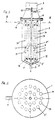
- - einen schematischen Vertikalschnitt durch eine Ausführungsform der Vorrichtung und
- Fig. 2
- - einen Querschnitt längs der Linie IV-IV der Fig. 1.
- Fig. 1
- - A schematic vertical section through an embodiment of the device and
- Fig. 2
- - A cross section along the line IV-IV of Fig. 1st
Die erfindungsgemäße Vorrichtung weist einen im wesentlichen zylindrischen Behälter 1 auf, der in seinem unteren Bereich 2 konisch zuläuft und an dessen tiefster Stelle eine Zuführöffnung 3 für die zu trennende Mischung aufweist. Am oberen Ende des Behälters 1 ist eine Ablauföffnung 4 für die mit den zurückzuhaltenden Teilchen angereichert flüssige Phase angebracht. Im Innenraum des Behälters 1 ist ein im wesentlichen zylindrischer Sieb- oder Filterkörper 5 angeordnet, welcher aus mehreren, an einem gemeinsamen Sammelraum 15 angeschlossenen Sieb- oder Filterrohren 14 besteht, deren Durchgangsöffnungen 5'' eine freie Durchgangsweite aufweisen, die den Durchmesser der zurückzuhaltenden Teilchen übersteigt. Der Sieb- oder Filterkörper 5 durchsetzt einen Deckel 6 aus flexiblem Material und ist mittels eines Schwingungserzeugers 7 in Schwingungen versetzbar, deren Schwingungsamplitude und Schwingungsfrequenz durch nicht dargestellte Vorrichtungen einstell- und regelbar sind. Im Inneren des Sieb- oder Filterkörpers 5 ist ferner eine Abführleitung 8 für die von den zurückzuhaltenden Teilchen befreite Flüssigkeit angeordnet. Der untere Bereich 5' des Sieb- oder Filterkörpers 5 ist vom unteren Bereich 2 des Behälters 1 beabstandet und in gleichem Sinne konisch ausgebildet, wie dieser.The device according to the invention has an essentially
Während bei allen dargestellten Ausführungsformen sowohl die Außenwand des Behälters 1, als auch der Sieb- oder Filterkörper 5 eine zylindrische Form aufweisen, kann diese Form je nach den Anforderungen des Einzelfalles in verschiedener Weise zweckentsprechend abgewandelt sein.While both the outer wall of the
Bei der in den Fig. 1 und 2 dargestellten Ausführungsform sind mehrere in Abständen voneinander parallel verlaufende, dünne Sieb- oder Filterrohre 14 mit Durchgangsöffnungen 5'' vorgesehen, deren Inneneraum mit einem gemeinsamen Sammelraum 15 verbunden ist, der mit der Abführöffnung 8 für die von den zurückzuhaltenden Teilchen freie Phase kommuniziert. Dabei sind die unteren Enden der Sieb- und Filterrohre 14 in zugehörige Öffnungen 17 einer Platte 16 eingefügt, während ihre oberen Enden durch Stopfen 18 verschlossen sind. Derartige dünne Sieb- oder Filterrohre 14 können auch sog. Hohlfasern sein, welche zu größeren Einheiten (sog. Mehrfach-Rohrmodulen) gebündelt zusammengefaßt sein können und entsprechende große Filteroberflächen ergeben.In the embodiment shown in FIGS. 1 and 2, a plurality of thin sieve or
Zum Betrieb wird die aufzutrennende Mischung über die Zulauföffnung 3 in den Behälter 1 eingebracht und der Sieb- oder Filterkörper 5 mittels des Schwingungserzeugers 7 über die Verbindungsstange 19 in solche Schwingungen versetzt, daß deren Amplitude und Frequenz den Durchtritt der zurückzuhaltenden Teilchen durch die Durchgangsöffnungen der Sieb- oder Filterrohre 14 verhindert.For operation, the mixture to be separated is introduced into the
Es kommt damit zu einer Anreicherung der zurückzuhaltenden Teilchen in dem Raum zwischen der Innenwand des Behälters 1 und dem Sieb- bzw. Filterkörper 5. Die von den zurückzuhaltenden Teilchen befreite Phase kann jedoch durch die Durchtrittsöffnungen hindurch in das Innere der Sieb- oder Filterrohre 14 gelangen (siehe Pfeile P). Die von den zurückzuhaltenden Teilchen befreite Phase wird dann über die Abführöffnung 8 abgeführt. Die mit den zurückzuhaltenden Teilchen angereicherte Phase tritt über die Abführöffnung aus dem Behälter 1 aus.This results in an accumulation of the particles to be retained in the space between the inner wall of the
Einbauten im Innenraum der Sieb- oder Filterkörpers, beispielsweise Querscheiben, mit sich in Richtung zur Abfuhröffnung verengenden Durchlässen erzielen eine Pumpwirkung, welche die von den zurückzuhaltenden Teilchen befreite Flüssigkeit schneller von der Austrittsseite der Sieb- oder Filterfläche wegfördert. Rückschlagventile verhindern dabei ein Rückpumpen der Mischung in die Zuführöffnung 3 bzw. ein Rücksaugen aus den Abführöffnungen 4 und 8.Internals in the interior of the sieve or filter body, for example transverse disks, with passages narrowing in the direction of the discharge opening achieve a pumping action which conveys the liquid freed of the particles to be retained more quickly from the outlet side of the sieve or filter surface. Check valves prevent the mixture from being pumped back into the feed opening 3 or from being sucked back out of the
Bei der dargestellten Ausführungsform ist der Sieb- oder Filterkörper 5 an dem aus elastischem Material gefertigten Deckel 6 aufgehängt, wobei innerhalb des Behälters 1 vielfach keine weitere Stützung mehr erforderlich ist. Da die über die Verbindungsstange 19 übertragene Schwinungsamplitude die Elastizitätsgrenze des Deckelmaterials nicht übersteigen, kann die Verbindungsstange 19 mit dem Deckel 6 fest verbunden sein, daß lediglich die Abführöffnung 8 für die von den zurückzuhaltenden Teilchen befreite Phase dicht durch den Deckel 6 hindurchgeführt werden muß. Damit bedarf es keiner Dichtung zwischen einem bewegten und einem stillstehenden Teil, was insbesondere für steril zu betreibende Vorrichtungen wesentlich ist.In the embodiment shown, the sieve or
Die Durchgangsöffnungen 5'' der Sieb- oder Filterrohre 14 sind jeweils übertrieben groß dargestellt und haben in Wirklichkeit nur einen Durchmesser von meist unter 100 µm. Infolge der Schwingungen des Sieb- oder Filterkörpers werden dabei Teilchen zurückgehalten, deren Durchmesser noch erheblich geringer sind, als die Durchgangsweite der Durchgangsöffnungen 5''. Der Schwingungserzeugar 7 besitzt nicht dargestellte Regelvorrichtungen zur Einstellung und Regelung sowohl der Frequenz als auch der Amplitude der Schwingungen. Hierdurch kann die Rückhaltewirkung der Vorrichtung den Erfordernissen zweckentsprechend angepaßt werden. Durch die Schwingungen des Sieb- oder Filterkörpers 5 wird auch das Absetzen der zurückzuhaltenden Teilchen am Sieb- bzw. Filterkörper 5 weitgehend verhindert, so daß die Druchgangsöffnungen 5'' für den Durchgang der Trägerphase freibleiben.The through
Claims (3)
- A device for separating liquid and/or gas from a liquid or gaseous mixture containing dispersed particles, comprising a container (1) which accommodates the mixture, a substantially cylindrical screening- or filter body (5) which during operation is acted upon by said mixture and which is impermeable to particles of a predetermined minimum size which are to be retained, and devices for discharging the liquid or gases which pass through, where the screening- or filter body or bodies (5) is/are connected to a vibration generator (7) which generates a vibration with a direction of vibration parallel to the filter surface and is/are arranged perpendicularly in the container (1), which container comprises a supply opening (3), preferably arranged in the lower region (2), for the liquid and/or gaseous mixture and a discharge opening (8), preferably arranged in the upper region, for liquid and/or gas freed of the particles to be retained, characterised in that the screening- or filter body (5) consists of a plurality of parallel screening- or filter tubes (14) arranged at intervals from one another, which are connected at one end to a common collecting chamber (15) and in their interior are provided with built-in components (9) which serve to produce a pumping effect and which contain through-holes (10) which narrow in the direction of the discharge opening (8), where the screening- or filter tubes (14) can be set by the vibration generator in vibrations which at least substantially prevent the passage of the particles which are to be retained through the comparatively larger holes (5'').
- A device as claimed in Claim 1, characterised in that the supply opening (3) and/or the discharge opening (8) are provided with a non-return valve (11, 12, 13).
- A device as claimed in Claim 1, 2 or 3, characterised in that the vibration generator (7) is provided with devices for adjusting and regulating the vibration amplitude and/or the vibration frequency.
Applications Claiming Priority (2)
| Application Number | Priority Date | Filing Date | Title |
|---|---|---|---|
| AT1648/86 | 1986-06-17 | ||
| AT0164886A AT386965B (en) | 1986-06-17 | 1986-06-17 | DEVICE FOR SEPARATING LIQUID AND / OR GAS FROM A FLOATING LIQUID OR A FLUID-GAS MIXTURE |
Publications (3)
| Publication Number | Publication Date |
|---|---|
| EP0249893A2 EP0249893A2 (en) | 1987-12-23 |
| EP0249893A3 EP0249893A3 (en) | 1988-07-27 |
| EP0249893B1 true EP0249893B1 (en) | 1993-03-17 |
Family
ID=3517965
Family Applications (1)
| Application Number | Title | Priority Date | Filing Date |
|---|---|---|---|
| EP87108460A Expired - Lifetime EP0249893B1 (en) | 1986-06-17 | 1987-06-11 | Device for the separation of a liquid and/or a gas from a mixture |
Country Status (6)
| Country | Link |
|---|---|
| US (1) | US4828719A (en) |
| EP (1) | EP0249893B1 (en) |
| JP (1) | JPS63185418A (en) |
| AT (2) | AT386965B (en) |
| DE (1) | DE3784782D1 (en) |
| ES (1) | ES2038972T3 (en) |
Families Citing this family (5)
| Publication number | Priority date | Publication date | Assignee | Title |
|---|---|---|---|---|
| AT386837B (en) * | 1986-03-06 | 1988-10-25 | Chemap Ag | DEVICE FOR CULTIVATING BIO CATALYSTS |
| US5098584A (en) * | 1990-08-31 | 1992-03-24 | City Management Corporation | Method for separating oils from scum |
| GB0913318D0 (en) | 2009-07-31 | 2009-09-02 | Univ Loughborough | Process |
| US20140251143A1 (en) * | 2013-03-08 | 2014-09-11 | Donaldson Company, Inc. | Filtration system for a gas turbine air intake and methods |
| DE102017212768A1 (en) * | 2017-07-25 | 2019-01-31 | Robert Bosch Gmbh | Liquid filter and tank filter system with a liquid filter |
Citations (3)
| Publication number | Priority date | Publication date | Assignee | Title |
|---|---|---|---|---|
| CH602162A5 (en) * | 1976-11-10 | 1978-07-31 | Chemap Ag | Sepn. of solids suspended in liq. |
| WO1986007284A1 (en) * | 1985-06-12 | 1986-12-18 | Public Health Laboratory Service Board | Improvements in filters |
| WO1987005322A1 (en) * | 1986-03-06 | 1987-09-11 | Chemap Ag | Method and device for the treatment of a liquid mixture containing a biocatalyst or similar particles |
Family Cites Families (16)
| Publication number | Priority date | Publication date | Assignee | Title |
|---|---|---|---|---|
| CA535572A (en) * | 1957-01-08 | W. Ziegenbusch Carl | Treatment of thixotropic materials | |
| FR1130754A (en) * | 1955-08-22 | 1957-02-12 | Telescopic filter and refinement to fabric sleeve filters | |
| US3002915A (en) * | 1958-08-18 | 1961-10-03 | Exxon Research Engineering Co | Filtration method |
| DE1461460A1 (en) * | 1964-08-04 | 1969-04-10 | Reiter Dipl Ing Anton | Internally pressurized tube bundle filter with vertical fixed or detachable filter inserts and vibration device |
| US3478883A (en) * | 1967-04-13 | 1969-11-18 | Amsalco Inc | Acoustic filtration apparatus |
| BR6806687D0 (en) * | 1968-02-26 | 1973-04-12 | P Strojirny | PERFECTED VIBRATILE SCREEN FOR CLASSIFICATION OF LIQUID SUSPENSIONS AND SOLID MATERIALS |
| JPS548906B1 (en) * | 1969-05-21 | 1979-04-19 | ||
| US3622004A (en) * | 1969-11-06 | 1971-11-23 | Chandler Evans Inc | Recirculating wash flow filter |
| US3664507A (en) * | 1970-04-15 | 1972-05-23 | Selas Corp Of America | Filter tubes in a resilient holder |
| US3766059A (en) * | 1970-12-28 | 1973-10-16 | Toshin Science Co | Filtering method and a filtering machine therefor |
| DE2225057A1 (en) * | 1971-12-27 | 1973-07-12 | Dover Corp | FILTER |
| JPS5126665A (en) * | 1974-08-29 | 1976-03-05 | Kinzoku Giken Kk | Tetsu oyobi tetsugokintodotono tantsukigokin |
| SU695677A1 (en) * | 1976-10-07 | 1979-11-05 | Всесоюзный Государственный Ордена Трудового Красного Знамени Головной Проектно-Изыскательский И Научно-Исследовательский Институт "Гипроводхоз" | Acoustic filter |
| US4136035A (en) * | 1977-07-26 | 1979-01-23 | Bogomolov Boris N | Apparatus for dehydration of continuously fed flow of suspension |
| CH625130A5 (en) * | 1977-11-08 | 1981-09-15 | Chemap Ag | Process for filtration with the addition of filter aids and use thereof |
| US4267039A (en) * | 1977-12-05 | 1981-05-12 | Ecodyne Corporation | Fluid filtration method and apparatus |
-
1986
- 1986-06-17 AT AT0164886A patent/AT386965B/en not_active IP Right Cessation
-
1987
- 1987-06-11 AT AT87108460T patent/ATE86876T1/en active
- 1987-06-11 ES ES198787108460T patent/ES2038972T3/en not_active Expired - Lifetime
- 1987-06-11 DE DE8787108460T patent/DE3784782D1/en not_active Expired - Fee Related
- 1987-06-11 EP EP87108460A patent/EP0249893B1/en not_active Expired - Lifetime
- 1987-06-17 US US07/063,254 patent/US4828719A/en not_active Expired - Lifetime
- 1987-06-17 JP JP62152390A patent/JPS63185418A/en active Pending
Patent Citations (3)
| Publication number | Priority date | Publication date | Assignee | Title |
|---|---|---|---|---|
| CH602162A5 (en) * | 1976-11-10 | 1978-07-31 | Chemap Ag | Sepn. of solids suspended in liq. |
| WO1986007284A1 (en) * | 1985-06-12 | 1986-12-18 | Public Health Laboratory Service Board | Improvements in filters |
| WO1987005322A1 (en) * | 1986-03-06 | 1987-09-11 | Chemap Ag | Method and device for the treatment of a liquid mixture containing a biocatalyst or similar particles |
Also Published As
| Publication number | Publication date |
|---|---|
| EP0249893A2 (en) | 1987-12-23 |
| EP0249893A3 (en) | 1988-07-27 |
| US4828719A (en) | 1989-05-09 |
| JPS63185418A (en) | 1988-08-01 |
| DE3784782D1 (en) | 1993-04-22 |
| ATE86876T1 (en) | 1993-04-15 |
| ATA164886A (en) | 1988-04-15 |
| AT386965B (en) | 1988-11-10 |
| ES2038972T3 (en) | 1993-08-16 |
Similar Documents
| Publication | Publication Date | Title |
|---|---|---|
| EP0262398B1 (en) | Pre-coat filter | |
| EP1592489B1 (en) | Filtering device and filtration method | |
| DE2323996A1 (en) | DEVICE AND METHOD FOR SEPARATING THE CARRIER LIQUID FROM PARTICLES SUSPENDED IN IT | |
| DE3117712A1 (en) | Process and apparatus for the pressure filtration of a filtrate | |
| DE3023886A1 (en) | METHOD AND DEVICE FOR MACHINING AND PROCESSING MATERIALS, ESPECIALLY FLOWABLE SOLID MATERIAL MIXTURES AND DISPERSIONS, BY VIBRATING TOOLS | |
| DE1507839A1 (en) | Method and device for cleaning filter media | |
| EP2185262B1 (en) | Pressure filter with vibrator | |
| DE2146838C3 (en) | Method and device for filtering liquids | |
| EP0249893B1 (en) | Device for the separation of a liquid and/or a gas from a mixture | |
| DE69932005T2 (en) | Apparatus and method for the regeneration of fluids for liquid treatment | |
| DE2449817A1 (en) | PROCESS AND EQUIPMENT FOR FILTRATION OF SUSPENSIONS | |
| DE102005027509B4 (en) | Device and filter element for filtering fluid-solid mixtures | |
| DE3782742T2 (en) | METHOD AND DEVICE FOR REGENERATING A DYNAMIC MEMBRANE IN A LIQUID SEPARATOR. | |
| EP4245395B1 (en) | Device and method for continuous gas exchange in a flow of a fluid mixture | |
| EP0465840A1 (en) | Filtering device, especially for the separation of coarse particles from a lubricant suspension and use thereof | |
| EP0087040A2 (en) | Vibrant separator for an agitator ball mill | |
| DE1303735C2 (en) | PROCEDURE FOR CONTINUOUS CLASSIFICATION, FILTRATION, OR FRACTIONATION OF SUSPENSIONS OR SOLID-LOADED GASES UNDER PRESSURE AND DEVICE FOR USE | |
| DE10047431B4 (en) | Pressure filter with vibration drive | |
| DE3605065A1 (en) | Separation apparatus | |
| CH602162A5 (en) | Sepn. of solids suspended in liq. | |
| DE19528775C1 (en) | Filter assembly for separating dispersed solids of liquids from liquid | |
| DE1442538C2 (en) | Process for the continuous classification, filtration or fractionation of suspensions or solids-laden gases under pressure and the device used for this purpose | |
| EP1877155A1 (en) | Process and device for separating solids and liquids | |
| DE9417638U1 (en) | Candle filter device for beer filtration | |
| DE10108394C2 (en) | Ceramic filter element for particle separation from hot gases |
Legal Events
| Date | Code | Title | Description |
|---|---|---|---|
| PUAI | Public reference made under article 153(3) epc to a published international application that has entered the european phase |
Free format text: ORIGINAL CODE: 0009012 |
|
| AK | Designated contracting states |
Kind code of ref document: A2 Designated state(s): AT BE CH DE ES FR GB IT LI NL SE |
|
| PUAL | Search report despatched |
Free format text: ORIGINAL CODE: 0009013 |
|
| AK | Designated contracting states |
Kind code of ref document: A3 Designated state(s): AT BE CH DE ES FR GB IT LI NL SE |
|
| 17P | Request for examination filed |
Effective date: 19880910 |
|
| 17Q | First examination report despatched |
Effective date: 19900913 |
|
| RTI1 | Title (correction) | ||
| GRAA | (expected) grant |
Free format text: ORIGINAL CODE: 0009210 |
|
| ITF | It: translation for a ep patent filed | ||
| AK | Designated contracting states |
Kind code of ref document: B1 Designated state(s): AT BE CH DE ES FR GB IT LI NL SE |
|
| REF | Corresponds to: |
Ref document number: 86876 Country of ref document: AT Date of ref document: 19930415 Kind code of ref document: T |
|
| GBT | Gb: translation of ep patent filed (gb section 77(6)(a)/1977) |
Effective date: 19930324 |
|
| REF | Corresponds to: |
Ref document number: 3784782 Country of ref document: DE Date of ref document: 19930422 |
|
| ET | Fr: translation filed | ||
| PG25 | Lapsed in a contracting state [announced via postgrant information from national office to epo] |
Ref country code: LI Effective date: 19930630 Ref country code: CH Effective date: 19930630 |
|
| PLBE | No opposition filed within time limit |
Free format text: ORIGINAL CODE: 0009261 |
|
| STAA | Information on the status of an ep patent application or granted ep patent |
Free format text: STATUS: NO OPPOSITION FILED WITHIN TIME LIMIT |
|
| REG | Reference to a national code |
Ref country code: CH Ref legal event code: PL |
|
| 26N | No opposition filed | ||
| ITTA | It: last paid annual fee | ||
| EAL | Se: european patent in force in sweden |
Ref document number: 87108460.4 |
|
| REG | Reference to a national code |
Ref country code: GB Ref legal event code: 732E |
|
| NLS | Nl: assignments of ep-patents |
Owner name: B. BRAUN BIOTECH INTERNATIONAL GMBH |
|
| NLT1 | Nl: modifications of names registered in virtue of documents presented to the patent office pursuant to art. 16 a, paragraph 1 |
Owner name: BITEC ENTERPRISE AG |
|
| REG | Reference to a national code |
Ref country code: FR Ref legal event code: CD |
|
| REG | Reference to a national code |
Ref country code: FR Ref legal event code: CD |
|
| REG | Reference to a national code |
Ref country code: ES Ref legal event code: PC2A Owner name: B. BRAUN BIOTECH INTERNATIONAL GMBH. |
|
| REG | Reference to a national code |
Ref country code: FR Ref legal event code: TP |
|
| BECH | Be: change of holder |
Free format text: 960312 B. *BRAUN BIOTECH INTERNATIONAL G.M.B.H. |
|
| PGFP | Annual fee paid to national office [announced via postgrant information from national office to epo] |
Ref country code: GB Payment date: 19990406 Year of fee payment: 13 |
|
| PGFP | Annual fee paid to national office [announced via postgrant information from national office to epo] |
Ref country code: FR Payment date: 19990420 Year of fee payment: 13 |
|
| PGFP | Annual fee paid to national office [announced via postgrant information from national office to epo] |
Ref country code: SE Payment date: 19990621 Year of fee payment: 13 Ref country code: BE Payment date: 19990621 Year of fee payment: 13 Ref country code: AT Payment date: 19990621 Year of fee payment: 13 |
|
| PGFP | Annual fee paid to national office [announced via postgrant information from national office to epo] |
Ref country code: NL Payment date: 19990622 Year of fee payment: 13 |
|
| PGFP | Annual fee paid to national office [announced via postgrant information from national office to epo] |
Ref country code: ES Payment date: 19990623 Year of fee payment: 13 |
|
| PG25 | Lapsed in a contracting state [announced via postgrant information from national office to epo] |
Ref country code: GB Free format text: LAPSE BECAUSE OF NON-PAYMENT OF DUE FEES Effective date: 20000611 Ref country code: AT Free format text: LAPSE BECAUSE OF NON-PAYMENT OF DUE FEES Effective date: 20000611 |
|
| PG25 | Lapsed in a contracting state [announced via postgrant information from national office to epo] |
Ref country code: SE Free format text: LAPSE BECAUSE OF NON-PAYMENT OF DUE FEES Effective date: 20000612 Ref country code: ES Free format text: THE PATENT HAS BEEN ANNULLED BY A DECISION OF A NATIONAL AUTHORITY Effective date: 20000612 |
|
| PG25 | Lapsed in a contracting state [announced via postgrant information from national office to epo] |
Ref country code: BE Free format text: LAPSE BECAUSE OF NON-PAYMENT OF DUE FEES Effective date: 20000630 |
|
| BERE | Be: lapsed |
Owner name: B. BRAUN BIOTECH INTERNATIONAL G.M.B.H. Effective date: 20000630 |
|
| PG25 | Lapsed in a contracting state [announced via postgrant information from national office to epo] |
Ref country code: NL Free format text: LAPSE BECAUSE OF NON-PAYMENT OF DUE FEES Effective date: 20010101 |
|
| GBPC | Gb: european patent ceased through non-payment of renewal fee |
Effective date: 20000611 |
|
| EUG | Se: european patent has lapsed |
Ref document number: 87108460.4 |
|
| PG25 | Lapsed in a contracting state [announced via postgrant information from national office to epo] |
Ref country code: FR Free format text: LAPSE BECAUSE OF NON-PAYMENT OF DUE FEES Effective date: 20010228 |
|
| NLV4 | Nl: lapsed or anulled due to non-payment of the annual fee |
Effective date: 20010101 |
|
| REG | Reference to a national code |
Ref country code: FR Ref legal event code: ST |
|
| REG | Reference to a national code |
Ref country code: ES Ref legal event code: FD2A Effective date: 20020204 |
|
| PGFP | Annual fee paid to national office [announced via postgrant information from national office to epo] |
Ref country code: DE Payment date: 20020630 Year of fee payment: 16 |
|
| PG25 | Lapsed in a contracting state [announced via postgrant information from national office to epo] |
Ref country code: DE Free format text: LAPSE BECAUSE OF NON-PAYMENT OF DUE FEES Effective date: 20040101 |
|
| PG25 | Lapsed in a contracting state [announced via postgrant information from national office to epo] |
Ref country code: IT Free format text: LAPSE BECAUSE OF NON-PAYMENT OF DUE FEES;WARNING: LAPSES OF ITALIAN PATENTS WITH EFFECTIVE DATE BEFORE 2007 MAY HAVE OCCURRED AT ANY TIME BEFORE 2007. THE CORRECT EFFECTIVE DATE MAY BE DIFFERENT FROM THE ONE RECORDED. Effective date: 20050611 |