EP0249833A2 - An engine retarding system and method of a gas compression release type - Google Patents
An engine retarding system and method of a gas compression release type Download PDFInfo
- Publication number
- EP0249833A2 EP0249833A2 EP87108187A EP87108187A EP0249833A2 EP 0249833 A2 EP0249833 A2 EP 0249833A2 EP 87108187 A EP87108187 A EP 87108187A EP 87108187 A EP87108187 A EP 87108187A EP 0249833 A2 EP0249833 A2 EP 0249833A2
- Authority
- EP
- European Patent Office
- Prior art keywords
- piston
- check valve
- plenum
- valve
- cylinder
- Prior art date
- Legal status (The legal status is an assumption and is not a legal conclusion. Google has not performed a legal analysis and makes no representation as to the accuracy of the status listed.)
- Granted
Links
- 230000006835 compression Effects 0.000 title claims abstract description 62
- 238000007906 compression Methods 0.000 title claims abstract description 62
- 230000000979 retarding effect Effects 0.000 title claims abstract description 30
- 238000000034 method Methods 0.000 title claims abstract description 10
- 230000033001 locomotion Effects 0.000 claims abstract description 65
- 239000012530 fluid Substances 0.000 claims abstract description 42
- 239000000446 fuel Substances 0.000 claims abstract description 22
- 230000008569 process Effects 0.000 claims abstract description 5
- 238000010304 firing Methods 0.000 claims description 16
- 238000004891 communication Methods 0.000 claims description 6
- 238000002485 combustion reaction Methods 0.000 claims description 5
- 230000000977 initiatory effect Effects 0.000 claims description 2
- 238000005086 pumping Methods 0.000 abstract description 5
- 230000007246 mechanism Effects 0.000 description 33
- 239000003921 oil Substances 0.000 description 30
- 238000010586 diagram Methods 0.000 description 12
- 238000013459 approach Methods 0.000 description 5
- 238000013461 design Methods 0.000 description 4
- 238000002347 injection Methods 0.000 description 3
- 239000007924 injection Substances 0.000 description 3
- 230000008901 benefit Effects 0.000 description 2
- 230000003247 decreasing effect Effects 0.000 description 2
- 238000006073 displacement reaction Methods 0.000 description 2
- 230000014509 gene expression Effects 0.000 description 2
- 230000006872 improvement Effects 0.000 description 2
- 239000010687 lubricating oil Substances 0.000 description 2
- 230000004048 modification Effects 0.000 description 2
- 238000012986 modification Methods 0.000 description 2
- 230000036961 partial effect Effects 0.000 description 2
- 230000002441 reversible effect Effects 0.000 description 2
- 238000012360 testing method Methods 0.000 description 2
- 230000009471 action Effects 0.000 description 1
- 238000010276 construction Methods 0.000 description 1
- 238000001816 cooling Methods 0.000 description 1
- 230000007423 decrease Effects 0.000 description 1
- 238000011161 development Methods 0.000 description 1
- 230000009977 dual effect Effects 0.000 description 1
- 230000002349 favourable effect Effects 0.000 description 1
- 238000004519 manufacturing process Methods 0.000 description 1
- 239000010705 motor oil Substances 0.000 description 1
- 230000002829 reductive effect Effects 0.000 description 1
- 230000001960 triggered effect Effects 0.000 description 1
Images


Classifications
-
- F—MECHANICAL ENGINEERING; LIGHTING; HEATING; WEAPONS; BLASTING
- F02—COMBUSTION ENGINES; HOT-GAS OR COMBUSTION-PRODUCT ENGINE PLANTS
- F02D—CONTROLLING COMBUSTION ENGINES
- F02D13/00—Controlling the engine output power by varying inlet or exhaust valve operating characteristics, e.g. timing
- F02D13/02—Controlling the engine output power by varying inlet or exhaust valve operating characteristics, e.g. timing during engine operation
- F02D13/04—Controlling the engine output power by varying inlet or exhaust valve operating characteristics, e.g. timing during engine operation using engine as brake
-
- F—MECHANICAL ENGINEERING; LIGHTING; HEATING; WEAPONS; BLASTING
- F01—MACHINES OR ENGINES IN GENERAL; ENGINE PLANTS IN GENERAL; STEAM ENGINES
- F01L—CYCLICALLY OPERATING VALVES FOR MACHINES OR ENGINES
- F01L13/00—Modifications of valve-gear to facilitate reversing, braking, starting, changing compression ratio, or other specific operations
- F01L13/06—Modifications of valve-gear to facilitate reversing, braking, starting, changing compression ratio, or other specific operations for braking
- F01L13/065—Compression release engine retarders of the "Jacobs Manufacturing" type
-
- F—MECHANICAL ENGINEERING; LIGHTING; HEATING; WEAPONS; BLASTING
- F01—MACHINES OR ENGINES IN GENERAL; ENGINE PLANTS IN GENERAL; STEAM ENGINES
- F01L—CYCLICALLY OPERATING VALVES FOR MACHINES OR ENGINES
- F01L13/00—Modifications of valve-gear to facilitate reversing, braking, starting, changing compression ratio, or other specific operations
- F01L13/06—Modifications of valve-gear to facilitate reversing, braking, starting, changing compression ratio, or other specific operations for braking
Definitions
- the present invention relates to an engine retarding system and method of a gas compression release type. More particularly, the invention relates to a system and method for modifying the motion of the exhaust valve so as to open the valve more rapidly and at a predetermined time.
- the invention is particularly adapted for use in engines where the retarder is driven from an exhaust or intake cam.
- Engine retarders of the compression release type are well known in the art. In general, such retarders are designed temporarily to convert an internal combustion engine into an air compressor so as to develop a retarding horsepower which may be a substantial portion of the operating horsepower normally developed by the engine in its powering mode.
- the Custer mechanism automatically decreases the clearance or "lash” in the valve train mechanism so that the motion of the injector pushtube-driven master piston is delivered to the exhaust valve sooner.
- the motion of the exhaust valve approaches the motion defined by the injector cam.
- the total exhaust valve travel can be increased or decreased by varying the ratio of the diameter of the master and slave pistons (i.e., the "hydraulic ratio''), the elapsed time during which motion occurs is determined by the motion of the master piston which, in turn, is defined by the shape of the fuel injector cam.
- compression ignition engines employ fuel injection systems which are not driven from the engine camshaft and most spark ignition engines having fuel injection systems do not use an engine camshaft driven fuel injection system.
- Such engines commonly known as two-cam engines to distinguish them from the three-cam engines referred to above utilize a remote intake or exhaust valve pushtube or cam to operate the compression release retarder.
- the valve motions produced by the intake and exhaust valve cams are similar to each other but significantly different from the motion produced by the injector cam.
- exhaust and intake valves require more than 90 crankangle degrees to move from the closed to the fully open position. Additionally, the exhaust cam generates a motion that begins too early, reaches its peak too late and provides a total travel which is too great for optimum retarding performance.
- Partial compensation for these disadvantages can be effected by increasing the slave piston lash and increasing the hydraulic ratio of the master and slave pistons.
- the rate at which the exhaust valve is opened may be increased and the time of opening correspondingly decreased by employing a second master piston driven by an appropriate intake pushtube.
- the time of opening using the invention of the Price et al Patent 4,485,780 may be reduced from about 90 to about 50 crankangle degrees, the time is still above that available with an injector cam-driven retarder.
- substantially less retarding horsepower can be developed from an exhaust cam-driven retarder than from an injector cam-driven retarder when both are optimized for the same engine.
- the problem therefore is to improve the performance of an exhaust cam-driven compression release retarder so that it will approach, or even exceed the performance of an injector cam-driven retarder.
- the timing and the rate of opening of the exhaust valve to maximize the retarding horsepower. Because with the inventive system and method, the rate at which the exhaust valve is opened is independent of the shape of the ejector, exhaust or intake cam, the cam can be designed to best serve its primary function.
- an engine retarding system of a gas compression release type including an internal combustion engine having a hydraulic fluid supply, intake valve means, exhaust valve means, first and second pushtube means respectively acting on first and second master piston means displaceable in first and second master cylinder means, and hydraulically actuated slave piston means supplied with hydraulic fluid from said supply and operatively associated with said exhaust valve means to open said exhaust valve means, on supply of pressurized hydraulic fluid to said slave piston means, for a compression release event, characterized in that for controlling the timing and rate of opening of said exhaust valve means to maximize the retarding horsepower during a braking operational mode of the system, said system comprises plenum means including drive cylinder means in hydraulic fluid communication with said slave piston means which by means of first check valve means supplies hydraulic fluid uni-directionally from said slave piston means to said plenum means, said slave piston means being also in fluid communication with said first and second master cylinder means in which said first and second master piston means are displaceable by said first and second pushtubes, respectively, said first and second master piston
- the trigger check valve means may be set to open at any desired point with respect to the top dead center position of the engine piston so as to deliver rapidly a predetermined volume of high pressure oil to the slave piston means, thus opening the exhaust valve means rapidly at a predetermined time.
- the hydraulic fluid supply automatically admits fresh oil as makeup for leakage and automatically limits the maximum pressure in the plenum to that pressure required to perform the compression release function. While the invention is particularly adapted for use in two-cam engines where the master pistons are driven from the exhaust and intake cams, it may also be applied to a three-cam engine where the master pistons can be driven from any of the injector, exhaust or intake cams. Accordingly, while the invention is particularly directed to the exhaust (or intake) cam-driven retarder, it may also be applied to an injector cam-driven retarder.
- Fig. 1 illustrates schematically a typical compression release engine retarder driven from the injector pushtube for the same cylinder or from the exhaust pushtube for another cylinder.
- the retarder housing 10 is attached to the engine head 12 and carries the mechanism required to perform the retarding function.
- one housing 10 will contain the mechanism for three cylinders of a six-cylinder engine and a second housing 10 will be used for the remaining three cylinders.
- Passageway 14 communicates between a two-position three-way solenoid valve 16 and the low pressure engine lubricating oil system (not shown).
- Drain passageway 18 communicates between the solenoid valve 16 and the engine sump (not shown) while passageway 20 communicates with control valve chamber 22.
- low pressure oil flows through passageways 14 and 20 and into the control valve chamber 22.
- passageways 18 and 20 are in communication so as to permit drainage of oil back to the engine sump (not shown).
- a two-position control valve 24 is mounted for reciprocatory motion in the control valve chamber 22 and biased toward the bottom of the chamber 22 by a compression spring 26.
- the control valve 24 contains an axial passageway 28 which intersects a diametral passageway 30.
- a circumferential groove 32 communicates with the diametral passageway 30.
- a ball check valve 34 is biased against a seat 36 formed in the axial passageway 28 by a compression spring 38.
- a compression spring 38 When the solenoid valve 16 is energized, low pressure oil lifts the control valve 24 against the bias of spring 26 and then passes the ball check valve 34.
- a passageway 40 communicates between the control valve chamber 22 and a slave cylinder 42 located in the housing 10, while a second passageway 44 communicates between the slave cylinder 42 and a master cylinder 46, also located in the housing 10.
- a slave piston 48 is mounted for reciprocatory motion within the slave cylinder 42.
- the slave piston 48 is biased by a compression spring 50 toward an adjusting screw 52 threaded into the housing 10.
- the adjusting screw 52 is locked in its adjusted position by a lock nut 54.
- the lower end of the compression spring 50 seats on a retainer plate 56 which is located in the slave cylinder 42 by a snap ring 58.
- a master piston 60 is mounted for reciprocatory motion in the master cylinder 46 and is lightly biased in an upwardly direction (as shown in Fig. 1) by a leaf spring 62.
- the master piston 60 is located so as to register with the adjusting screw mechanism 64 of rocker arm 66.
- the rocker arm 66 is actuated by a pushtube 68. If the retarder is driven from the fuel injector cam, rocker arm 66 will be the fuel injector rocker arm and the pushtube 68 will be the fuel injector pushtube for the cylinder associated with slave piston 48. However, if the retarder is driven, for example, from an exhaust valve cam, then the rocker arm 66 and pushtube 68 will be the exhaust valve rocker arm and pushtube for a cylinder other than the one with which the slave piston 48 is associated.
- the lower end of the slave piston 48 is adapted to contact an exhaust valve crosshead 70.
- the crosshead 70 is mounted for reciprocatory motion on a pin 72 affixed to the engine head 12 and is adapted to contact the stems 74 of the dual exhaust valves 76 which are biased toward the closed position by valve springs 78.
- the line 71 indicates the rest position of the crosshead 70 when the exhaust valves 76 are closed.
- the exhaust valves 76 are opened by the actuation of the exhaust valve rocker arm 80 which drives the crosshead 70 downwardly (as viewed in Fig. 1) against the exhaust valve stems 74.
- the electrical control circuit for the retarder comprises a conduit 82 which runs from the coil of the solenoid valve 16 to a three-position switch 84. Thereafter the circuit includes, in series, a fuel pump switch 86, a clutch switch 88, a manual or dash switch 90, a fuse 92, the vehicle battery 94 and a ground 96. Preferably, the switches 86, 88 and 90 are protected by a diode 98 which is grounded. It is convenient to use one solenoid valve 16 to actuate control valves 24 associated with one retarder housing. Thus the switch 84 enables the operator to retard two, four or six cylinders of a six-cylinder engine in case of a three housing unit as contemplated by Fig.
- Fig. 1A no separate manual switch 90 is required since the third position of the three position switch 84 functions as a manual "OFF" switch.
- the fuel pump switch 86 and the clutch switch 88 are automatic switches which ensure that the fuel supply is interrupted during retarding and that the retarder is turned off whenever the clutch is disengaged.
- the dash switch 90 enables the operator to deactivate the system.
- energizing of the solenoid 16 permits the flow of low pressure oil through the passageways 14 and 20 into the control valve chamber 22 and thence through passageways 40 and 44 into the slave cylinder 42 and master cylinder 46. Reverse flow of oil from the passageway 40 is prevented by the ball check valve 34 located in the control valve 24.
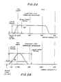
- Fig. 2A which relates to a retarder mechanism driven from the fuel injector cam
- the significant motion of the fuel injector pushtube for Cylinder No. 1 begins at about 30° BTDC as the piston in Cylinder No. 1 is completing its compression stroke. Since a lash of about 0.018" is normally provided in the valve train mechanism (by means of the adjusting screw 52) the initial motion of the slave piston 48, shown by curve 100, will take up the lash so that the exhaust valve begins to open at about 25° BTDC and reaches its maximum opening just after TDC. Thus, the work done in compressing air during the compression stroke is not recovered during the ensuing expansion stroke. It may be observed that both the timing of the travel and the extent of the travel of the slave piston 48 are such that a relatively large retarding horsepower can be developed by using an injector cam-driven mechanism.
- Fig. 2B shows a typical exhaust valve motion produced during engine retarding when the motion is derived from a remote exhaust pushtube and exhaust cam.
- the slave piston travel curve 102 begins sooner, ends later, travels farther and its rate of rise is lower than when the motion is derived from the injector cam, all of which are disadvantageous for purposes of driving the retarder.
- the exhaust valve travel must be limited to avoid interference between the exhaust valve and the engine piston at TDC. This may be accomplished by in creasing the valve train lash from the usual value of about 0.018" to, for example, 0.070", as shown in Fig. 2B.
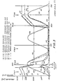
- Fig. 3 illustrates, graphically, the result of applicants' method and apparatus.
- the ordinate is pressure or motion plotted against the crankangle position, as abscissa, where TDC I represents the top dead center position of the piston in Cylinder No. 1 following the compression stroke and TDC II represents the top dead center position of the piston in Cylinder No. 1 following the exhaust stroke.
- Curve 104 represents the motion of the master piston driven by the intake pushtube for Cylinder No. 1; curve 105 represents the motion of the intake pushtube for Cylinder No. 1; curve 106 represents the motion of the exhaust pushtube for Cylinder No. 1; and curve 108 represents the motion of the exhaust pushtube for Cylinder No. 2.
- Curve 110 shows the variation in the pressure above the master piston driven by the intake pushtube for Cylinder No. 1; curve 112 shows the variation in the pressure above the master piston driven by the exhaust pushtube for Cylinder No. 2; curve 114 shows the variation in the cylinder pressure in Cylinder No. 1; and curve 116 shows the variation in the plenum pressure.
- Curve 118 shows the motion of the exhaust valve during engine retarding for Cylinder No. 1 resulting from the mechanism of the present invention while curve 120 shows the motion of the exhaust valve during engine retarding for Cylinder No. 1 without the mechanism of the present invention.
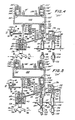
- FIG. 4 illustrates the condition of the mechanism when the compression retarding system has been shut off, e.g., the dash switch 90 (Fig. 1) or the three-position switch 84 (Fig. 1A) is in the "OFF" or open position.
- the mechanisms shown in Figs. 4-9 are related to the exhaust valve for Cylinder No. 1. It will be understood that a similar mechanism is provided for each cylinder of the engine. For a six cylinder engine having the normal firing order 1-5-3-6-2-4 the relationship between the cylinders may be shown in Table I below:
- the exhaust pushtube 122 for Cylinder No. 2 drives the exhaust rocker arm 124 for Cylinder No. 2 and, through the adjusting screw mechanism 126, the master piston 128 which reciprocates in the master cylinder 130 formed in the retarder housing 10.
- the master piston 128 is biased upwardly (as viewed in Figs. 4-9) by a light leaf spring 129.
- the intake pushtube 132 for Cylinder No. 1 drives the intake pushtube 132 for Cylinder No.
- the master piston 138 drives the intake rocker arm 134 for Cylinder No. 1 and, through the adjusting screw mechanism 136, the master piston 138 which reciprocates in the master cylinder 140 also formed in the retarder housing 10.
- the master piston 138 is biased in an upwardly direction (as viewed in Figs. 4-9) by a light leaf spring 139.
- a plenum chamber 142 is formed in the retarder housing 10.
- the plenum chamber 142 may have any desired shape provided that its volume is large enough to absorb, temporarily, at a reasonable pressure, energy delivered from the full travel of the intake master piston and a partial travel of the exhaust master piston sufficient to open the exhaust valve against the cylinder pressure within two engine cycles.
- the plenum size is determined by the bulk modulus of the working fluid, in this case, engine lubricating oil. For an engine having a displacement of about 2.35 liters per cylinder, applicants have found that a plenum volume of about 10 cubic inches is sufficient to service three cylinders.
- a standard six cylinder engine may conveniently be provided with two retarder housings 10, each housing having a 10 cubic inch plenum 142.
- the plenum 142 is provided with a driving cylinder 144 within which a free piston 146 may reciprocate against the bias of a compression spring 148.
- the cylinder 144 communicates with the plenum 142 through passageway 150.
- a passageway 152 communicates between the driving cylinder 144 and a trigger check valve 154 which controls flow through passageway 156 which, in turn, connects with passageway 44.
- Passageway 156 is aligned with, but is isolated from, the master cylinder 130.
- a pin 158 passing through a lap fit seal in the housing 10 contacts the end of master piston 128 and passes axially through the passageway156.
- Pin 158 is of sufficient length to displace the trigger check valve ball 160 against the bias of the spring 162 and the pressure in the passageway 152 when the master piston 128 approaches the upper limit of its travel within the master cylinder 130.
- a bypass 164 communicates between the master cylinder 130 and passageway 152.
- a passageway 166 communicates between the master cylinder 140 and a control check valve chamber 168 which, in turn, communicates with the bypass 164 through passageway 170.
- Control check valve cylinder 172 communicates with passageway 170 through passageway 174.
- Control check valve piston 176 reciprocates within the control check valve cylinder 172 and is biased toward the upward (as viewed in Figs. 4-9) or open position by a compression spring 178.
- the control check valve cylinder 172 is vented through duct 180.
- Control check valve 182 is located in the control check valve chamber 168 and connected to the control check valve piston 176 by a rod 184 passing through a lap fit seal in the housing 10.
- Slave cylinder 42 communicates with the plenum 142 through. a check valve 186 and a passageway 188. Check valve 186 permits flow only from the slave cylinder 42 toward the plenum 142.
- Fig. 4 represents the "Off position in which the solenoid valve 16 is closed and the oil in the system (other than the plenum) is vented to the engine sump.
- the control valve 24 is in the ''down'' (as viewed in Fig. 4) or closed position; trigger check valve 154 is held open by pin 158; control check valve 182 is open because the control check valve piston 176 is in its upward position (as seen in Fig. 4), the slave piston 48 rests against the stop 52 and the master pistons 128 and 138 are biased away from the adjusting screw mechanism 126 and 136.
- the retarding mechanism is out of contact with the operating parts of the engine so that the engine, in its operating mode, is entirely unaffected by the retarder mechanism.
- Fig. 5 shows the condition of the mechanis m when the retarder is turned to the "on" position.
- the solenoid valve 16 opens and low pressure oil flows from passageway 14 into passageway 20 and then into the control valve chamber 22 thereby raising the control valve 24 so that the circumferential groove 32 registers with passageway 40. Oil then flows past the ball check valve 34, through passageways 40 and 44 into the slave cylinder 42 and through a check valve 186 and passageway 188 into the plenum 142.
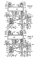
- Fig. 6 shows the conditions occurring at the peak of the upward motion of the intake pushtube 132 for Cylinder No. 1 (about 400°; see Fig. 3).
- the intake pushtube 132 moves upwardly (as viewed in Fig. 6) the master piston 138 is driven into the master cylinder 140 and oil is forced through passageway 166, past control check valve 182 and into the control check valve chamber 168.
- the control check valve 182 remains in the open position (as viewed in Fig. 5) until the pressure of the control check valve chamber 168 reaches about 1,000 psi. At this point, the control check valve 182 closes (as viewed in Fig. 6) and functions as a check valve.
- the pressure of the oil in the bypass 164 and the trigger check valve 154 assures that the trigger check valve ball 160 is seated and that the oil passes through passageway 152 and into the driving cylinder 144 so as to move the free piston 146 against the bias of spring 148 thereby rapidly increasing the pressure of the oil in the plenum 142.
- Fig. 7 shows the events which occur at about 680° crankangle position during a portion of the upward movement (as viewed in Fig. 7) of exhaust pushtube 122 for Cylinder No. 2.
- the exhaust pushtube 122 As the exhaust pushtube 122 is driven upwardly, it, in turn, drives the master piston 128 upwardly (as viewed in Fig. 7) and forces oil from the master cylinder 130 into the bypass 164, the passageway 152, the trigger check valve 154 and the driving cylinder 144.
- the resulting upward movement (as viewed in Fig. 7) of the free piston 146 causes the pressure to rise further in the plenum 142.
- the pin 158 contacts the trigger check valve ball 160 and forces it away from its seat. This event may occur, for example, at about 695° crankangle position.
- a volume of high pressure oil will be delivered rapidly through passageways 156, 44 (and also through passageway 40) to the slave cylinder 42 (see Fig. 8). If the amount of energy is sufficiently high to drive the slave piston 48 downwardly (as viewed in Fig. 8), the exhaust valve crosshead 70 will be actuated so as to open the exhaust valves near TDC I and thereby produce a compression release event.
- control check valve 182 remains closed and the master piston 138 remains in the upward position even though the pushtube 132 has retracted.
- the areas of control check valve 182 and piston 176 are coordinated with the spring rate of compression spring 178 so that whenever the pressure in passageways 170 and 174 rises above about 1,000 psi the control check valve 182 will close and will remain closed so as to function as a check valve until the pressure drops below about 400 psi.
- This design limits the oil introduced into the system to the amount required to attain a pressure sufficient to drive the slave piston 48 downwardly and therby open the exhaust valve, plus leakage.
- Oil which may leak past the slave piston 48 or the master pistons 128 and 138 is returned to the engine sump along with the oil used to lubricate the rocker arm assembly. Oil which may leak past the piston 176 and rod 184 is vented to the rocker arm region through vent duct 180. Oil released from the system over the control valve 24 when the system is turned off returns to the sump through duct means (not shown).
- a large plenum will require a number of engine cycles in order to attain its operating pressure level, but will maintain a more nearly constant pressure level during operation.
- a 10 cubic inch plenum adequate to service three cylinders of a 12 to 14 liter six cylinder engine. In this arrangement, operating plenum pressure can be attained within two engine cycles. It will be understood that applicants have utilized the compliance of the oil contained in the system, and, particularly in the plenum, to absorb and release the energy delivered by the master pistons.
- the compression release exhaust valve opening (curve 118) is triggered just before TDC I by the unseating of the trigger check valve ball 160 and is evidenced by a drop in plenum pressure (curve 116) or pressure above the exhaust master piston 128 (curve 112). Since the motion of the master piston 128 is precisely determined by the exhaust cam for Cylinder No. 2, the timing of the opening of the trigger check valve 154 is determined by the length of the pin 158. Thus, the timing of the compression release event is fully controllable by the designer. Moreover, the rate at which the exhaust valve opens depends on the amount of energy delivered from the driving cylinder 144 to the slave piston 48 and is independent of the shape of the injector, exhaust or intake cam which may thus be designed to best accommodate its primary function. However, because the exhaust valve may now be opened very rapidly and at any desired time, the retarding horsepower can be maximized for a given set of engine conditions.
- Fig. 10 illustrates, in schematic form, a modification of the trigger and control check valve mechanisms. To the extent that the parts in Fig. 10 are also shown in Figs. 4-9, the same designators will be used and the earlier description will not be repeated Modified parts will be designated by a subscript (a).
- the trigger check valve mechanism comprises a cavity 190 formed in the housing and communicating at one end with the master cylinder 130 and at the other end with passageway 152.
- the master cylinder 130 is formed with an annular cavity 192 which communicates with passageway 44 and permits a flow past the master piston 128 when that piston is in its uppermost position, as viewed in Fig. 10.
- a tubular valve element 194 having a rim 196 at its open end and a hole 198 at the opposite end is biased toward the bottom of the cavity 190 by a compression spring 200.
- the compression spring 200 is positioned between the top of the cavity 190 and the rim 196 of the tubular valve element 194.
- a piston 202 is adjustably mounted on one end of a connecting rod 204 for reciprocating movement within the tubular valve element 194.
- the opposite end of the connecting rod 204 is fixed to the master piston 128.
- the piston 202 and tubular valve element 194 function as a valve which opens whenever the master piston 128 moves far enough in an upward direction so that the piston 202 raises the tubular valve element 194 off its seat against the bias of compression spring 200 and the pressure within the cavity 190.
- motion of the master piston 128 and piston 202 pump hydraulic fluid from the cavity 190 through passageway 152 and into driving cylinder 144a.
- a firing cylinder 206 is formed within the plenum 142a coaxially with the driving cylinder 144a.
- the firing cylinder 206 is vented through passageway 208.
- a firing piston 210 is mounted for reciprocatory motion in the firing cylinder 206 and is spaced from the free piston 146 by a drive pin 212 which passes through a lap fit seal in the wall of the plenum 142a.
- a check valve chamber 214 is formed in the housing 10 and communicates with passageway 152 through passageway 216 and with the intake master cylinder 140 through passageway 218.
- Check valve 220 is biased toward a seat formed in the check valve chamber 214 mounted on a guide pin 226 which passes through a lap fit seal in the housing 10.
- One end of the guide pin 226 extends into passageway 228 which communicates with the plenum 142a. It will be noted that the pressure in the plenum 142a is applied to each side of the check valve 220, but the pressure is applied to different areas.
- the pressure exerted through passageway 216 is applied to the underlying area of the check valve 220 while the pressure exerted through passageway 228 is applied to the much smaller upper area of the guide pin 226, as viewed in Fig. 10. It will also be observed that when the free piston 146 is seated against the end of the driving cylinder 144a communicating with passageway 152, the pressure in passageways 152 and 216 may be substantially less than the pressure in the plenum 142a.
- the operation of the mechanism shown in Fig. 10 is substantially like that of the mechanism shown in Figs. 4-9.
- the check valve 220 When the retarder is in the "OFF" position, the check valve 220 will be held open so long as the pressure in the plenum 142a exceeds the pressure in passageway 152. Additionally, since the control valve 24 is in the "down" position (as shown in Fig. 9) the pressure in passageways 40, 44, 152 and 216 will be released and the master piston 128 will return to its uppermost position thereby holding tubular valve element 194 in the open position.
- hydraulic fluid When the retarder is turned on by energizing the solenoid valve 16, hydraulic fluid will be pumped at low pressure through passageways 40 and 44 and into master cylinder 130, cavity 190, passageways 152 and 216, check valve chamber 214, passageway 218 and master cylinder 140.
- master cylinder 130 When master cylinder 130 is filled, the tubular valve element 194 will seat.
- the intake valve pushtube for Cylinder No. 1 begins to drive master piston 138 upwardly (as shown in Fig. 10) so as to apply pressure to passageways 216 and 152, cavity 190 and free piston 146.
- master piston 138 stops its upward movement at about 450°, the check valve 220 will remain closed, thereby maintaining the pressure in cavity 190.
- the exhaust pushtube for Cylinder No. 2 begins to drive master piston 128 upwards (as shown in Fig. 10) thereby further pressurizing the cavity 190 and driving free piston 146 further in an upward direction. It will be understood that upward motion of the free piston 146 results in an increase in the pressure within the plenum 142a.
- piston 202 driven by the master piston 128 lifts the tubular valve element from its seat thereby permitting the pressure energy stored in the plenum 142a and the high pressure fluid under the free piston 146 to be delivered rapidly through passageway 44 to the slave cylinder 42.
- the slave piston 48 will drive the crosshead 70 downwardly against the valve stems 74 so as to open the exhaust valves 76.
- the hydraulic fluid will be pumped through check valve 186 into the plenum 142a. It will be appreciated that a small addition of hydraulic fluid to the plenum 142a will result in a substantial pressure rise in the plenum 142a during the ensuing cycle.
- Figs. 11A and 11B show additional details of the construction of the trigger check valve shown schematically in Fig. 10; Fig. llA shows the mechanism at the beginning of the stroke of the master piston 128 while Fig. 11B shows the mechanism at the end of the stroke of the master piston 128.
- Connecting rod 204 may be affixed to the master piston 128 by a pin 230 and is provided with a shoulder 232 adjacent the upper end of the master piston 128.
- the upper end of the connecting rod 204 is threaded to receive the adjustable piston 202.
- the piston 202 is locked into its adjusted position on the connecting rod 204 by a set screw 234.
- the piston 202 reciprocates within a tubular valve element 194 which is biased in a downwardly direction (as shown in Figs.
- a compression spring 200 mounted between the rim 196 of the tubular valve element 194 and a cap 236 which is threaded into the cavity 190.
- a valve seat 238 is also threaded into the cavity 190 adjacent to an enlarged portion 192 of the master cylinder 130.
- Passageway 44 communicates with the enlarged portion of the master cylinder 130 while passageway 152 communicates with the cavity 190 in the region between the bottom of the cap 236 and the top of the valve seat 238.
- compression spring 200 normally biases the tubular valve element 194 against the valve seat 238 so that piston 202 can pump hydraulic fluid through the hole 198, the cavity 190 and passageway 152.
- piston 202 lifts the tubular element 194 away from the valve seat 238, which occurs when the piston engages shoulder 198a on the tubular valve element 194, reverse flow of hydraulic fluid from passageway 152 through cavity 190 to passageway 44 occurs.
- Timing of the opening of the tubular valve element 194 may be controlled by adjusting the piston 202 relative to the connecting rod 204.
- Fig. 12 shows in more detail, the preferred check valve shown schematically in Fig. 10 which is associated with the intake master piston 138.
- Passageway 228 which leads to the plenum 142a contains an enlarged threaded bore 240 which communicates with passageway 218, master cylinder 140 and master piston 138.
- a further enlarged threaded bore 242 communicates axially with bore 240 and radially with passageway 216 which, through passageway 152 (Fig. 10), communicates with the driving cylinder 144a and the trigger check valve.
- a bushing 244 having an axial bore 246 is threaded into the bore 240.
- a lapped fit is provided between the guide pin 226 and the bore 246.
- a valve seat 248 having an axial bore 250 is threaded into the bore 240.
- a collar 252 is formed on the guide pin 226 to limit its axial travel in a direction toward the plenum 142a.
- a valve retaining cap 254 having an axial blind bore 246 and an axial boss 258 is threaded into the further enlarged bore 242.
- a relief passage 260 communicates between the bottom of the blind bore 246 and an inner surface of the valve retaining cap 254.
- a check valve 262 having a support pin 264 is mounted for reciprocating movement in the bore 246 of the retaining cap 254.
- a light compression spring 266 biases the valve 262 toward the valve seat 248 while plenum pressure in passageway 228 urges the guide pin 226 in a direction to move the check valve 262 away from the valve seat 248.
- Upward motion of the intake master piston 138 also tends to move the check valve 262 away from the valve seat 248.
- check valve 262 functions as an ordinary check valve.
- the check valve 262 will open whenever the pressure in passageway 216 and bore 242 falls below 500 psi. For this calculation, the force due to compression spring 266 has been neglected since it is relatively small. It will be understo od that when the check valve 262 is opened, hydraulic fluid may flow back into master cylinder 140 to prepare it for the next cycle of operation.
- a pushtube or rocker arm the motion of which occurs during the compression stroke of the cylinder to be retarded
- identifying a second pushtube or rocker arm the motion of which occurs during the exhaust stroke of the cylinder to be retarded (if two compression release events per engine cycle are desired)
- identifying a third pushtube or rocker arm the motion of which can be utilized to provide pumping (if a separate pumping action is desired).
- Properly sized master pistons may then be provided for each of the identified pushtubes and the system interconnected as shown, for example, in Figs. 4-9.
Landscapes
- Engineering & Computer Science (AREA)
- Mechanical Engineering (AREA)
- General Engineering & Computer Science (AREA)
- Chemical & Material Sciences (AREA)
- Combustion & Propulsion (AREA)
- Output Control And Ontrol Of Special Type Engine (AREA)
- Valve Device For Special Equipments (AREA)
- Braking Arrangements (AREA)
- Containers And Packaging Bodies Having A Special Means To Remove Contents (AREA)
- Valves And Accessory Devices For Braking Systems (AREA)
Abstract
Description
- The present invention relates to an engine retarding system and method of a gas compression release type. More particularly, the invention relates to a system and method for modifying the motion of the exhaust valve so as to open the valve more rapidly and at a predetermined time. The invention is particularly adapted for use in engines where the retarder is driven from an exhaust or intake cam.
- Engine retarders of the compression release type are well known in the art. In general, such retarders are designed temporarily to convert an internal combustion engine into an air compressor so as to develop a retarding horsepower which may be a substantial portion of the operating horsepower normally developed by the engine in its powering mode.
- The basic design of the compression release engine retarder is disclosed in the Cummins U.S. Patent 3,220,392. That design employs an hydraulic system wherein the motion of a master piston actuated by an intake, exhaust or injector pushrod or rocker arm controls the motion of a slave piston which, in turn opens the exhaust valve near its top dead center position whereby the work done during the compression stroke of the engine piston is not recovered during the expansion or power stroke but, instead, is dissipated through the engine exhaust and cooling systems.
- With compression ignition engines having a fuel injector driven from a third cam on the engine camshaft, it has been found to be desirable to derive the motion for the compression release retarder from the fuel injector pushtube for the cylinder experiencing the compression release event. The fuel injector pushtube is a desirable source of motion both because it peaks very shortly after the top dead center (TDC) position of the piston following the compression stroke and also because the effective stroke of the injector pushtube is completed in a relatively short period, e.g., 25-30 crankangle degrees. Further development of the injector-driven compression release retarder has disclosed the desirability of advancing the timing of the compression release event and this has been accomplished by a timing advance mechanism as disclosed in Custer U.S. Patent 4,398,510. The Custer mechanism automatically decreases the clearance or "lash" in the valve train mechanism so that the motion of the injector pushtube-driven master piston is delivered to the exhaust valve sooner. As the "lash" approaches zero, the motion of the exhaust valve approaches the motion defined by the injector cam. Although the total exhaust valve travel can be increased or decreased by varying the ratio of the diameter of the master and slave pistons (i.e., the "hydraulic ratio''), the elapsed time during which motion occurs is determined by the motion of the master piston which, in turn, is defined by the shape of the fuel injector cam.
- Many compression ignition engines employ fuel injection systems which are not driven from the engine camshaft and most spark ignition engines having fuel injection systems do not use an engine camshaft driven fuel injection system. Such engines, commonly known as two-cam engines to distinguish them from the three-cam engines referred to above utilize a remote intake or exhaust valve pushtube or cam to operate the compression release retarder. The valve motions produced by the intake and exhaust valve cams are similar to each other but significantly different from the motion produced by the injector cam. Typically, exhaust and intake valves require more than 90 crankangle degrees to move from the closed to the fully open position. Additionally, the exhaust cam generates a motion that begins too early, reaches its peak too late and provides a total travel which is too great for optimum retarding performance. Partial compensation for these disadvantages can be effected by increasing the slave piston lash and increasing the hydraulic ratio of the master and slave pistons. Also, as disclosed in Price et al U.S. Patent 4,485,780, the rate at which the exhaust valve is opened may be increased and the time of opening correspondingly decreased by employing a second master piston driven by an appropriate intake pushtube. Although the time of opening using the invention of the Price et al Patent 4,485,780 may be reduced from about 90 to about 50 crankangle degrees, the time is still above that available with an injector cam-driven retarder. As a result, and prior to the present invention, substantially less retarding horsepower can be developed from an exhaust cam-driven retarder than from an injector cam-driven retarder when both are optimized for the same engine.
- The problem therefore is to improve the performance of an exhaust cam-driven compression release retarder so that it will approach, or even exceed the performance of an injector cam-driven retarder.
- .Generally, we solve the noted problem by controlling the timing and the rate of opening of the exhaust valve to maximize the retarding horsepower. Because with the inventive system and method, the rate at which the exhaust valve is opened is independent of the shape of the ejector, exhaust or intake cam, the cam can be designed to best serve its primary function.
- More specifically and in accordance with the invention we provide an engine retarding system of a gas compression release type including an internal combustion engine having a hydraulic fluid supply, intake valve means, exhaust valve means, first and second pushtube means respectively acting on first and second master piston means displaceable in first and second master cylinder means, and hydraulically actuated slave piston means supplied with hydraulic fluid from said supply and operatively associated with said exhaust valve means to open said exhaust valve means, on supply of pressurized hydraulic fluid to said slave piston means, for a compression release event, characterized in that for controlling the timing and rate of opening of said exhaust valve means to maximize the retarding horsepower during a braking operational mode of the system, said system comprises plenum means including drive cylinder means in hydraulic fluid communication with said slave piston means which by means of first check valve means supplies hydraulic fluid uni-directionally from said slave piston means to said plenum means, said slave piston means being also in fluid communication with said first and second master cylinder means in which said first and second master piston means are displaceable by said first and second pushtubes, respectively, said first and second master piston means, when displaced in a pressure increasing direction in said first and second master cylinder means, being effective via said drive cylinder means to increase the pressure of the hydraulic fluid in said plenum means supplied thereto via said slave piston means on initiating said braking operational mode, second check valve means comprising a control check valve means operatively connected between said second master cylinder means and said plenum means and being in the path of hydraulic fluid therefrom and having an open position for hydraulic fluid pressure up to a predetermined value and a closed position for hydraulic fluid pressures above said predetermined value, and third check valve means comprising trigger check valve means aligned with said first master piston means and operatively connected between said slave piston means and said plenum means to permit a pulse of high pressure hydraulic fluid to be directed to said slave piston means from said plenum means for opening said exhaust valve means at a predetermined rate for a compression release event, said trigger check valve means having an open and a closed position, a bypass passage bypassing said trigger check valve means between said plenum means and said first master cylinder means said increased pressure hydraulic fluid in said plenum means, attributable to said first master piston means, passing through said bypass when said trigger check valve means is in its closed position, and trigger check valve opening means for moving said trigger check valve means to its open position at a predetermined time for triggering said pulse of high pressure hydraulic fluid from said drive cylinder means to said slave piston means.
- The trigger check valve means may be set to open at any desired point with respect to the top dead center position of the engine piston so as to deliver rapidly a predetermined volume of high pressure oil to the slave piston means, thus opening the exhaust valve means rapidly at a predetermined time. The hydraulic fluid supply automatically admits fresh oil as makeup for leakage and automatically limits the maximum pressure in the plenum to that pressure required to perform the compression release function. While the invention is particularly adapted for use in two-cam engines where the master pistons are driven from the exhaust and intake cams, it may also be applied to a three-cam engine where the master pistons can be driven from any of the injector, exhaust or intake cams. Accordingly, while the invention is particularly directed to the exhaust (or intake) cam-driven retarder, it may also be applied to an injector cam-driven retarder.
- Additional advantages of the novel combination according to the present invention will become apparent from the following description of the invention and the accompanying drawings in which:
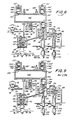
- Fig. 1 is a schematic diagram of a prior art compression release engine retarder of a type which may be modified to incorporate the principles and mechanisms of the present invention.
- Fig. 1A is a fragmentary schematic diagram showing an alternative electrical circuit for the apparatus as shown in Fig. 1.
- Fig. 2A is a diagram showing the typical motion of an exhaust valve during the retarding mode of operation in a retarder driven by an injector cam.
- Fig. 2B is a diagram showing the typical motion of an exhaust valve during the retarding mode of operation in a retarder driven by a remote exhaust or intake cam.
- Fig. 3 is a diagram showing the motion of certain master pistons, the exhaust valve and the pressures at certain points in the mechanism of the present invention as a function of the crankangle for a complete engine cycle.
- Fig. 4 is a schematic diagram of a compression release engine retarder in accordance with the present invention with the control switch in the "OFF" position.
- Fig. 5 is a schematic diagram of a compression release engine retarder in accordance with the present invention with the control switch in the "ON" position.
- Fig. 6 is a schematic diagram of a compression release engine retarder in accordance with the present invention showing the conditions prevailing during the upward travel of the intake master piston (about 460 crankangle degrees).
- Fig. 7 is a schematic diagram of a compression release engine retarder in accordance with the present invention showing the conditions prevailing during the upward travel of the exhaust master piston (about 680 crankangle degrees).
- Fig. 8 is a schematic diagram of a compression release engine retarder in accordance with the present invention showing the conditions prevailing during the initial part of the compression release event (about 14 crankangle degrees).
- Fig. 9 is a schematic diagram of a compression release engine retarder in accordance with the present invention showing the conditions prevailing at the end of the retarding cycle (about 140 crankangle degrees).
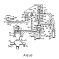
- Fig. 10 is a frag mentary diagram of a modified form of an engine retarder in accordance with the present invention incorporating a modified trigger check valve and a modified control check valve.
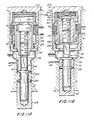
- Fig. 11A is a cross-sectional view of the modified trigger check valve shown in Fig. 10 in its unactuated position.
- Fig. 11B is a cross-sectional view of the trigger check valve of Fig. 11A in its actuated position.
- Fig. 12 is a cross-sectional view showing, in more detail, the modified control check valve indicated in Fig. 10.
- In order that the present invention may clearly be distinguished from the now well-known compression release engine retarder, reference will first be made to Fig. 1 which illustrates schematically a typical compression release engine retarder driven from the injector pushtube for the same cylinder or from the exhaust pushtube for another cylinder. The
retarder housing 10 is attached to theengine head 12 and carries the mechanism required to perform the retarding function. Typically, for exhaust cam driven retarders, onehousing 10 will contain the mechanism for three cylinders of a six-cylinder engine and asecond housing 10 will be used for the remaining three cylinders. Passageway 14 communicates between a two-position three-way solenoid valve 16 and the low pressure engine lubricating oil system (not shown). Drainpassageway 18 communicates between thesolenoid valve 16 and the engine sump (not shown) whilepassageway 20 communicates withcontrol valve chamber 22. In the energized or "on" position of thesolenoid valve 16, low pressure oil flows throughpassageways control valve chamber 22. In the deenergized or "off" position of thesolenoid 16,passageways position control valve 24 is mounted for reciprocatory motion in thecontrol valve chamber 22 and biased toward the bottom of thechamber 22 by acompression spring 26. Thecontrol valve 24 contains anaxial passageway 28 which intersects adiametral passageway 30. Acircumferential groove 32 communicates with thediametral passageway 30. Aball check valve 34 is biased against aseat 36 formed in theaxial passageway 28 by acompression spring 38. When thesolenoid valve 16 is energized, low pressure oil lifts thecontrol valve 24 against the bias ofspring 26 and then passes theball check valve 34. Apassageway 40 communicates between thecontrol valve chamber 22 and aslave cylinder 42 located in thehousing 10, while asecond passageway 44 communicates between theslave cylinder 42 and amaster cylinder 46, also located in thehousing 10. - A
slave piston 48 is mounted for reciprocatory motion within theslave cylinder 42. Theslave piston 48 is biased by acompression spring 50 toward an adjustingscrew 52 threaded into thehousing 10. The adjustingscrew 52 is locked in its adjusted position by alock nut 54. The lower end of thecompression spring 50 seats on aretainer plate 56 which is located in theslave cylinder 42 by asnap ring 58. - A
master piston 60 is mounted for reciprocatory motion in themaster cylinder 46 and is lightly biased in an upwardly direction (as shown in Fig. 1) by aleaf spring 62. Themaster piston 60 is located so as to register with the adjustingscrew mechanism 64 ofrocker arm 66. Therocker arm 66 is actuated by apushtube 68. If the retarder is driven from the fuel injector cam,rocker arm 66 will be the fuel injector rocker arm and thepushtube 68 will be the fuel injector pushtube for the cylinder associated withslave piston 48. However, if the retarder is driven, for example, from an exhaust valve cam, then therocker arm 66 andpushtube 68 will be the exhaust valve rocker arm and pushtube for a cylinder other than the one with which theslave piston 48 is associated. - The lower end of the
slave piston 48 is adapted to contact anexhaust valve crosshead 70. Thecrosshead 70 is mounted for reciprocatory motion on a pin 72 affixed to theengine head 12 and is adapted to contact the stems 74 of thedual exhaust valves 76 which are biased toward the closed position by valve springs 78. Theline 71 indicates the rest position of thecrosshead 70 when theexhaust valves 76 are closed. During the powering mode of engine operation, theexhaust valves 76 are opened by the actuation of the exhaustvalve rocker arm 80 which drives thecrosshead 70 downwardly (as viewed in Fig. 1) against the exhaust valve stems 74. - The electrical control circuit for the retarder comprises a
conduit 82 which runs from the coil of thesolenoid valve 16 to a three-position switch 84. Thereafter the circuit includes, in series, afuel pump switch 86, aclutch switch 88, a manual or dashswitch 90, afuse 92, thevehicle battery 94 and aground 96. Preferably, theswitches diode 98 which is grounded. It is convenient to use onesolenoid valve 16 to actuatecontrol valves 24 associated with one retarder housing. Thus theswitch 84 enables the operator to retard two, four or six cylinders of a six-cylinder engine in case of a three housing unit as contemplated by Fig. 1 or three or six cylinders of a six cylinder engine in case of a two housing unit as contemplated by Fig. 1A. As shown in Fig. 1A, no separatemanual switch 90 is required since the third position of the three position switch 84 functions as a manual "OFF" switch. Thefuel pump switch 86 and theclutch switch 88 are automatic switches which ensure that the fuel supply is interrupted during retarding and that the retarder is turned off whenever the clutch is disengaged. Thedash switch 90 enables the operator to deactivate the system. - In operation, energizing of the
solenoid 16 permits the flow of low pressure oil through thepassageways control valve chamber 22 and thence throughpassageways slave cylinder 42 andmaster cylinder 46. Reverse flow of oil from thepassageway 40 is prevented by theball check valve 34 located in thecontrol valve 24. Once the mechanism is filled with oil, upward motion (as viewed in Fig. 1) of themaster piston 60 as a result of the motion of thepushtube 68 will result in a corresponding downward motion (as viewed in Fig. 1) of theslave piston 48. This, in turn, causes theexhaust valves 76 to open. - Referring to Fig. 2A which relates to a retarder mechanism driven from the fuel injector cam, it will be noted that the significant motion of the fuel injector pushtube for Cylinder No. 1 begins at about 30° BTDC as the piston in Cylinder No. 1 is completing its compression stroke. Since a lash of about 0.018" is normally provided in the valve train mechanism (by means of the adjusting screw 52) the initial motion of the
slave piston 48, shown bycurve 100, will take up the lash so that the exhaust valve begins to open at about 25° BTDC and reaches its maximum opening just after TDC. Thus, the work done in compressing air during the compression stroke is not recovered during the ensuing expansion stroke. It may be observed that both the timing of the travel and the extent of the travel of theslave piston 48 are such that a relatively large retarding horsepower can be developed by using an injector cam-driven mechanism. - Fig. 2B shows a typical exhaust valve motion produced during engine retarding when the motion is derived from a remote exhaust pushtube and exhaust cam. It will be noted that the slave
piston travel curve 102, begins sooner, ends later, travels farther and its rate of rise is lower than when the motion is derived from the injector cam, all of which are disadvantageous for purposes of driving the retarder. Also, when utilizing a remote exhaust cam, the exhaust valve travel must be limited to avoid interference between the exhaust valve and the engine piston at TDC. This may be accomplished by in creasing the valve train lash from the usual value of about 0.018" to, for example, 0.070", as shown in Fig. 2B. An advantage of increasing the valve train lash is that the exhaust valve begins to open at a later time, e.g., about 55° BTDC, and thus the cylinder pressure can build to a higher level before the compression release event occurs. However, even when the exhaust cam operation is optimized it produces significantly less retarding horsepower than an injector cam-driven retarder. The ideal condition would be, of course, to let the cylinder pressure build to its maximum and then to open the exhaust valve instantaneously. Applicants provide a mechanism which approaches this ideal. - Reference is now made to Fig. 3 which illustrates, graphically, the result of applicants' method and apparatus. In Fig. 3 the ordinate is pressure or motion plotted against the crankangle position, as abscissa, where TDC I represents the top dead center position of the piston in Cylinder No. 1 following the compression stroke and TDC II represents the top dead center position of the piston in Cylinder No. 1 following the exhaust stroke.
Curve 104 represents the motion of the master piston driven by the intake pushtube for Cylinder No. 1;curve 105 represents the motion of the intake pushtube for Cylinder No. 1;curve 106 represents the motion of the exhaust pushtube for Cylinder No. 1; andcurve 108 represents the motion of the exhaust pushtube for Cylinder No. 2.Curve 110 shows the variation in the pressure above the master piston driven by the intake pushtube for Cylinder No. 1;curve 112 shows the variation in the pressure above the master piston driven by the exhaust pushtube for Cylinder No. 2;curve 114 shows the variation in the cylinder pressure in Cylinder No. 1; andcurve 116 shows the variation in the plenum pressure.Curve 118 shows the motion of the exhaust valve during engine retarding for Cylinder No. 1 resulting from the mechanism of the present invention while curve 120 shows the motion of the exhaust valve during engine retarding for Cylinder No. 1 without the mechanism of the present invention. - Reference is now made to Figs. 4-9 which show mechanism in accordance with the present invention in conjunction with the exhaust cam-driven retarder shown in Figs. 1 and 2B. Components which are common to all Figures carry the same designation. Fig. 4 illustrates the condition of the mechanism when the compression retarding system has been shut off, e.g., the dash switch 90 (Fig. 1) or the three-position switch 84 (Fig. 1A) is in the "OFF" or open position. The mechanisms shown in Figs. 4-9 are related to the exhaust valve for Cylinder No. 1. It will be understood that a similar mechanism is provided for each cylinder of the engine. For a six cylinder engine having the normal firing order 1-5-3-6-2-4 the relationship between the cylinders may be shown in Table I below:

- As the intake master pistons are used to pump up the pressure in the plenum, any of the three alternatives shown in Table I may be employed based on preference and ease of manufacture without significantly affecting the performance. For simplicity of description, Alternative C will be referred to hereafter. The exhaust pushtube 122 for Cylinder No. 2 drives the
exhaust rocker arm 124 for Cylinder No. 2 and, through the adjustingscrew mechanism 126, themaster piston 128 which reciprocates in themaster cylinder 130 formed in theretarder housing 10. Themaster piston 128 is biased upwardly (as viewed in Figs. 4-9) by alight leaf spring 129. Similarly, theintake pushtube 132 for Cylinder No. 1 drives theintake pushtube 132 for Cylinder No. 1 drives theintake rocker arm 134 for Cylinder No. 1 and, through the adjustingscrew mechanism 136, themaster piston 138 which reciprocates in themaster cylinder 140 also formed in theretarder housing 10. Themaster piston 138 is biased in an upwardly direction (as viewed in Figs. 4-9) by alight leaf spring 139. - A
plenum chamber 142 is formed in theretarder housing 10. Theplenum chamber 142 may have any desired shape provided that its volume is large enough to absorb, temporarily, at a reasonable pressure, energy delivered from the full travel of the intake master piston and a partial travel of the exhaust master piston sufficient to open the exhaust valve against the cylinder pressure within two engine cycles. The plenum size is determined by the bulk modulus of the working fluid, in this case, engine lubricating oil. For an engine having a displacement of about 2.35 liters per cylinder, applicants have found that a plenum volume of about 10 cubic inches is sufficient to service three cylinders. Thus, a standard six cylinder engine may conveniently be provided with tworetarder housings 10, each housing having a 10cubic inch plenum 142. - For each engine cylinder it services, the
plenum 142 is provided with adriving cylinder 144 within which afree piston 146 may reciprocate against the bias of acompression spring 148. Thecylinder 144 communicates with theplenum 142 throughpassageway 150. Apassageway 152 communicates between the drivingcylinder 144 and atrigger check valve 154 which controls flow throughpassageway 156 which, in turn, connects withpassageway 44.Passageway 156 is aligned with, but is isolated from, themaster cylinder 130. Apin 158 passing through a lap fit seal in thehousing 10 contacts the end ofmaster piston 128 and passes axially through the passageway156.Pin 158 is of sufficient length to displace the triggercheck valve ball 160 against the bias of thespring 162 and the pressure in thepassageway 152 when themaster piston 128 approaches the upper limit of its travel within themaster cylinder 130. A bypass 164 communicates between themaster cylinder 130 andpassageway 152. - A
passageway 166 communicates between themaster cylinder 140 and a controlcheck valve chamber 168 which, in turn, communicates with the bypass 164 throughpassageway 170. Controlcheck valve cylinder 172 communicates withpassageway 170 throughpassageway 174. Controlcheck valve piston 176 reciprocates within the controlcheck valve cylinder 172 and is biased toward the upward (as viewed in Figs. 4-9) or open position by a compression spring 178. The controlcheck valve cylinder 172 is vented throughduct 180.Control check valve 182 is located in the controlcheck valve chamber 168 and connected to the controlcheck valve piston 176 by a rod 184 passing through a lap fit seal in thehousing 10. -
Slave cylinder 42 communicates with theplenum 142 through. acheck valve 186 and apassageway 188.Check valve 186 permits flow only from theslave cylinder 42 toward theplenum 142. - It will be understood that mechanisms like those shown connected to
passageways passageways 188" and 152" for Cylinder No. 3. A duplicatesystem services Cylinders 4, 5 and 6. - The operation of the system will now be explained by a sequential reference to Figs. 4 through 9. As noted, Fig. 4 represents the "Off position in which the
solenoid valve 16 is closed and the oil in the system (other than the plenum) is vented to the engine sump. Thus, no oil pressure exists beyond thesolenoid valve 16; thecontrol valve 24 is in the ''down'' (as viewed in Fig. 4) or closed position; triggercheck valve 154 is held open bypin 158; controlcheck valve 182 is open because the controlcheck valve piston 176 is in its upward position (as seen in Fig. 4), theslave piston 48 rests against thestop 52 and themaster pistons screw mechanism - Fig. 5 shows the condition of the mechanis m when the retarder is turned to the "on" position. In this mode, the
solenoid valve 16 opens and low pressure oil flows frompassageway 14 intopassageway 20 and then into thecontrol valve chamber 22 thereby raising thecontrol valve 24 so that thecircumferential groove 32 registers withpassageway 40. Oil then flows past theball check valve 34, throughpassageways slave cylinder 42 and through acheck valve 186 andpassageway 188 into theplenum 142. Also, oil flows throughpassageways check valve ball 160 and into themaster cylinders passageway 170,check valve chamber 168 andpassageway 166, causing themaster pistons screw mechanisms slave piston 48 or thedriving piston 146. - Reference will now be made to Fig. 6 which shows the conditions occurring at the peak of the upward motion of the
intake pushtube 132 for Cylinder No. 1 (about 400°; see Fig. 3). As theintake pushtube 132 moves upwardly (as viewed in Fig. 6) themaster piston 138 is driven into themaster cylinder 140 and oil is forced throughpassageway 166, pastcontrol check valve 182 and into the controlcheck valve chamber 168. Thecontrol check valve 182 remains in the open position (as viewed in Fig. 5) until the pressure of the controlcheck valve chamber 168 reaches about 1,000 psi. At this point, thecontrol check valve 182 closes (as viewed in Fig. 6) and functions as a check valve. The pressure of the oil in the bypass 164 and thetrigger check valve 154 assures that the triggercheck valve ball 160 is seated and that the oil passes throughpassageway 152 and into the drivingcylinder 144 so as to move thefree piston 146 against the bias ofspring 148 thereby rapidly increasing the pressure of the oil in theplenum 142. - Reference is now made to Fig. 7 which shows the events which occur at about 680° crankangle position during a portion of the upward movement (as viewed in Fig. 7) of
exhaust pushtube 122 for Cylinder No. 2. As theexhaust pushtube 122 is driven upwardly, it, in turn, drives themaster piston 128 upwardly (as viewed in Fig. 7) and forces oil from themaster cylinder 130 into the bypass 164, thepassageway 152, thetrigger check valve 154 and thedriving cylinder 144. The resulting upward movement (as viewed in Fig. 7) of thefree piston 146 causes the pressure to rise further in theplenum 142. - At a predetermined point in the travel of
master piston 128, thepin 158 contacts the triggercheck valve ball 160 and forces it away from its seat. This event may occur, for example, at about 695° crankangle position. When the triggercheck valve ball 160 is unseated, a volume of high pressure oil will be delivered rapidly throughpassageways 156, 44 (and also through passageway 40) to the slave cylinder 42 (see Fig. 8). If the amount of energy is sufficiently high to drive theslave piston 48 downwardly (as viewed in Fig. 8), theexhaust valve crosshead 70 will be actuated so as to open the exhaust valves near TDC I and thereby produce a compression release event. If, on the other hand, the retarder has just been turned on and the pressure in theplenum chamber 142 is relatively low, the oil delivered to theslave cylinder 42 from the drivingcylinder 144 throughpassageway 152, on unseating the triggercheck valve ball 160, will pass throughcheck valve 186 andpassageway 188 and be delivered to theplenum chamber 142. The oil so delivered, together with any leakage, will be replaced through thecontrol valve 24 beginning during return motion of theexhaust pushtube 122 for Cylinder No. 2 and the corresponding downward motion ofmaster piston 128 and ending shortly before 360° crankangle position whenintake pushtube 132 for Cylinder No. 1 is again actuated. This latter condition is illustrated in Fig. 9 which shows theslave piston 42 in its rest position against thestop 52, triggercheck valve ball 160 seated, andmaster pistons - It will be noted in Figs. 7 and 8 that the
control check valve 182 remains closed and themaster piston 138 remains in the upward position even though thepushtube 132 has retracted. The areas ofcontrol check valve 182 andpiston 176 are coordinated with the spring rate of compression spring 178 so that whenever the pressure inpassageways control check valve 182 will close and will remain closed so as to function as a check valve until the pressure drops below about 400 psi. This design limits the oil introduced into the system to the amount required to attain a pressure sufficient to drive theslave piston 48 downwardly and therby open the exhaust valve, plus leakage. Oil which may leak past theslave piston 48 or themaster pistons piston 176 and rod 184 is vented to the rocker arm region throughvent duct 180. Oil released from the system over thecontrol valve 24 when the system is turned off returns to the sump through duct means (not shown). - It will be understood that the pressure rise in the
plenum 142 during each engine cycle depends upon the displacement of themaster pistons plenum 142. More particularly, the increase in plenum pressure may be determined by the formula:
Δp =β
Where Δp = Plenum pressure rise (psi)
ΔV = Volume of oil displace by master pistons (in.³)
V = System volume (plenum volume plus volume of related passages) (in.³)
β = Bulk Modulus of oil (approx. 200,000 psi for engine
oil.) Also, the pressure drop during a compression release event depends on the volume of the plenum. A large plenum will require a number of engine cycles in order to attain its operating pressure level, but will maintain a more nearly constant pressure level during operation. As noted above, applicants have found a 10 cubic inch plenum adequate to service three cylinders of a 12 to 14 liter six cylinder engine. In this arrangement, operating plenum pressure can be attained within two engine cycles. It will be understood that applicants have utilized the compliance of the oil contained in the system, and, particularly in the plenum, to absorb and release the energy delivered by the master pistons. - Referring to Fig. 3, the compression release exhaust valve opening (curve 118) is triggered just before TDC I by the unseating of the trigger
check valve ball 160 and is evidenced by a drop in plenum pressure (curve 116) or pressure above the exhaust master piston 128 (curve 112). Since the motion of themaster piston 128 is precisely determined by the exhaust cam for Cylinder No. 2, the timing of the opening of thetrigger check valve 154 is determined by the length of thepin 158. Thus, the timing of the compression release event is fully controllable by the designer. Moreover, the rate at which the exhaust valve opens depends on the amount of energy delivered from the drivingcylinder 144 to theslave piston 48 and is independent of the shape of the injector, exhaust or intake cam which may thus be designed to best accommodate its primary function. However, because the exhaust valve may now be opened very rapidly and at any desired time, the retarding horsepower can be maximized for a given set of engine conditions. - Tests on a six
cylinder 14 liter engine equipped with a conventional exhaust cam-driven retarder produced 275 horsepower at an engine speed of 2100 RPM. When this retarder was modified to test the concepts of the present invention, the retarding horsepower was increased by over 100 horsepower at the same engine speed. - Reference is now made to Fig. 10 which illustrates, in schematic form, a modification of the trigger and control check valve mechanisms. To the extent that the parts in Fig. 10 are also shown in Figs. 4-9, the same designators will be used and the earlier description will not be repeated Modified parts will be designated by a subscript (a).
- The trigger check valve mechanism comprises a
cavity 190 formed in the housing and communicating at one end with themaster cylinder 130 and at the other end withpassageway 152. Themaster cylinder 130 is formed with anannular cavity 192 which communicates withpassageway 44 and permits a flow past themaster piston 128 when that piston is in its uppermost position, as viewed in Fig. 10. Atubular valve element 194 having arim 196 at its open end and ahole 198 at the opposite end is biased toward the bottom of thecavity 190 by acompression spring 200. Thecompression spring 200 is positioned between the top of thecavity 190 and therim 196 of thetubular valve element 194. Apiston 202 is adjustably mounted on one end of a connectingrod 204 for reciprocating movement within thetubular valve element 194. The opposite end of the connectingrod 204 is fixed to themaster piston 128. It will be appreciated that thepiston 202 andtubular valve element 194 function as a valve which opens whenever themaster piston 128 moves far enough in an upward direction so that thepiston 202 raises thetubular valve element 194 off its seat against the bias ofcompression spring 200 and the pressure within thecavity 190. Until thetubular valve element 194 is lifted from its seat, motion of themaster piston 128 andpiston 202 pump hydraulic fluid from thecavity 190 throughpassageway 152 and into driving cylinder 144a. - A
firing cylinder 206 is formed within the plenum 142a coaxially with the driving cylinder 144a. Thefiring cylinder 206 is vented throughpassageway 208. Afiring piston 210 is mounted for reciprocatory motion in thefiring cylinder 206 and is spaced from thefree piston 146 by adrive pin 212 which passes through a lap fit seal in the wall of the plenum 142a. - A
check valve chamber 214 is formed in thehousing 10 and communicates withpassageway 152 throughpassageway 216 and with theintake master cylinder 140 throughpassageway 218.Check valve 220 is biased toward a seat formed in thecheck valve chamber 214 mounted on aguide pin 226 which passes through a lap fit seal in thehousing 10. One end of theguide pin 226 extends intopassageway 228 which communicates with the plenum 142a. It will be noted that the pressure in the plenum 142a is applied to each side of thecheck valve 220, but the pressure is applied to different areas. As will be apparent, the pressure exerted throughpassageway 216 is applied to the underlying area of thecheck valve 220 while the pressure exerted throughpassageway 228 is applied to the much smaller upper area of theguide pin 226, as viewed in Fig. 10. It will also be observed that when thefree piston 146 is seated against the end of the driving cylinder 144a communicating withpassageway 152, the pressure inpassageways - The operation of the mechanism shown in Fig. 10 is substantially like that of the mechanism shown in Figs. 4-9. When the retarder is in the "OFF" position, the
check valve 220 will be held open so long as the pressure in the plenum 142a exceeds the pressure inpassageway 152. Additionally, since thecontrol valve 24 is in the "down" position (as shown in Fig. 9) the pressure inpassageways master piston 128 will return to its uppermost position thereby holdingtubular valve element 194 in the open position. - When the retarder is turned on by energizing the
solenoid valve 16, hydraulic fluid will be pumped at low pressure throughpassageways master cylinder 130,cavity 190,passageways check valve chamber 214,passageway 218 andmaster cylinder 140. Whenmaster cylinder 130 is filled, thetubular valve element 194 will seat. - At about 360 crankangle degrees, the intake valve pushtube for Cylinder No. 1 begins to drive
master piston 138 upwardly (as shown in Fig. 10) so as to apply pressure topassageways cavity 190 andfree piston 146. When the pressure due to the motion ofmaster piston 138 exceeds the pressure in the plenum 142a, thefree piston 146 will be displaced upwardly. Whenmaster piston 138 stops its upward movement at about 450°, thecheck valve 220 will remain closed, thereby maintaining the pressure incavity 190. - At about 630 crankangle degrees, the exhaust pushtube for Cylinder No. 2 begins to drive
master piston 128 upwards (as shown in Fig. 10) thereby further pressurizing thecavity 190 and drivingfree piston 146 further in an upward direction. It will be understood that upward motion of thefree piston 146 results in an increase in the pressure within the plenum 142a. - At a predetermined point, which may be, for example, about 695 crankangle degrees,
piston 202 driven by themaster piston 128 lifts the tubular valve element from its seat thereby permitting the pressure energy stored in the plenum 142a and the high pressure fluid under thefree piston 146 to be delivered rapidly throughpassageway 44 to theslave cylinder 42. If the fluid pressure is high enough to overcome the engine cylinder pressure and the bias of the valve springs 74, theslave piston 48 will drive thecrosshead 70 downwardly against the valve stems 74 so as to open theexhaust valves 76. If the fluid pressure is insufficient to open the engine exhaust valve, the hydraulic fluid will be pumped throughcheck valve 186 into the plenum 142a. It will be appreciated that a small addition of hydraulic fluid to the plenum 142a will result in a substantial pressure rise in the plenum 142a during the ensuing cycle. - Consideration of the mechanism shown in Fig. 10 will reveal that although the lifting of the
tubular valve element 194 signals the beginning of the valve opening event, the rate at which the slave piston moves downwardly is controlled by the rate at which thefree piston 146 moves downwardly. The rate of motion offree piston 146 is proportional to the net downward force acting upon thepiston 146. Since the fluid pressure on each side of thefree piston 146 and the areas against which it acts are substantially equal, the net force available to drive thefree piston 146 downwardly is substantially equal to the spring rate ofcompression spring 148. Although it is desirable to maximize the rate ofspring 148, there are physical constraints in the apparatus which limit the spring rates which may be employed. In order to increase the net downward force available to accelerate thefree piston 146, applicants providefiring piston 210 and drivepin 212. It will be seen that the additional force acting downwardly on thefree piston 146 is proportional to the difference between the cross-sectional areas of thefiring piston 210 and thedrive pin 212. - Figs. 11A and 11B show additional details of the construction of the trigger check valve shown schematically in Fig. 10; Fig. llA shows the mechanism at the beginning of the stroke of the
master piston 128 while Fig. 11B shows the mechanism at the end of the stroke of themaster piston 128.Connecting rod 204 may be affixed to themaster piston 128 by apin 230 and is provided with ashoulder 232 adjacent the upper end of themaster piston 128. The upper end of the connectingrod 204 is threaded to receive theadjustable piston 202. Thepiston 202 is locked into its adjusted position on the connectingrod 204 by aset screw 234. Thepiston 202 reciprocates within atubular valve element 194 which is biased in a downwardly direction (as shown in Figs. 11A and 11B) by acompression spring 200 mounted between therim 196 of thetubular valve element 194 and acap 236 which is threaded into thecavity 190. Avalve seat 238 is also threaded into thecavity 190 adjacent to anenlarged portion 192 of themaster cylinder 130.Passageway 44 communicates with the enlarged portion of themaster cylinder 130 whilepassageway 152 communicates with thecavity 190 in the region between the bottom of thecap 236 and the top of thevalve seat 238. - It will be seen that
compression spring 200 normally biases thetubular valve element 194 against thevalve seat 238 so thatpiston 202 can pump hydraulic fluid through thehole 198, thecavity 190 andpassageway 152. When thepiston 202 lifts thetubular element 194 away from thevalve seat 238, which occurs when the piston engages shoulder 198a on thetubular valve element 194, reverse flow of hydraulic fluid frompassageway 152 throughcavity 190 topassageway 44 occurs. Timing of the opening of thetubular valve element 194 may be controlled by adjusting thepiston 202 relative to the connectingrod 204. - Fig. 12 shows in more detail, the preferred check valve shown schematically in Fig. 10 which is associated with the
intake master piston 138. -
Passageway 228 which leads to the plenum 142a contains an enlarged threadedbore 240 which communicates withpassageway 218,master cylinder 140 andmaster piston 138. A further enlarged threadedbore 242 communicates axially withbore 240 and radially withpassageway 216 which, through passageway 152 (Fig. 10), communicates with the driving cylinder 144a and the trigger check valve. Abushing 244 having anaxial bore 246 is threaded into thebore 240. A lapped fit is provided between theguide pin 226 and thebore 246. Avalve seat 248 having anaxial bore 250 is threaded into thebore 240. Preferably, acollar 252 is formed on theguide pin 226 to limit its axial travel in a direction toward the plenum 142a. Avalve retaining cap 254 having an axial blind bore 246 and anaxial boss 258 is threaded into the furtherenlarged bore 242. Arelief passage 260 communicates between the bottom of theblind bore 246 and an inner surface of thevalve retaining cap 254. - A
check valve 262 having asupport pin 264 is mounted for reciprocating movement in thebore 246 of the retainingcap 254. Alight compression spring 266 biases thevalve 262 toward thevalve seat 248 while plenum pressure inpassageway 228 urges theguide pin 226 in a direction to move thecheck valve 262 away from thevalve seat 248. Upward motion of theintake master piston 138 also tends to move thecheck valve 262 away from thevalve seat 248. - Whenever the
intake master piston 138 is driven upwardly (as shown in Fig. 12) and the pressure delivered by the master piston exceeds the plenum pressure, hydraulic fluid passes through thebore 250 ofvalve seat 248, displaces thecheck valve 262 and flows throughpassageway 216 towards the driving cylinder 144a (Fig. 10). Under these circumstances,check valve 262 functions as an ordinary check valve. - As
master piston 138 attains its full stroke and begins its return stroke, the pressure inbore 250 andpassageway 218 drops and thecheck valve 262 is held against itsseat 248 against the bias of the plenum pressure acting on the end ofguide pin 226. It will be noted that the area of thecheck valve 262 upon which the pressure from the driving cylinder 144a acts is larger than the cross-sectional area of theguide pin 226 which is exposed to the plenum pressure. Thus, the force tending to close thecheck valve 262 will be larger than the force from theguide pin 226 tending to open the check valve. If, for example, the ratio of the cross-sectional areas of thecheck valve 262 andguide pin 226 is 7 and the plenum pressure is 3,500 psi, thecheck valve 262 will open whenever the pressure inpassageway 216 and bore 242 falls below 500 psi. For this calculation, the force due tocompression spring 266 has been neglected since it is relatively small. It will be understo od that when thecheck valve 262 is opened, hydraulic fluid may flow back intomaster cylinder 140 to prepare it for the next cycle of operation. - While the description has proceeded to the present principally with respect to the improvement of an exhaust pushtube-actuated retarder, it will be appreciated that the principles herein outlined are equally applicable to an injector pushtube-actuated retarder. However, when applied to an injector pushtube-driven retarder the improvement in performance will be less dramatic because the characteristics of the injector cam are more favorable for retarding purposes than those of the exhaust cam.
- In U.S. Patents 4,572,114 and 4,592,319, retarding processes and apparatus are disclosed for producing two compression release events per cylinder per engine cycle, i.e., one compression release event per cylinder per crankshaft revolution. The invention disclosed herein may also be used in conjunction with the inventions, disclosed in the above-cited patent and patent application. Considering a six cylinder engine having the usual firing order 1-5-3-6-2-4, a retarding system providing two compression release events per engine cycle may be arranged as set forth in Table II below:

- For engines having no fuel injector cam or pushtube an arrangement as set forth below in Tables III or IV is feasible:

- It will be noted that in Tables III and IV no master cylinder and piston is provided to perform the pumping function of
master cylinder 140 andmaster piston 138 in Figs. 4-9. In order to meet the pumping requirements of the master cylinders and pistons associated with the exhaust and/or intake pushtubes may be increased in diameter. This, of course, will cause an increase in the pushtube loading and care must be taken not to exceed the design load limits for these components. - For purposes of clarity and simplicity, the above description has been based on a six cylinder engine having a firing order 1-5-3-6-2-4. Other firing orders may be encountered as well as engines having differing numbers of cylinders. The present invention may be applied to such engines by identifying a pushtube or rocker arm the motion of which occurs during the compression stroke of the cylinder to be retarded; identifying a second pushtube or rocker arm the motion of which occurs during the exhaust stroke of the cylinder to be retarded (if two compression release events per engine cycle are desired); and/or identifying a third pushtube or rocker arm the motion of which can be utilized to provide pumping (if a separate pumping action is desired). Properly sized master pistons may then be provided for each of the identified pushtubes and the system interconnected as shown, for example, in Figs. 4-9.
- The terms and expressions which have been employed are used as terms of description and not of limitation and there is no intention in the use of such terms and expressions of excluding any equivalents of the features shown and described or portions thereof but it is recognized that various modifications are possible within the scope of the invention claimed.
Claims (20)
Priority Applications (1)
| Application Number | Priority Date | Filing Date | Title |
|---|---|---|---|
| AT87108187T ATE57739T1 (en) | 1986-06-10 | 1987-06-05 | ENGINE BRAKING DEVICE AND METHOD OF ENGINE BRAKING BY RELEASING COMPRESSION. |
Applications Claiming Priority (2)
| Application Number | Priority Date | Filing Date | Title |
|---|---|---|---|
| US06/872,494 US4706624A (en) | 1986-06-10 | 1986-06-10 | Compression release retarder with valve motion modifier |
| US872494 | 1986-06-10 |
Publications (3)
| Publication Number | Publication Date |
|---|---|
| EP0249833A2 true EP0249833A2 (en) | 1987-12-23 |
| EP0249833A3 EP0249833A3 (en) | 1988-05-18 |
| EP0249833B1 EP0249833B1 (en) | 1990-10-24 |
Family
ID=25359677
Family Applications (1)
| Application Number | Title | Priority Date | Filing Date |
|---|---|---|---|
| EP87108187A Expired - Lifetime EP0249833B1 (en) | 1986-06-10 | 1987-06-05 | An engine retarding system and method of a gas compression release type |
Country Status (10)
| Country | Link |
|---|---|
| US (1) | US4706624A (en) |
| EP (1) | EP0249833B1 (en) |
| KR (1) | KR920009140B1 (en) |
| CN (1) | CN1004569B (en) |
| AT (1) | ATE57739T1 (en) |
| AU (3) | AU590084B2 (en) |
| CA (1) | CA1328384C (en) |
| DE (1) | DE3765700D1 (en) |
| MX (1) | MX165966B (en) |
| NZ (1) | NZ220575A (en) |
Cited By (1)
| Publication number | Priority date | Publication date | Assignee | Title |
|---|---|---|---|---|
| EP0432404A3 (en) * | 1989-12-02 | 1991-10-02 | Man Nutzfahrzeuge Aktiengesellschaft | Valve control for distribution valves of internal combustion engines |
Families Citing this family (26)
| Publication number | Priority date | Publication date | Assignee | Title |
|---|---|---|---|---|
| US4793307A (en) * | 1987-06-11 | 1988-12-27 | The Jacobs Manufacturing Company | Rocker arm decoupler for two-cycle engine retarder |
| US4932372A (en) * | 1988-05-02 | 1990-06-12 | Pacific Diesel Brake Co. | Apparatus and method for retarding a turbocharged engine |
| US5000145A (en) * | 1989-12-05 | 1991-03-19 | Quenneville Raymond N | Compression release retarding system |
| US5036810A (en) * | 1990-08-07 | 1991-08-06 | Jenara Enterprises Ltd. | Engine brake and method |
| US5012778A (en) * | 1990-09-21 | 1991-05-07 | Jacobs Brake Technology Corporation | Externally driven compression release retarder |
| US5315974A (en) * | 1990-11-23 | 1994-05-31 | Ab Volvo | Internal combustion engine with compressor function |
| US5105782A (en) * | 1991-02-27 | 1992-04-21 | Jenara Enterprises Ltd. | Compression release brake with variable ratio master and slave cylinder combination |
| US5386809A (en) * | 1993-10-26 | 1995-02-07 | Cummins Engine Company, Inc. | Pressure relief valve for compression engine braking system |
| US5540201A (en) * | 1994-07-29 | 1996-07-30 | Caterpillar Inc. | Engine compression braking apparatus and method |
| US5647318A (en) * | 1994-07-29 | 1997-07-15 | Caterpillar Inc. | Engine compression braking apparatus and method |
| US5526784A (en) * | 1994-08-04 | 1996-06-18 | Caterpillar Inc. | Simultaneous exhaust valve opening braking system |
| JP2689314B2 (en) * | 1995-02-03 | 1997-12-10 | 三菱自動車工業株式会社 | Engine braking device for internal combustion engine |
| US5495838A (en) * | 1995-05-12 | 1996-03-05 | Caterpillar Inc. | Compression braking system |
| US5507261A (en) * | 1995-05-12 | 1996-04-16 | Caterpillar Inc. | Four cycle engine with two cycle compression braking system |
| US5809964A (en) | 1997-02-03 | 1998-09-22 | Diesel Engine Retarders, Inc. | Method and apparatus to accomplish exhaust air recirculation during engine braking and/or exhaust gas recirculation during positive power operation of an internal combustion engine |
| US6205975B1 (en) | 1999-12-16 | 2001-03-27 | Caterpillar Inc. | Method and apparatus for controlling the actuation of a compression brake |
| US6470851B1 (en) | 2000-10-30 | 2002-10-29 | Caterpillar Inc | Method and apparatus of controlling the actuation of a compression brake |
| US6405707B1 (en) | 2000-12-18 | 2002-06-18 | Caterpillar Inc. | Integral engine and engine compression braking HEUI injector |
| CN101270693A (en) * | 2002-04-08 | 2008-09-24 | 柴油发动机减震器有限公司 | Compact lost motion system for variable valve actuation |
| US20040083994A1 (en) * | 2002-10-30 | 2004-05-06 | Homa Afjeh | System for actuating an engine valve |
| CN102477906A (en) * | 2010-11-23 | 2012-05-30 | 广西玉柴机器股份有限公司 | Air starting engine |
| KR20180008556A (en) | 2015-05-18 | 2018-01-24 | 이턴 에스알엘 | A rocker arm with an oil drain valve acting as an accumulator |
| CN106762131B (en) * | 2017-03-14 | 2022-10-14 | 观致汽车有限公司 | Engine system and automobile applying same |
| CN110998072B (en) * | 2017-08-03 | 2021-11-09 | 雅各布斯车辆系统公司 | System and method for reverse flow management and valve motion sequencing in an enhanced internal combustion engine |
| CN110017393B (en) * | 2018-01-08 | 2024-04-12 | 上海气立可气动设备有限公司 | Electric control boosting type slow-start valve |
| CN109720314B (en) * | 2018-12-30 | 2020-07-28 | 潍柴动力股份有限公司 | Braking method, device and system |
Family Cites Families (13)
| Publication number | Priority date | Publication date | Assignee | Title |
|---|---|---|---|---|
| US3317181A (en) * | 1965-08-24 | 1967-05-02 | Jr Roland W Robbins | Fully sealed, pressure operated metering valve |
| BE697578A (en) * | 1966-05-14 | 1967-10-02 | ||
| US3405699A (en) * | 1966-06-17 | 1968-10-15 | Jacobs Mfg Co | Engine braking system with trip valve controlled piston |
| DE2423643A1 (en) * | 1973-05-19 | 1974-12-05 | Girling Ltd | CLOSED FLOW CONTROL VALVE FOR PRESSURE MEDIUM |
| DE2805040C3 (en) * | 1978-02-07 | 1982-02-25 | Heilmeier & Weinlein Fabrik für Oel-Hydraulik GmbH & Co KG, 8000 München | Releasable check valve screwed into a threaded hole |
| US4398510A (en) * | 1978-11-06 | 1983-08-16 | The Jacobs Manufacturing Company | Timing mechanism for engine brake |
| US4384558A (en) * | 1981-08-03 | 1983-05-24 | Cummins Engine Company, Inc. | Engine compression brake employing automatic lash adjustment |
| US4399787A (en) * | 1981-12-24 | 1983-08-23 | The Jacobs Manufacturing Company | Engine retarder hydraulic reset mechanism |
| US4423712A (en) * | 1982-04-28 | 1984-01-03 | The Jacobs Mfg. Company | Engine retarder slave piston return mechanism |
| US4510900A (en) * | 1982-12-09 | 1985-04-16 | The Jacobs Manufacturing Company | Hydraulic pulse engine retarder |
| US4485780A (en) * | 1983-05-05 | 1984-12-04 | The Jacobs Mfg. Company | Compression release engine retarder |
| US4572114A (en) * | 1984-06-01 | 1986-02-25 | The Jacobs Manufacturing Company | Process and apparatus for compression release engine retarding producing two compression release events per cylinder per engine cycle |
| US4592319A (en) * | 1985-08-09 | 1986-06-03 | The Jacobs Manufacturing Company | Engine retarding method and apparatus |
-
1986
- 1986-06-10 US US06/872,494 patent/US4706624A/en not_active Ceased
-
1987
- 1987-05-26 AU AU73428/87A patent/AU590084B2/en not_active Ceased
- 1987-06-05 CA CA000538943A patent/CA1328384C/en not_active Expired - Fee Related
- 1987-06-05 AT AT87108187T patent/ATE57739T1/en not_active IP Right Cessation
- 1987-06-05 NZ NZ220575A patent/NZ220575A/en unknown
- 1987-06-05 DE DE8787108187T patent/DE3765700D1/en not_active Expired - Lifetime
- 1987-06-05 EP EP87108187A patent/EP0249833B1/en not_active Expired - Lifetime
- 1987-06-09 MX MX006837A patent/MX165966B/en unknown
- 1987-06-10 CN CN87104111.1A patent/CN1004569B/en not_active Expired
- 1987-06-10 KR KR1019870005892A patent/KR920009140B1/en not_active Expired
-
1988
- 1988-09-13 AU AU22149/88A patent/AU610931B2/en not_active Ceased
-
1991
- 1991-03-11 AU AU72764/91A patent/AU633706B2/en not_active Ceased
Cited By (1)
| Publication number | Priority date | Publication date | Assignee | Title |
|---|---|---|---|---|
| EP0432404A3 (en) * | 1989-12-02 | 1991-10-02 | Man Nutzfahrzeuge Aktiengesellschaft | Valve control for distribution valves of internal combustion engines |
Also Published As
| Publication number | Publication date |
|---|---|
| AU7276491A (en) | 1991-05-30 |
| ATE57739T1 (en) | 1990-11-15 |
| AU590084B2 (en) | 1989-10-26 |
| DE3765700D1 (en) | 1990-11-29 |
| US4706624A (en) | 1987-11-17 |
| CN1004569B (en) | 1989-06-21 |
| AU7342887A (en) | 1987-12-17 |
| KR920009140B1 (en) | 1992-10-13 |
| AU633706B2 (en) | 1993-02-04 |
| AU2214988A (en) | 1988-12-15 |
| MX165966B (en) | 1992-12-14 |
| EP0249833A3 (en) | 1988-05-18 |
| AU610931B2 (en) | 1991-05-30 |
| CN87104111A (en) | 1988-05-18 |
| EP0249833B1 (en) | 1990-10-24 |
| CA1328384C (en) | 1994-04-12 |
| NZ220575A (en) | 1988-10-28 |
| KR880000679A (en) | 1988-03-28 |
Similar Documents
| Publication | Publication Date | Title |
|---|---|---|
| EP0249833B1 (en) | An engine retarding system and method of a gas compression release type | |
| CA1271675A (en) | Engine retarding method and apparatus | |
| EP0167267B1 (en) | Process and system for compression release engine retarding | |
| US4473047A (en) | Compression release engine brake | |
| EP0828061B1 (en) | Exhaust pulse boosted engine compression braking method | |
| EP0083058B1 (en) | Retarding system of a gas compression relief type | |
| US5000145A (en) | Compression release retarding system | |
| US4793307A (en) | Rocker arm decoupler for two-cycle engine retarder | |
| WO1999025969A1 (en) | Two cycle engine having a mono-valve integrated with a fuel injector | |
| US4898206A (en) | Compression release retarder with valve motion modifier | |
| USRE33052E (en) | Compression release retarder with valve motion modifier | |
| US4996957A (en) | Control valve for a compression release engine retarder | |
| US4949751A (en) | Compression release retarder with valve motion modifier | |
| US4838516A (en) | Compression release retarder with valve motion modifier | |
| US6321717B1 (en) | Double-lift exhaust pulse boosted engine compression braking method | |
| KR890003588B1 (en) | Decompression delay method and apparatus of engine | |
| NZ217093A (en) | Compression release 1.c.engine retarding process using electronic control of hydraulic circuits for valve actuation |
Legal Events
| Date | Code | Title | Description |
|---|---|---|---|
| PUAI | Public reference made under article 153(3) epc to a published international application that has entered the european phase |
Free format text: ORIGINAL CODE: 0009012 |
|
| AK | Designated contracting states |
Kind code of ref document: A2 Designated state(s): AT BE CH DE FR GB IT LI LU NL SE |
|
| PUAL | Search report despatched |
Free format text: ORIGINAL CODE: 0009013 |
|
| AK | Designated contracting states |
Kind code of ref document: A3 Designated state(s): AT BE CH DE FR GB IT LI LU NL SE |
|
| 17P | Request for examination filed |
Effective date: 19880721 |
|
| 17Q | First examination report despatched |
Effective date: 19890510 |
|
| ITF | It: translation for a ep patent filed | ||
| GRAA | (expected) grant |
Free format text: ORIGINAL CODE: 0009210 |
|
| AK | Designated contracting states |
Kind code of ref document: B1 Designated state(s): AT BE CH DE FR GB IT LI LU NL SE |
|
| REF | Corresponds to: |
Ref document number: 57739 Country of ref document: AT Date of ref document: 19901115 Kind code of ref document: T |
|
| REF | Corresponds to: |
Ref document number: 3765700 Country of ref document: DE Date of ref document: 19901129 |
|
| ET | Fr: translation filed | ||
| PG25 | Lapsed in a contracting state [announced via postgrant information from national office to epo] |
Ref country code: AT Effective date: 19910605 |
|
| PG25 | Lapsed in a contracting state [announced via postgrant information from national office to epo] |
Ref country code: LU Free format text: LAPSE BECAUSE OF NON-PAYMENT OF DUE FEES Effective date: 19910630 Ref country code: LI Effective date: 19910630 Ref country code: CH Effective date: 19910630 Ref country code: BE Effective date: 19910630 |
|
| PLBE | No opposition filed within time limit |
Free format text: ORIGINAL CODE: 0009261 |
|
| STAA | Information on the status of an ep patent application or granted ep patent |
Free format text: STATUS: NO OPPOSITION FILED WITHIN TIME LIMIT |
|
| 26N | No opposition filed | ||
| BERE | Be: lapsed |
Owner name: THE JACOBS MFG CY Effective date: 19910630 |
|
| PG25 | Lapsed in a contracting state [announced via postgrant information from national office to epo] |
Ref country code: NL Effective date: 19920101 |
|
| NLV4 | Nl: lapsed or anulled due to non-payment of the annual fee | ||
| REG | Reference to a national code |
Ref country code: CH Ref legal event code: PL |
|
| ITTA | It: last paid annual fee | ||
| EAL | Se: european patent in force in sweden |
Ref document number: 87108187.3 |
|
| PGFP | Annual fee paid to national office [announced via postgrant information from national office to epo] |
Ref country code: FR Payment date: 20000601 Year of fee payment: 14 |
|
| PGFP | Annual fee paid to national office [announced via postgrant information from national office to epo] |
Ref country code: GB Payment date: 20000602 Year of fee payment: 14 Ref country code: DE Payment date: 20000602 Year of fee payment: 14 |
|
| PGFP | Annual fee paid to national office [announced via postgrant information from national office to epo] |
Ref country code: SE Payment date: 20000605 Year of fee payment: 14 |
|
| PG25 | Lapsed in a contracting state [announced via postgrant information from national office to epo] |
Ref country code: GB Free format text: LAPSE BECAUSE OF NON-PAYMENT OF DUE FEES Effective date: 20010605 |
|
| PG25 | Lapsed in a contracting state [announced via postgrant information from national office to epo] |
Ref country code: SE Free format text: LAPSE BECAUSE OF NON-PAYMENT OF DUE FEES Effective date: 20010606 |
|
| GBPC | Gb: european patent ceased through non-payment of renewal fee |
Effective date: 20010605 |
|
| EUG | Se: european patent has lapsed |
Ref document number: 87108187.3 |
|
| PG25 | Lapsed in a contracting state [announced via postgrant information from national office to epo] |
Ref country code: FR Free format text: LAPSE BECAUSE OF NON-PAYMENT OF DUE FEES Effective date: 20020228 |
|
| PG25 | Lapsed in a contracting state [announced via postgrant information from national office to epo] |
Ref country code: DE Free format text: LAPSE BECAUSE OF NON-PAYMENT OF DUE FEES Effective date: 20020403 |
|
| PG25 | Lapsed in a contracting state [announced via postgrant information from national office to epo] |
Ref country code: IT Free format text: LAPSE BECAUSE OF NON-PAYMENT OF DUE FEES;WARNING: LAPSES OF ITALIAN PATENTS WITH EFFECTIVE DATE BEFORE 2007 MAY HAVE OCCURRED AT ANY TIME BEFORE 2007. THE CORRECT EFFECTIVE DATE MAY BE DIFFERENT FROM THE ONE RECORDED. Effective date: 20050605 |