EP0248948B1 - Tube fitting - Google Patents
Tube fitting Download PDFInfo
- Publication number
- EP0248948B1 EP0248948B1 EP86117463A EP86117463A EP0248948B1 EP 0248948 B1 EP0248948 B1 EP 0248948B1 EP 86117463 A EP86117463 A EP 86117463A EP 86117463 A EP86117463 A EP 86117463A EP 0248948 B1 EP0248948 B1 EP 0248948B1
- Authority
- EP
- European Patent Office
- Prior art keywords
- sleeve
- tube
- tubular member
- fitting
- further characterized
- Prior art date
- Legal status (The legal status is an assumption and is not a legal conclusion. Google has not performed a legal analysis and makes no representation as to the accuracy of the status listed.)
- Expired
Links
- 239000000314 lubricant Substances 0.000 claims description 13
- RTAQQCXQSZGOHL-UHFFFAOYSA-N Titanium Chemical compound [Ti] RTAQQCXQSZGOHL-UHFFFAOYSA-N 0.000 claims description 5
- 239000010936 titanium Substances 0.000 claims description 5
- 229910052719 titanium Inorganic materials 0.000 claims description 5
- CWQXQMHSOZUFJS-UHFFFAOYSA-N molybdenum disulfide Chemical compound S=[Mo]=S CWQXQMHSOZUFJS-UHFFFAOYSA-N 0.000 claims description 2
- 230000007423 decrease Effects 0.000 claims 1
- 239000012777 electrically insulating material Substances 0.000 claims 1
- 239000010410 layer Substances 0.000 description 5
- 239000002828 fuel tank Substances 0.000 description 4
- 230000002500 effect on skin Effects 0.000 description 3
- 238000010276 construction Methods 0.000 description 2
- 238000005336 cracking Methods 0.000 description 2
- 230000000694 effects Effects 0.000 description 1
- 239000000463 material Substances 0.000 description 1
- 230000013011 mating Effects 0.000 description 1
- 229910052751 metal Inorganic materials 0.000 description 1
- 239000002184 metal Substances 0.000 description 1
- 238000012986 modification Methods 0.000 description 1
- 230000004048 modification Effects 0.000 description 1
- 239000002344 surface layer Substances 0.000 description 1
Images
Classifications
-
- F—MECHANICAL ENGINEERING; LIGHTING; HEATING; WEAPONS; BLASTING
- F16—ENGINEERING ELEMENTS AND UNITS; GENERAL MEASURES FOR PRODUCING AND MAINTAINING EFFECTIVE FUNCTIONING OF MACHINES OR INSTALLATIONS; THERMAL INSULATION IN GENERAL
- F16L—PIPES; JOINTS OR FITTINGS FOR PIPES; SUPPORTS FOR PIPES, CABLES OR PROTECTIVE TUBING; MEANS FOR THERMAL INSULATION IN GENERAL
- F16L13/00—Non-disconnectable pipe joints, e.g. soldered, adhesive, or caulked joints
- F16L13/14—Non-disconnectable pipe joints, e.g. soldered, adhesive, or caulked joints made by plastically deforming the material of the pipe, e.g. by flanging, rolling
- F16L13/146—Non-disconnectable pipe joints, e.g. soldered, adhesive, or caulked joints made by plastically deforming the material of the pipe, e.g. by flanging, rolling by an axially moveable sleeve
Definitions
- the fitting of the invention is particularly suited for use in the hydraulic system of an aircraft.
- the fittings described above are preferably formed of a metal such as titanium which is lightweight, and yet exhibits high fatigue strength.
- titanium is subject to galling, and it has been found necessary to place dry lubricant between various components of the fitting, and between the fitting and the tube, so that any motion between the tube and the fitting, and between the components of the fitting will not produce fretting fatigue cracks.
- the present invention comprises a fitting for an electrically conductive tube comprising: an electrically conductive sleeve extending over the end of the tube in coaxial relationship therewith; an annular electrically conductive tubular member positioned over said sleeve in coaxial relationship therewith for compressing the sleeve against the end of the tube to provide a high strength fluid-tight joint between the sleeve and the tube; layers of dry lubricant interposed between the inner surface of the tubular member and the outer surface of the sleeve and between the sleeve and the tube; a portion of the inner surface of said tubular member at each end thereof is in intimate engagement with the outer surface of said sleeve and in electrical contact therewith and a portion of the inner surface of said sleeve is in intimate engagement with the outer surface of said tube and in electrical contact therewith.
- the present invention provides a fitting of the type described above which is constructed to provide a conductive path for high currents due to lightning strikes, and the like, from the surface of the tube and through the fitting, in a manner to preclude any tendency for arcing to occur across the components separated by the dry lubricant.
- the fitting of the invention is used to join two tubes 10 and 12 which are axially aligned with respect to one another.
- the fitting includes a sleeve having a first section 14a and a second section 14b which are mirror images of one another.
- the section 14a of the fitting includes an intermediate angled portion 14 ⁇ a having an increased outer diameter with respect to the remaining portion of the sleeve, and having finite length.
- Sleeve section 14b includes a similar angled portion 14 ⁇ b which is displaced axially from portion 14 ⁇ a.
- the angled portions 14 ⁇ a and 14 ⁇ b form shoulders which permit a first annular tubular member 16a to be forced over sleeve 14a, and which permit a second annular tubular member 16b to be forced over sleeve 14b by appropriate tools.
- the fitting itself may be generally similar to the fittings described, for example, in U.S. Patents 4,026,006; 3,893,720; 4,482,174 and 4,061,367.
- the components of the fittings when such fittings are used in aircraft, it is usual for the components of the fittings to be formed of titanium, and to be used for providing joints in the titanium tubes of the hydraulic system of the aircraft.
- a dry lubricant formed, for example, of molybdenum disulphide, between the components of the fitting and between the fitting and the tube so as to avoid fretting fatigue cracking due to relative movement between the components and between the fitting and the tube due to galling.
- annular tubular member 16a After the annular tubular member 16a has been forced into the position shown in Figure 2, it has a forward end section 16'a which extends up and over the increased diameter angled portion section 14'a of the corresponding section 14a of the sleeve.
- the inner surfaces 16'''a of the section 16'a of the annular tubular member 16a is in intimate engagement with the outer surface of the increased diameter angled portion 14 ⁇ a and in electrical contact therewith.
- the portions 14 ⁇ a and 14 ⁇ b are angled to insure intimate contact with mating surfaces 16′′′a and 16′′′b of the tubular members 16a and 16b.
- a layer 20 of dry lubricant is interposed between an intermediate portion of the inner surface of the annular tubular member 16a and the outer surface of the section 14a of the sleeve, as shown.
- the inner end of the annular tubular member 16a has an inner surface with a frusto-conical configuration of reducing diameter toward the rear end of the annular member 16a, this portion being designated 16 ⁇ a.
- the inner surface of the portion 16 ⁇ a of the tubular member 16a is in intimate contact with the outer surface of the sleeve 14a, and also forces the sleeve 14a against the tube 12 so that its corresponding inner surface is in intimate contact with the outer surface of the tube.
- annular tubular member 16a is forced over sleeve section 14a to be displaced from the inner end of the sleeve section to expose a portion 14 ⁇ a of the sleeve.
- a second layer of dry lubricant designated 22 is interposed between the portion 14a of the sleeve and tube 12.
- any tendency for relative movement between the tube and the fitting, and between the sleeve and the annular tubular member of the fitting does not tend to gall the material of the tube or of the fitting due to the layers of dry lubricant. Accordingly, there is no tendency for fretting fatigue cracking of the tubes or of the components of the fitting.
- the invention provides, therefore, an improved fitting which is particularly useful in aircraft, and which is constructed to be immune from the effects of lighting strikes and the like.
Landscapes
- Engineering & Computer Science (AREA)
- General Engineering & Computer Science (AREA)
- Mechanical Engineering (AREA)
- Elimination Of Static Electricity (AREA)
- Rigid Pipes And Flexible Pipes (AREA)
Description
- The fitting of the invention is particularly suited for use in the hydraulic system of an aircraft.
- It is usual for the tubes used in an aircraft's hydraulic system to pass through the fuel tanks, and for fittings to be used within the fuel tanks to join the tubes. It is apparent that in the event of a lightning strike, or similar happening, the resultant electrical currents flowing along the tubes should not arc at the fittings, especially when the fittings are located within the fuel tanks. Also, when used in military aircraft, it is essential that any currents induced in the tubes should the aircraft pass through a nuclear bomb blast, for example, do not create arcing at any of the fittings. Typical prior art fittings are disclosed in U.S. Patent Nos. 3,675,949; 4,482,174 and 4,061,367.
- The currents which flow through the tubes as a result of lightning strikes, or the like, are such that the fittings must be proof against arcing up to currents of the order of 45 kilo amperes. Also, such currents have been found to have the characteristics of high frequency currents to create the well-known phenomenon of "skin effect" whereby the currents are concentrated into the thin surface layer of the tubes, and it is necessary for such currents to find appropriate flow paths through the fitting, otherwise the currents have the tendency to produce an arc across the dry lubricant areas which are usually provided within the fitting.
- The fittings described above are preferably formed of a metal such as titanium which is lightweight, and yet exhibits high fatigue strength. However, titanium is subject to galling, and it has been found necessary to place dry lubricant between various components of the fitting, and between the fitting and the tube, so that any motion between the tube and the fitting, and between the components of the fitting will not produce fretting fatigue cracks.
- The present invention comprises a fitting for an electrically conductive tube comprising: an electrically conductive sleeve extending over the end of the tube in coaxial relationship therewith; an annular electrically conductive tubular member positioned over said sleeve in coaxial relationship therewith for compressing the sleeve against the end of the tube to provide a high strength fluid-tight joint between the sleeve and the tube; layers of dry lubricant interposed between the inner surface of the tubular member and the outer surface of the sleeve and between the sleeve and the tube; a portion of the inner surface of said tubular member at each end thereof is in intimate engagement with the outer surface of said sleeve and in electrical contact therewith and a portion of the inner surface of said sleeve is in intimate engagement with the outer surface of said tube and in electrical contact therewith.
- Further the present invention provides a fitting of the type described above which is constructed to provide a conductive path for high currents due to lightning strikes, and the like, from the surface of the tube and through the fitting, in a manner to preclude any tendency for arcing to occur across the components separated by the dry lubricant.
-
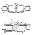
- Figure 1 is a side elevation showing the fitting of the invention being used to join two axially aligned tubes; and
- Figure 2 is a section of the combination of Figure 1, taken essentially along the line 2-2 of Figure 1.
- In the embodiment of Figures 1 and 2, the fitting of the invention is used to join two
tubes second section 14b which are mirror images of one another. The section 14a of the fitting includes an intermediate angled portion 14ʹa having an increased outer diameter with respect to the remaining portion of the sleeve, and having finite length.Sleeve section 14b includes a similar angled portion 14ʹb which is displaced axially from portion 14ʹa. The angled portions 14ʹa and 14ʹb form shoulders which permit a first annulartubular member 16a to be forced over sleeve 14a, and which permit a second annulartubular member 16b to be forced oversleeve 14b by appropriate tools. The fitting itself may be generally similar to the fittings described, for example, in U.S. Patents 4,026,006; 3,893,720; 4,482,174 and 4,061,367. - As stated above, when such fittings are used in aircraft, it is usual for the components of the fittings to be formed of titanium, and to be used for providing joints in the titanium tubes of the hydraulic system of the aircraft. However, as also explained above, it has been found necessary to provide a dry lubricant, formed, for example, of molybdenum disulphide, between the components of the fitting and between the fitting and the tube so as to avoid fretting fatigue cracking due to relative movement between the components and between the fitting and the tube due to galling.
- In the event of lightning strikes on the aircraft, it has been found that, unless appropriate modifications are made, that such lightning strikes create arcing within the fittings which can be disastrous, especially when the fittings are positioned within the fuel tanks.
- This condition cannot be obviated merely by providing an electrically conductive path through any one of the components of the fitting because, as mentioned above, the electric currents resulting from lightning strikes, due to skin effect, are carried by the surfaces of the components. Accordingly, it is necessary to provide an electric path through the fittings from the surface of one component, through a second component, to the surfaces of the tubes.
- This is achieved in accordance with the present invention by the construction shown particularly in Figure 2. It should be noted in Figure 2 that the right-hand section of the fitting is shown in assembled condition, whereas the left-hand section of the fitting is shown prior to the annular
tubular member 16b being drawn up over thesection 14b of the sleeve by an appropriate tool engaging the inner end of annulartubular member 16b and the outer shoulder formed by the increased diameter portion 14'b of the sleeve. - After the annular
tubular member 16a has been forced into the position shown in Figure 2, it has a forward end section 16'a which extends up and over the increased diameter angled portion section 14'a of the corresponding section 14a of the sleeve. The inner surfaces 16'''a of the section 16'a of the annulartubular member 16a is in intimate engagement with the outer surface of the increased diameter angled portion 14ʹa and in electrical contact therewith. The portions 14ʹa and 14ʹb are angled to insure intimate contact withmating surfaces 16‴a and 16‴b of thetubular members - A
layer 20 of dry lubricant is interposed between an intermediate portion of the inner surface of the annulartubular member 16a and the outer surface of the section 14a of the sleeve, as shown. - The inner end of the annular
tubular member 16a has an inner surface with a frusto-conical configuration of reducing diameter toward the rear end of theannular member 16a, this portion being designated 16ʺa. The inner surface of the portion 16ʺa of thetubular member 16a is in intimate contact with the outer surface of the sleeve 14a, and also forces the sleeve 14a against thetube 12 so that its corresponding inner surface is in intimate contact with the outer surface of the tube. - As also shown in Figure 2, the annular
tubular member 16a is forced over sleeve section 14a to be displaced from the inner end of the sleeve section to expose a portion 14ʺa of the sleeve. A second layer of dry lubricant designated 22 is interposed between the portion 14a of the sleeve andtube 12. - With the illustrated configuration of the fitting, any tendency for relative movement between the tube and the fitting, and between the sleeve and the annular tubular member of the fitting does not tend to gall the material of the tube or of the fitting due to the layers of dry lubricant. Accordingly, there is no tendency for fretting fatigue cracking of the tubes or of the components of the fitting.
- Should a lightning strike, or some other happening occur, so as to create high electrical currents along with
tube 12, as mentioned above, such high curents flow around the outer surface of the tube due to skin effect. In the construction shown in Figure 2, the currents find a conductive path from the surface of the tube through the sleeve 14a to the rear of the annulartubular member 16a, and along the annular tubular member to the increased diameter portion 14ʹa of the sleeve. The current then flows through similar paths through the left-hand portion of the fitting. During this current flow, there is no tendency for arcing to occur across the layers of dry lubricant, as was the case in the prior art fittings. - Exhaustive tests of the fitting shown in FIGURES 1 and 2 have revealed that it is immune to arcing for currents up to 45 kilo-amps, as compared with the arcing encountered in the prior art fittings when the currents arose to the level of around 10 kilo-amps.
- The invention provides, therefore, an improved fitting which is particularly useful in aircraft, and which is constructed to be immune from the effects of lighting strikes and the like.
Claims (8)
- A fitting for an electrically conductive tube (12, 10) comprising: an electrically conductive sleeve (14a, 14b) extending over the end of the tube (12, 10) in coaxial relationship therewith; an annular electrically conductive tubular member (16a, 16b) positioned over said sleeve in coaxial relationship therewith for compressing the sleeve against the end of the tube to provide a high-strength fluid-tight joint between the sleeve and the tube; layers of dry lubricant interposed between the inner surface of the tubular member and the outer surface of the sleeve and between the sleeve and the tube; and characterized in that a portion (16''a, 16'''a, 16''b, 16'''b) of the inner surface of said tubular member at each end thereof is in intimate engagement with the outer surface of said sleeve (4a, 4b) and in electrical contact therewith and in that a portion of the inner surface of said sleeve (14a, 14b) is in intimate engagement with the outer surface of said tube (12, 10) and in electrical contact therewith.
- The fitting defined in claim 1, further characterized in that said sleeve (14a, 14b) has a portion (14'a, 14'b) of increased outer diameter and finite length adjacent the inner end of the tube (12, 10) and in which one end (16'a, 16'b) of said tubular member (16a, 16b) extends up and over said increased diameter portion of said sleeve with its inner surface (16''a, 16''b) in intimate engagement and electrical contact with the outer surface of said increased diameter portion of said sleeve.
- The fitting defined in any one of the preceding claims further characterized in that said layer of dry lubricant between the sleeve and the tube is interposed between the inner surface of the rear end portion (14"a) of the sleeve (14a, 14b) and the outer surface of the tube (12, 10) and in that an intermediate portion of the inner surface of the sleeve (14a, 14b) is in intimate engagement and electrical contact with the outer surface of the tube (12, 10).
- The fitting defined in claim 3, in which the tubular member (16a, 16b) is displaced from the inner end of said tube (12, 10) so as to expose said rear end portion (14''a).
- The fitting defined in any one of the preceding claims, further characterized in that the inner surface (16"a) of the portion of said annular tubular member adjacent to the rear end thereof decreases in diameter toward said rear end thereof, the inner surface of rear end of said annular tubular member engaging said sleeve (14a, 14b) forcing the corresponding portion of the sleeve (14a, 14b) against said tube (12, 10) in intimate electrically conductive contact therewith.
- The fitting defined in any one of the preceding claims, further characterized in that the lubricant is formed of an electrically insulating material.
- The fitting defined in any one of the preceding claims, further characterized in that the tube (12, 10), the sleeve (14a, 14b) and the annular tubular member (16a, 16b) are all formed of titanium.
- The fitting defined in any one of the preceding claims in which said dry lubricant is formed of molybdenum disulphide.
Applications Claiming Priority (2)
| Application Number | Priority Date | Filing Date | Title |
|---|---|---|---|
| US06/867,544 US4705302A (en) | 1986-05-28 | 1986-05-28 | Tube fitting |
| US867544 | 1986-05-28 |
Publications (3)
| Publication Number | Publication Date |
|---|---|
| EP0248948A2 EP0248948A2 (en) | 1987-12-16 |
| EP0248948A3 EP0248948A3 (en) | 1988-07-27 |
| EP0248948B1 true EP0248948B1 (en) | 1992-01-22 |
Family
ID=25349989
Family Applications (1)
| Application Number | Title | Priority Date | Filing Date |
|---|---|---|---|
| EP86117463A Expired EP0248948B1 (en) | 1986-05-28 | 1986-12-16 | Tube fitting |
Country Status (5)
| Country | Link |
|---|---|
| US (1) | US4705302A (en) |
| EP (1) | EP0248948B1 (en) |
| CA (1) | CA1285971C (en) |
| DE (2) | DE3683643D1 (en) |
| IL (1) | IL80987A (en) |
Families Citing this family (41)
| Publication number | Priority date | Publication date | Assignee | Title |
|---|---|---|---|---|
| DE8716962U1 (en) * | 1987-12-24 | 1988-02-18 | Hackforth GmbH & Co KG, 4690 Herne | Clamp ring pipe connection for metallic pipes |
| US4925220A (en) * | 1988-12-16 | 1990-05-15 | Cameron Iron Works U.S.A., Inc. | Tubular joint |
| US5088771A (en) * | 1990-02-06 | 1992-02-18 | Sierracin Corporation | Tube union |
| US5219186A (en) * | 1990-02-06 | 1993-06-15 | Sierracin Corporation | Tube union |
| US5388866A (en) * | 1990-03-09 | 1995-02-14 | Lourdes Industries | High pressure coupling with provision for preventing separation of parts and with anti-galling provision |
| US5058930A (en) * | 1990-03-09 | 1991-10-22 | Lourdes Industries | High pressure coupling with provision for preventing separation of parts and with anti-galling provision |
| US5181752A (en) * | 1990-06-26 | 1993-01-26 | Lokring Corporation | Pipe fitting with swage ring locking mechanism |
| US5226677A (en) * | 1991-08-09 | 1993-07-13 | The Johnson Corporation | Rotary joint with extended life seal |
| US5452921A (en) * | 1991-10-31 | 1995-09-26 | The Deutsch Company | Axially swaged fitting |
| US5303958A (en) * | 1991-10-31 | 1994-04-19 | The Deutsch Company | Axially swaged fitting with composite swaging ring |
| US5586568A (en) * | 1993-10-29 | 1996-12-24 | Helmsderfer; John A. | Cover assembly and method for covering undersink piping |
| US5915413A (en) * | 1993-10-29 | 1999-06-29 | Helmsderfer; John A. | Cover assembly with integral measurement indicia for covering undersink piping |
| US5699828A (en) * | 1993-10-29 | 1997-12-23 | Helmsderfer; John A. | Cover assembly with integral measurement indicia for covering undersink piping |
| US5915412A (en) * | 1993-10-29 | 1999-06-29 | Helmsderfer; John A. | Cover assembly for covering undersink piping |
| US5701929A (en) * | 1993-10-29 | 1997-12-30 | Helmsderfer; John A. | Cover assembly having rapid installation features for covering undersink piping |
| US5564463A (en) * | 1993-10-29 | 1996-10-15 | Helmsderfer; John A. | Cover assembly for covering undersink piping |
| US5685328A (en) * | 1993-10-29 | 1997-11-11 | Helmsderfer; John A. | Cover assembly and method for covering undersink piping |
| US5341830A (en) * | 1993-10-29 | 1994-08-30 | Brocar Products, Inc. | Cover assembly and method for covering undersink piping |
| US5901739A (en) * | 1993-10-29 | 1999-05-11 | Helmsderfer; John A. | Cover assembly with integral securing apparatus for covering undersink piping |
| US5795623A (en) * | 1993-10-29 | 1998-08-18 | Mcguire Manufacturing Co., Inc. | Cover assembly and method for covering undersink piping |
| US5405176A (en) * | 1994-02-15 | 1995-04-11 | Mcdonnell Douglas Corporation | High pressure mechanical seal |
| WO1995025185A1 (en) * | 1994-03-17 | 1995-09-21 | Sherritt Inc | Low friction cobalt-based coatings for titanium |
| US5560661A (en) * | 1995-02-10 | 1996-10-01 | Mcdonnell Douglas Corporation | High pressure mechanical seal |
| US5709418A (en) * | 1995-03-20 | 1998-01-20 | Lokring Corporation | Pipe fitting with coupling body and swage ring with kickdown device to prevent reduction in sealing tooth contact force |
| AU1188097A (en) * | 1996-01-11 | 1997-08-01 | Mefi Management Ag | Device and process for the production of an unlockable pipe union |
| USD409728S (en) * | 1997-05-28 | 1999-05-11 | Helmsderfer John A | Insulative cover for undersink piping |
| US6012480A (en) * | 1997-11-03 | 2000-01-11 | Helmsderfer; John A. | Cover assembly for covering undersink piping utilizing sliding cover pieces |
| US6450553B1 (en) * | 1999-11-05 | 2002-09-17 | Mechl Llc | Axial swage fitting for large bore pipes and tubes |
| DE10233968C1 (en) * | 2002-07-25 | 2003-12-18 | Uponor Innovation Ab | Compression sleeve, for pipe compression fitting, includes wax coating over part of its outer surface |
| DE102004020478B3 (en) * | 2004-04-26 | 2005-11-17 | Vulkan Lokring-Rohrverbindungen Gmbh & Co. Kg | Pipe connection with defined sealing effect |
| DE102004055537A1 (en) * | 2004-11-17 | 2006-05-24 | Vulkan Lokring-Rohrverbindungen Gmbh & Co. Kg | Pipe joint with improved strength |
| US20080238090A1 (en) * | 2005-02-14 | 2008-10-02 | Swagelok Company | Fitting With Lubricated Ferrule |
| GB2466098B (en) * | 2005-02-25 | 2010-12-15 | Parker Hannifin Plc | A coupling |
| KR101468788B1 (en) * | 2010-01-04 | 2014-12-03 | 록링 테크놀로지 엘엘씨 | Mechanically attached fitting for use in a sour environment |
| US9033373B2 (en) | 2011-05-04 | 2015-05-19 | The Boeing Company | Axially swaged fitting |
| US9470347B1 (en) | 2011-06-08 | 2016-10-18 | AGS I-Prop., LLC | Fluid line connector |
| US8783735B2 (en) | 2011-10-24 | 2014-07-22 | The Boeing Company | Conductance on hydraulic fittings using a soft metal interlayer |
| CN202852235U (en) * | 2012-06-28 | 2013-04-03 | 天津中瑞邦络克管道联接技术有限公司 | High-pressure resistance fastening pipeline connecting device |
| DE102015102404A1 (en) * | 2015-02-20 | 2016-08-25 | Viega Gmbh & Co. Kg | Fitting with coating, piping system and use of the fitting or piping system |
| CN106764156A (en) * | 2017-04-05 | 2017-05-31 | 北京海泰斯工程设备股份有限公司 | A kind of submarine transport oil pipeline external clamping type self-tightening flange bindiny mechanism |
| CN107237930A (en) * | 2017-06-01 | 2017-10-10 | 苏云飞 | Air-conditioning duct connector |
Family Cites Families (8)
| Publication number | Priority date | Publication date | Assignee | Title |
|---|---|---|---|---|
| DE1089599B (en) * | 1955-06-22 | 1960-09-22 | Jacques Muller | Pipe connection |
| US3149860A (en) * | 1961-01-16 | 1964-09-22 | Boeing Co | High pressure, high temperature reconnectible tube fitting |
| US3675949A (en) * | 1970-05-18 | 1972-07-11 | Mc Donnell Douglas Corp | Coupling fitting for connecting two pipes |
| US4025092A (en) * | 1973-08-20 | 1977-05-24 | Grumman Aerospace Corporation | Self-aligning detachable fitting |
| JPS5647437B2 (en) * | 1974-08-26 | 1981-11-10 | ||
| US4482174A (en) * | 1980-09-15 | 1984-11-13 | Lokring | Apparatus and method for making a tube connection |
| GB2140117B (en) * | 1983-05-17 | 1986-11-05 | Boc Nowsco Ltd | Screw-thread protection |
| CA1208677A (en) * | 1983-06-13 | 1986-07-29 | Dale A. Kneller | Mechanical pipe joint capable of withstanding repeatedly varied internal fluid pressure |
-
1986
- 1986-05-28 US US06/867,544 patent/US4705302A/en not_active Expired - Lifetime
- 1986-12-16 EP EP86117463A patent/EP0248948B1/en not_active Expired
- 1986-12-16 DE DE8686117463T patent/DE3683643D1/en not_active Expired - Lifetime
- 1986-12-16 DE DE198686117463T patent/DE248948T1/en active Pending
- 1986-12-16 IL IL80987A patent/IL80987A/en not_active IP Right Cessation
-
1987
- 1987-01-07 CA CA000526820A patent/CA1285971C/en not_active Expired - Lifetime
Also Published As
| Publication number | Publication date |
|---|---|
| IL80987A (en) | 1991-06-10 |
| DE248948T1 (en) | 1988-06-09 |
| EP0248948A3 (en) | 1988-07-27 |
| US4705302A (en) | 1987-11-10 |
| IL80987A0 (en) | 1987-03-31 |
| CA1285971C (en) | 1991-07-09 |
| DE3683643D1 (en) | 1992-03-05 |
| EP0248948A2 (en) | 1987-12-16 |
Similar Documents
| Publication | Publication Date | Title |
|---|---|---|
| US4705302A (en) | Tube fitting | |
| RU2604470C9 (en) | Improved conductivity on hydraulic system fittings owing to use of intermediate layer of soft metal | |
| GB1454678A (en) | Interconnecting bimetallic tubes | |
| US4260214A (en) | Fault-closable electrical connector | |
| US20090117787A1 (en) | Electrical contact assembly including a sleeve member | |
| JPH0554231B2 (en) | ||
| US4671583A (en) | Fastening device and method for composite structures | |
| US2391457A (en) | Spark plug electrode construction | |
| US9033373B2 (en) | Axially swaged fitting | |
| US6533161B1 (en) | Process for producing a gas-tight soldered joint and use of the process in the production of components with a vacuum-tight casing | |
| US5692853A (en) | Threaded joint construction and rod assembly incorporating same | |
| US6293594B1 (en) | Joining a winding to a connector using a transition ring | |
| DE68909102T2 (en) | Spark plug. | |
| EP3546768A1 (en) | Electromagnetic effect protective fastener with swageable termination body | |
| EP0220397A2 (en) | Tubular bi-metal connector | |
| AU604880B2 (en) | Tubular electrode for plasma torch and plasma torch provided with such electrodes | |
| CN206040252U (en) | Ignition cable prevents ripples cover | |
| CA2104066A1 (en) | Reduced mechanical stress bushing and conductor rod assembly | |
| US4182009A (en) | Electrical igniters | |
| WO2023061862A1 (en) | Bushing comprising a connection terminal, and housing and relay comprising such a bushing | |
| DE112015000475B4 (en) | spark plug | |
| GB461239A (en) | Improvements in or relating to end fittings or joint fittings for electric cables having compressed mineral powder insulation | |
| CN112397966A (en) | Aircraft ignition cable assembling method | |
| US2247420A (en) | Means for joining pipe | |
| DE112019002577T5 (en) | spark plug |
Legal Events
| Date | Code | Title | Description |
|---|---|---|---|
| PUAI | Public reference made under article 153(3) epc to a published international application that has entered the european phase |
Free format text: ORIGINAL CODE: 0009012 |
|
| AK | Designated contracting states |
Kind code of ref document: A2 Designated state(s): DE FR GB IT SE |
|
| ITCL | It: translation for ep claims filed |
Representative=s name: ING. A. GIAMBROCONO & C. S.R.L. |
|
| EL | Fr: translation of claims filed | ||
| DET | De: translation of patent claims | ||
| PUAL | Search report despatched |
Free format text: ORIGINAL CODE: 0009013 |
|
| AK | Designated contracting states |
Kind code of ref document: A3 Designated state(s): DE FR GB IT SE |
|
| 17P | Request for examination filed |
Effective date: 19881118 |
|
| 17Q | First examination report despatched |
Effective date: 19890906 |
|
| GRAA | (expected) grant |
Free format text: ORIGINAL CODE: 0009210 |
|
| ITTA | It: last paid annual fee | ||
| RAP1 | Party data changed (applicant data changed or rights of an application transferred) |
Owner name: AEROQUIP CORPORATION |
|
| AK | Designated contracting states |
Kind code of ref document: B1 Designated state(s): DE FR GB IT SE |
|
| ITF | It: translation for a ep patent filed | ||
| REF | Corresponds to: |
Ref document number: 3683643 Country of ref document: DE Date of ref document: 19920305 |
|
| ET | Fr: translation filed | ||
| PLBE | No opposition filed within time limit |
Free format text: ORIGINAL CODE: 0009261 |
|
| STAA | Information on the status of an ep patent application or granted ep patent |
Free format text: STATUS: NO OPPOSITION FILED WITHIN TIME LIMIT |
|
| 26N | No opposition filed | ||
| EAL | Se: european patent in force in sweden |
Ref document number: 86117463.9 |
|
| REG | Reference to a national code |
Ref country code: GB Ref legal event code: IF02 |
|
| PGFP | Annual fee paid to national office [announced via postgrant information from national office to epo] |
Ref country code: IT Payment date: 20050330 Year of fee payment: 20 |
|
| PGFP | Annual fee paid to national office [announced via postgrant information from national office to epo] |
Ref country code: GB Payment date: 20051104 Year of fee payment: 20 |
|
| PGFP | Annual fee paid to national office [announced via postgrant information from national office to epo] |
Ref country code: FR Payment date: 20051201 Year of fee payment: 20 |
|
| PGFP | Annual fee paid to national office [announced via postgrant information from national office to epo] |
Ref country code: SE Payment date: 20051202 Year of fee payment: 20 |
|
| PGFP | Annual fee paid to national office [announced via postgrant information from national office to epo] |
Ref country code: DE Payment date: 20051230 Year of fee payment: 20 |
|
| PG25 | Lapsed in a contracting state [announced via postgrant information from national office to epo] |
Ref country code: GB Free format text: LAPSE BECAUSE OF EXPIRATION OF PROTECTION Effective date: 20061215 |
|
| REG | Reference to a national code |
Ref country code: GB Ref legal event code: PE20 |
|
| EUG | Se: european patent has lapsed |