EP0248615A2 - Improvements in drilling apparatus - Google Patents
Improvements in drilling apparatus Download PDFInfo
- Publication number
- EP0248615A2 EP0248615A2 EP87304811A EP87304811A EP0248615A2 EP 0248615 A2 EP0248615 A2 EP 0248615A2 EP 87304811 A EP87304811 A EP 87304811A EP 87304811 A EP87304811 A EP 87304811A EP 0248615 A2 EP0248615 A2 EP 0248615A2
- Authority
- EP
- European Patent Office
- Prior art keywords
- core
- barrel
- coated
- fluoropolymer
- core barrel
- Prior art date
- Legal status (The legal status is an assumption and is not a legal conclusion. Google has not performed a legal analysis and makes no representation as to the accuracy of the status listed.)
- Withdrawn
Links
Images
Classifications
-
- E—FIXED CONSTRUCTIONS
- E21—EARTH OR ROCK DRILLING; MINING
- E21B—EARTH OR ROCK DRILLING; OBTAINING OIL, GAS, WATER, SOLUBLE OR MELTABLE MATERIALS OR A SLURRY OF MINERALS FROM WELLS
- E21B25/00—Apparatus for obtaining or removing undisturbed cores, e.g. core barrels or core extractors
- E21B25/10—Formed core retaining or severing means
- E21B25/12—Formed core retaining or severing means of the sliding wedge type
-
- E—FIXED CONSTRUCTIONS
- E21—EARTH OR ROCK DRILLING; MINING
- E21B—EARTH OR ROCK DRILLING; OBTAINING OIL, GAS, WATER, SOLUBLE OR MELTABLE MATERIALS OR A SLURRY OF MINERALS FROM WELLS
- E21B10/00—Drill bits
-
- E—FIXED CONSTRUCTIONS
- E21—EARTH OR ROCK DRILLING; MINING
- E21B—EARTH OR ROCK DRILLING; OBTAINING OIL, GAS, WATER, SOLUBLE OR MELTABLE MATERIALS OR A SLURRY OF MINERALS FROM WELLS
- E21B10/00—Drill bits
- E21B10/02—Core bits
-
- E—FIXED CONSTRUCTIONS
- E21—EARTH OR ROCK DRILLING; MINING
- E21B—EARTH OR ROCK DRILLING; OBTAINING OIL, GAS, WATER, SOLUBLE OR MELTABLE MATERIALS OR A SLURRY OF MINERALS FROM WELLS
- E21B17/00—Drilling rods or pipes; Flexible drill strings; Kellies; Drill collars; Sucker rods; Cables; Casings; Tubings
-
- E—FIXED CONSTRUCTIONS
- E21—EARTH OR ROCK DRILLING; MINING
- E21B—EARTH OR ROCK DRILLING; OBTAINING OIL, GAS, WATER, SOLUBLE OR MELTABLE MATERIALS OR A SLURRY OF MINERALS FROM WELLS
- E21B25/00—Apparatus for obtaining or removing undisturbed cores, e.g. core barrels or core extractors
Definitions
- This invention relates to improvements in drilling apparatus.
- Drilling apparatus is used in a broad sense to cover equipment such as drilling and coring bits, stabilisers, core barrels including inner and outer barrels, bearings and bearing housings, core catchers, core catcher and core barrel substitutes (subs), core barrel extension pieces, junction pieces, drill collars, down hole motors, reamers and substitutes, drill pipe and oil well piping and tubing generally, including oil well production tubing.
- equipment such as drilling and coring bits, stabilisers, core barrels including inner and outer barrels, bearings and bearing housings, core catchers, core catcher and core barrel substitutes (subs), core barrel extension pieces, junction pieces, drill collars, down hole motors, reamers and substitutes, drill pipe and oil well piping and tubing generally, including oil well production tubing.
- drilling apparatus is coated with a layer of a fluoropolymer such as polytetrafluoroethylene, commonly known as PTFE.
- a fluoropolymer such as polytetrafluoroethylene, commonly known as PTFE.
- the core as it is cut enters the inner barrel through the core catcher.
- difficulty may be experienced by the rock core jamming in the mouth of the inner core barrel or core catcher sub or in the core catcher due to the friction between the rock core and the steel inner tube or core catcher or due to the inner core barrel rotating when in contact with the core.
- high pressure may develop in the circulating fluid and lack of penetration or regrinding (or re-cutting) of the rock core will occur.
- the core barrel must then be removed from the drill hole prematurely and the core removed from the barrel before coring can be recommenced.
- the coefficient of friction between the rock core and the steel inner barrel is reduced thus allowing the core to freely enter the inner barrel and to be removed without "freezing".
- the outer surface of the inner barrel and the inner surface of the outer barrel are coated with a fluoropolymer.
- the reduced friction from the coated surface allows higher viscosity fluids and higher volumes of fluid to be used without resulting in the inner barrel rotating.
- the coating of fluoropolymer is a PTFE coating and it is preferably in the form of either a single coat of l8 - 20 microns thickness or two coats each of 5 - l2 microns in thickness.
- Other parts may be coated such as a drill bit carrier or parts of the drill bit itself, or the core catcher sub and other tubes, pipes, collars, sleeves, etc. which are used in the drilling equipment and are liable to come into contact either with the core or with the drilling medium.
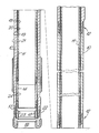
- the apparatus shown in the drawing comprises an outer core barrel l0 and an inner core barrel ll which are normally in sections. One complete section is shown and the joints l2 between each section and the next upper section is also shown.
- a core catcher sub l3 At the lower end of the outer core barrel there is attached a core catcher sub l3. At the lower end of the inner barrel ll is attached an inner barrel breaker sub l4 and below that a core catcher l5. A core bit l6 is attached to the lower end of the outer barrel.
- outer surface 2l of outer barrel l0 may also be coated as may various other parts such as the outer surface 22 of the drill bit, the inner surface 23 of the core catcher and the inner surface 24 of the inner barrel breaker sub.
- any surface may be coated which is liable to be contacted either by a core or by drilling medium.
- this invention it is possible to remove cores from a core barrel with minimum effort and to avoid freezing of the core in the barrel. It is also possible to avoid hydraulic locks and mechanical locks between the rotating outer core barrel and the stationary inner core barrel and thus avoid the core jamming and the necessity of having to remove the whole string in order to free such core jams.
- Oil well production tubing is susceptible to a build-up of salts which stick particularly to the interior surface of the production tubing.
- the tubing is therefore coated, in accordance with the invention, on its interior surface at least, with a layer of PTFE which substantially reduces the build-up of salts.
Landscapes
- Engineering & Computer Science (AREA)
- Life Sciences & Earth Sciences (AREA)
- Geology (AREA)
- Mining & Mineral Resources (AREA)
- Physics & Mathematics (AREA)
- Environmental & Geological Engineering (AREA)
- Fluid Mechanics (AREA)
- General Life Sciences & Earth Sciences (AREA)
- Geochemistry & Mineralogy (AREA)
- Mechanical Engineering (AREA)
- Earth Drilling (AREA)
- Perforating, Stamping-Out Or Severing By Means Other Than Cutting (AREA)
Abstract
Description
- This invention relates to improvements in drilling apparatus.
- An object of the invention is to provide improved and more reliable drilling apparatus which overcomes a number of problems which currently occur in the use of such apparatus. Drilling apparatus is used in a broad sense to cover equipment such as drilling and coring bits, stabilisers, core barrels including inner and outer barrels, bearings and bearing housings, core catchers, core catcher and core barrel substitutes (subs), core barrel extension pieces, junction pieces, drill collars, down hole motors, reamers and substitutes, drill pipe and oil well piping and tubing generally, including oil well production tubing.
- In accordance with the present invention drilling apparatus is coated with a layer of a fluoropolymer such as polytetrafluoroethylene, commonly known as PTFE.
- We now give some examples of the use and importance of the present invention. In core drilling a core of rock is cut by a bit rotating on an outer barrel and the core passes into a non-rotating inner barrel. When the core barrel is lifted from the drill hole the core is retained by a core catcher.
- The core as it is cut enters the inner barrel through the core catcher. Depending upon the type of rock employed, difficulty may be experienced by the rock core jamming in the mouth of the inner core barrel or core catcher sub or in the core catcher due to the friction between the rock core and the steel inner tube or core catcher or due to the inner core barrel rotating when in contact with the core. When the rock core "jams", high pressure may develop in the circulating fluid and lack of penetration or regrinding (or re-cutting) of the rock core will occur. The core barrel must then be removed from the drill hole prematurely and the core removed from the barrel before coring can be recommenced.
- Depending upon the type of rock employed, difficulty may be experienced in removing the rock core from the inner core barrel after the core barrel has been lifted from the drill hole as some rock formations swell when cut and the high friction set up between the rock core and the steel inner tube freezes the rock in the inner core barrel. The normal method of removing the core from the inner core barrel is by gravity or by pumping out the core hydraulically with the use of a piston.
- One attempt to overcome this problem has been to replace the inner core barrel with a fibreglass tube. However, fibreglass tubes are weak and subject to shock and thermal damage in the drill hole.
- By coating the inner barrel surface, particularly the inner surface of the inner barrel, with fluoropolymer the coefficient of friction between the rock core and the steel inner barrel is reduced thus allowing the core to freely enter the inner barrel and to be removed without "freezing".
- Another problem arises in the annular area between the outside of the non-rotating inner barrel and the inside of the rotating outer barrel. This annular area acts as a passage through which all the drill hole circulating medium passes. A medium may for instance be oil-based mud or water based mud. There is a point when circulating high viscosity drill hole medium or high volumes causes the inner barrel to rotate which results in poor core recovery. The reason why the inner barrel rotates within the outer barrel is the hydraulic coupling effect which may occur between the inner and outer barrels. In addition to the hydraulic coupling effect there may in fact be a physical or mechanical coupling due to bending and flexing of the outer barrel in some conditions locking the inner barrel to the outer barrel. Since the inner barrel is normally not required to rotate and the outer barrel is, this can cause jamming of the core in the bit and inner core barrel and, consequently, a disastrous hold up in the drilling operation while the whole barrel is removed so as to remove the jammed core.
- In accordance with the present invention the outer surface of the inner barrel and the inner surface of the outer barrel are coated with a fluoropolymer. The reduced friction from the coated surface allows higher viscosity fluids and higher volumes of fluid to be used without resulting in the inner barrel rotating.
- Preferably the coating of fluoropolymer is a PTFE coating and it is preferably in the form of either a single coat of l8 - 20 microns thickness or two coats each of 5 - l2 microns in thickness.
- Other parts may be coated such as a drill bit carrier or parts of the drill bit itself, or the core catcher sub and other tubes, pipes, collars, sleeves, etc. which are used in the drilling equipment and are liable to come into contact either with the core or with the drilling medium.
- In the accompanying drawing is shown an example of the application of the invention to a core barrel assembly. The core barrel assembly is shown sectioned and is shown in two parts for convenience of illustration, the chain dotted line indicating that the parts were in fact joined in practice.
- The apparatus shown in the drawing comprises an outer core barrel l0 and an inner core barrel ll which are normally in sections. One complete section is shown and the joints l2 between each section and the next upper section is also shown.
- At the lower end of the outer core barrel there is attached a core catcher sub l3. At the lower end of the inner barrel ll is attached an inner barrel breaker sub l4 and below that a core catcher l5. A core bit l6 is attached to the lower end of the outer barrel.
- Various parts of this assembly are shown as coated with PTFE by means of thick lines such as the inner surface l8 of the inner barrel ll, the outer surface l9 of the inner barrel and the inner surface 20 of the outer barrel l0.
- The outer surface 2l of outer barrel l0 may also be coated as may various other parts such as the
outer surface 22 of the drill bit, theinner surface 23 of the core catcher and theinner surface 24 of the inner barrel breaker sub. - In fact any surface may be coated which is liable to be contacted either by a core or by drilling medium.
- By use of this invention, it is possible to remove cores from a core barrel with minimum effort and to avoid freezing of the core in the barrel. It is also possible to avoid hydraulic locks and mechanical locks between the rotating outer core barrel and the stationary inner core barrel and thus avoid the core jamming and the necessity of having to remove the whole string in order to free such core jams.
- Another important application of the present invention is to oil well production tubing. Oil well production tubing is susceptible to a build-up of salts which stick particularly to the interior surface of the production tubing. The tubing is therefore coated, in accordance with the invention, on its interior surface at least, with a layer of PTFE which substantially reduces the build-up of salts.
Claims (8)
Applications Claiming Priority (2)
| Application Number | Priority Date | Filing Date | Title |
|---|---|---|---|
| GB8613582 | 1986-06-04 | ||
| GB868613582A GB8613582D0 (en) | 1985-06-19 | 1986-06-04 | Zrb2-containing sintered cermet drilling apparatus |
Publications (2)
| Publication Number | Publication Date |
|---|---|
| EP0248615A2 true EP0248615A2 (en) | 1987-12-09 |
| EP0248615A3 EP0248615A3 (en) | 1988-11-30 |
Family
ID=10598932
Family Applications (1)
| Application Number | Title | Priority Date | Filing Date |
|---|---|---|---|
| EP87304811A Withdrawn EP0248615A3 (en) | 1986-06-04 | 1987-06-01 | Improvements in drilling apparatus |
Country Status (1)
| Country | Link |
|---|---|
| EP (1) | EP0248615A3 (en) |
Cited By (11)
| Publication number | Priority date | Publication date | Assignee | Title |
|---|---|---|---|---|
| WO1991019075A3 (en) * | 1990-05-31 | 1992-01-09 | Diamant Boart Stratabit Sa | Double-tube core drill for inclined drilling |
| EP0508329A3 (en) * | 1991-04-04 | 1993-02-03 | Baker-Hughes Incorporated | Inner tube stabilizer for a corebarrel |
| BE1015000A5 (en) * | 2000-07-21 | 2004-08-03 | Baker Hughes Inc | Turning drill and method of realization. |
| EP1627128A4 (en) * | 2003-05-07 | 2006-05-24 | Extreme Machining Australia Pt | Stabilising band for a roller assembly |
| WO2008138957A3 (en) * | 2007-05-15 | 2009-01-15 | Shell Int Research | System for drilling a wellbore |
| US7530409B2 (en) | 2002-11-07 | 2009-05-12 | Extreme Machining Australia Pty Ltd. | Rotary roller reamer |
| CN102943642A (en) * | 2012-12-08 | 2013-02-27 | 吉林大学 | Lifting-free borehole bottom rope freezing coring drilling tool and method |
| EP2900899A4 (en) * | 2012-09-25 | 2016-05-11 | Ct Tech Pty Ltd | A core lifter assembly |
| CN107829691A (en) * | 2017-09-25 | 2018-03-23 | 北京探矿工程研究所 | Core tube with internal coating |
| US20190264521A1 (en) * | 2016-03-03 | 2019-08-29 | Halliburton Energy Services, Inc. | Inner barrel shear zone for a coring tool |
| US10767431B2 (en) | 2016-03-03 | 2020-09-08 | Halliburton Energy Services, Inc. | Inner barrel crimping connection for a coring tool |
Family Cites Families (7)
| Publication number | Priority date | Publication date | Assignee | Title |
|---|---|---|---|---|
| DD123550B (en) * | ||||
| US3990751A (en) * | 1975-08-13 | 1976-11-09 | Reed Tool Company | Drill bit |
| SU941542A1 (en) * | 1980-03-17 | 1982-07-07 | Всесоюзный Научно-Исследовательский И Проектный Институт По Нефтепромысловой Химии "Внипинефтепромхим" | Sealing member of packer |
| US4365678A (en) * | 1980-11-28 | 1982-12-28 | Mobil Oil Corporation | Tubular drill string member with contoured circumferential surface |
| BE886911A (en) * | 1980-12-30 | 1981-04-16 | Diamant Boart Sa | METHOD FOR COLLECTING AND HANDLING SURVEY CARROTS, AND TUBE PROVIDED THEREFOR. |
| US4468056A (en) * | 1981-10-05 | 1984-08-28 | The B. F. Goodrich Company | Swivel |
| DE3503494C2 (en) * | 1985-01-31 | 1986-11-27 | Mannesmann AG, 4000 Düsseldorf | Oilfield pipe |
-
1987
- 1987-06-01 EP EP87304811A patent/EP0248615A3/en not_active Withdrawn
Cited By (17)
| Publication number | Priority date | Publication date | Assignee | Title |
|---|---|---|---|---|
| BE1004330A3 (en) * | 1990-05-31 | 1992-11-03 | Diamant Boart Stratabit Sa | Dual core drilling devie. |
| WO1991019075A3 (en) * | 1990-05-31 | 1992-01-09 | Diamant Boart Stratabit Sa | Double-tube core drill for inclined drilling |
| EP0508329A3 (en) * | 1991-04-04 | 1993-02-03 | Baker-Hughes Incorporated | Inner tube stabilizer for a corebarrel |
| BE1015000A5 (en) * | 2000-07-21 | 2004-08-03 | Baker Hughes Inc | Turning drill and method of realization. |
| US7530409B2 (en) | 2002-11-07 | 2009-05-12 | Extreme Machining Australia Pty Ltd. | Rotary roller reamer |
| US7793715B2 (en) | 2002-11-07 | 2010-09-14 | Extreme Machining Australia Pty Ltd. | Rotary roller reamer |
| EP1627128A4 (en) * | 2003-05-07 | 2006-05-24 | Extreme Machining Australia Pt | Stabilising band for a roller assembly |
| GB2461471A (en) * | 2007-05-15 | 2010-01-06 | Shell Int Research | System for drilling a wellbore |
| WO2008138957A3 (en) * | 2007-05-15 | 2009-01-15 | Shell Int Research | System for drilling a wellbore |
| GB2461471B (en) * | 2007-05-15 | 2012-02-15 | Shell Int Research | System for drilling a wellbore |
| EP2900899A4 (en) * | 2012-09-25 | 2016-05-11 | Ct Tech Pty Ltd | A core lifter assembly |
| CN102943642A (en) * | 2012-12-08 | 2013-02-27 | 吉林大学 | Lifting-free borehole bottom rope freezing coring drilling tool and method |
| CN102943642B (en) * | 2012-12-08 | 2015-04-01 | 吉林大学 | Lifting-free borehole bottom rope freezing coring drilling tool and method |
| US20190264521A1 (en) * | 2016-03-03 | 2019-08-29 | Halliburton Energy Services, Inc. | Inner barrel shear zone for a coring tool |
| US10767431B2 (en) | 2016-03-03 | 2020-09-08 | Halliburton Energy Services, Inc. | Inner barrel crimping connection for a coring tool |
| US10941626B2 (en) * | 2016-03-03 | 2021-03-09 | Halliburton Energy Services, Inc. | Inner barrel shear zone for a coring tool |
| CN107829691A (en) * | 2017-09-25 | 2018-03-23 | 北京探矿工程研究所 | Core tube with internal coating |
Also Published As
| Publication number | Publication date |
|---|---|
| EP0248615A3 (en) | 1988-11-30 |
Similar Documents
| Publication | Publication Date | Title |
|---|---|---|
| US11959365B2 (en) | Metal seal for liner drilling | |
| US4825963A (en) | High-pressure waterjet/abrasive particle-jet coring method and apparatus | |
| US2740480A (en) | Pipe wiper | |
| US3986555A (en) | Apparatus for providing a packaged core | |
| US2246418A (en) | Art of well drilling | |
| EP0248615A2 (en) | Improvements in drilling apparatus | |
| US20130319684A1 (en) | Friction reducing stabilizer | |
| US5025864A (en) | Casing hanger wear bushing | |
| US6736224B2 (en) | Drilling system and method suitable for coring and other purposes | |
| US5042600A (en) | Drill pipe with helical ridge for drilling highly angulated wells | |
| Pavković et al. | Review of casing while drilling technology | |
| US4312415A (en) | Reverse circulating tool | |
| Tessari et al. | Casing Drilling–A revolutionary approach to reducing well costs | |
| EP3198107B1 (en) | Axial retention connection for a downhole tool | |
| Kerunwa et al. | OVERVIEW OF THE ADVANCES IN CASING DRILLING TECHNOLOGY. | |
| CN113530453A (en) | Core drilling tool structure with core unblocking function | |
| CN217582091U (en) | Underground drilling-through scraping-milling integrated tool | |
| US20230323742A1 (en) | Circumferential wear bands for oilfield tubulars | |
| US4285408A (en) | Reverse circulating tool | |
| CN215369703U (en) | Core drilling tool structure with core unblocking function | |
| US2621897A (en) | Rotary core drill | |
| US12584383B2 (en) | Metal seal for liner drilling | |
| Elzeky et al. | Successful Deployment of High Risk Monobore Completion in Fracture HPHT Unconventional Reservoir Using Floatation Technology Enhances Well Accessibility | |
| CN117662006A (en) | Method for retrieving old well bore | |
| GB2305953A (en) | Selective core sampling after logging |
Legal Events
| Date | Code | Title | Description |
|---|---|---|---|
| PUAI | Public reference made under article 153(3) epc to a published international application that has entered the european phase |
Free format text: ORIGINAL CODE: 0009012 |
|
| AK | Designated contracting states |
Kind code of ref document: A2 Designated state(s): AT BE CH DE ES FR GB GR IT LI LU NL SE |
|
| PUAL | Search report despatched |
Free format text: ORIGINAL CODE: 0009013 |
|
| RAP1 | Party data changed (applicant data changed or rights of an application transferred) |
Owner name: ORECO DIAMOND PRODUCTS LIMITED |
|
| AK | Designated contracting states |
Kind code of ref document: A3 Designated state(s): AT BE CH DE ES FR GB GR IT LI LU NL SE |
|
| STAA | Information on the status of an ep patent application or granted ep patent |
Free format text: STATUS: THE APPLICATION IS DEEMED TO BE WITHDRAWN |
|
| 18D | Application deemed to be withdrawn |
Effective date: 19890531 |