EP0248486B1 - Supply gripper for gripper weaving looms - Google Patents
Supply gripper for gripper weaving looms Download PDFInfo
- Publication number
- EP0248486B1 EP0248486B1 EP87201009A EP87201009A EP0248486B1 EP 0248486 B1 EP0248486 B1 EP 0248486B1 EP 87201009 A EP87201009 A EP 87201009A EP 87201009 A EP87201009 A EP 87201009A EP 0248486 B1 EP0248486 B1 EP 0248486B1
- Authority
- EP
- European Patent Office
- Prior art keywords
- gripper
- thread
- guiding element
- supply
- thread guiding
- Prior art date
- Legal status (The legal status is an assumption and is not a legal conclusion. Google has not performed a legal analysis and makes no representation as to the accuracy of the status listed.)
- Expired - Lifetime
Links
- 238000009941 weaving Methods 0.000 title claims description 7
- 238000003780 insertion Methods 0.000 claims description 7
- 230000037431 insertion Effects 0.000 claims description 7
- 230000006835 compression Effects 0.000 description 4
- 238000007906 compression Methods 0.000 description 4
- 238000005549 size reduction Methods 0.000 description 2
- 230000007547 defect Effects 0.000 description 1
- 230000000694 effects Effects 0.000 description 1
- 230000002787 reinforcement Effects 0.000 description 1
- 239000013585 weight reducing agent Substances 0.000 description 1
Images

Classifications
-
- D—TEXTILES; PAPER
- D03—WEAVING
- D03D—WOVEN FABRICS; METHODS OF WEAVING; LOOMS
- D03D47/00—Looms in which bulk supply of weft does not pass through shed, e.g. shuttleless looms, gripper shuttle looms, dummy shuttle looms
- D03D47/12—Looms in which bulk supply of weft does not pass through shed, e.g. shuttleless looms, gripper shuttle looms, dummy shuttle looms wherein single picks of weft thread are inserted, i.e. with shedding between each pick
- D03D47/20—Constructional features of the thread-engaging device on the inserters
- D03D47/23—Thread grippers
- D03D47/233—Carrying grippers
Definitions
- the present invention concerns a supply gripper for gripper weaving looms or, in other words, a gripper which is able to bring the weft threads from the insertion side of the shed to half of the shed or still further, in the case of gripper weaving looms.
- the weft thread is taken over half way in the shed by means of a catch gripper which is pulling the weft thread further through the shed up to the opposite side.
- the known supply grippers are mainly composed of a gripper body that is strongly connected to a spear or a sword and whereby a clamping device is mounted in the gripper body in order to keep the weft threads clamped during their transportation through the shed.
- a supply gripper is already known, for instance as already described in the Belgian Patent Nr. 902 141 of the applicant, and the Swiss Patent Nr. 490 544.
- such supply grippers have the disadvantage that they are relatively bulky, complicated and heavy, whereby the maximum weaving speed is kept limited for technical reasons. It is indeed hardly possible to reduce still more the weight of such grippers because their size reduction also results into a size reduction of the clamping device, whereby the possibility to control the clamping force is reduced although it is indeed necessary to have a better control possibility and a stable and fine adjustment of the clamping force in the case of larger weaving speeds.
- the present invention concerns thus, also, a supply gripper with small weight and size without, however, reducing the size of the clamping device, the fastening of the clamping device and the control elements used to this end by comparison with the supply grippers already known in such a way that the characteristics of efficient clamping, of easy transit between the thread presentator and the supply grippers, as well as a quick transit between supply gripper and catch gripper are still maintained.
- the present invention foresees a supply gripper whereby the clamping device is made of a thread guiding element or a wing of the gripper. Consequently, the supply gripper enjoys the advantage that it does not have a separate clamping device - with special parts - and can thus be foreseen with a lighter weight unlike the supply grippers already known.
- Another advantage of the invention contributing also to the weight reduction of the supply gripper is related to the fact that the hinge point of the moving parts of the clamping device, or in this case thus of the involved thread guiding element, may be located nearer to the front end of the supply grippers, whereby this may have a shorter and lighter gripper body.
- An additional advantage of the invention is related to the fact that the hinge point may extend over the full height of the gripper. This way, a strong and wide hinge point is obtained, whereby the compression point occurring for opening the clamping device is always located within the support points of the hinge in such a way that no torsion can be applied to the hinge.
- the present invention consists in a supply gripper for weaving looms having a thread guiding element which is movable towards the gripper body, the clamping device for the weft thread being obtained by the cooperation of the moving thread guiding element with the gripper body whereby the thread guiding element has the shape of a lever that can rotate along the gripper body, and cooperates with the latter one by means of elastic devices, characterised in that the thread guiding element is substantially U-shaped with a bottom plate for guiding the weft thread towards one clamping device, a side plate and a top plate for guiding the weft thread towards thread positioning means at the moment of its insertion into the shed.
- the moving thread guiding element is preferably composed of the gripper wing or the gripper plate that is projecting the most forward.
- control means which are foreseen for adjusting the clamping force. These elements are mounted preferably on the gripper body in order to increase the strength.
- the supply gripper 1 in accordance with the invention is mainly composed of a gripper body 2 that is equipped with a thread guiding element 3, moving towards itself and composed, in the case of the illustrated embodiment, of the gripper wing projecting the most forward.
- the clamping device 4 used for clamping the presented weft thread 5 is composed, according to the invention, by the cooperation of the moving thread guiding element 3 and of the gripper body 2, whereby the clamping force is achieved by means of elastic devices that will be described further herebelow.
- the supply gripper 1 according to figure 1 is designed in order to take an horizontally presented weft thread 5 and to insert it into the shed after that this thread has been taken over by the catch gripper 6.
- the gripper body 2 is mainly composed of a bottom plate 7, a side plate 8 as well as a top plate 9. This gripper body 2 is connected with a spear or a sword on its most rear end 10 in a manner which is not illustrated by figures either directly or indirectly by the use of an intermediate part.
- the thread guiding element 3 has essentially a U-shape and is also composed of a bottom plate 11, a side plate 12 and a top plate 13. This thread guiding element is fastened to the gripper body 2 in such a way that it is able to work as a lever.
- the bottom plates respectively 7 and 11 are connected to each other by means of the hinge point 14 composed for instance of a screw or a similar element.
- the hinge point 14 composed for instance of a screw or a similar element.
- one of the bottom plates, in the present case the bottom plate 7 of the gripper body 2 has a counter sunk area 16, whereon the other bottom plate 11 is supported.
- the clamping device 4 is composed of, on the one hand a jaw 17 that is fastened to the bottom plate 7 of the gripper body 2 and, on the other hand, of a thread-shaped spring 18 that is fastened against the bottom plate 11 of the thread guiding element 3, both in such a way that this thread-shaped spring 18 can cooperate with a V-shaped notch 19 foreseen in the jaw 17.
- the clamping effect of the clamping device 4 can be achieved by means of the action of the lever of the thread guiding element 3 under the influence of the aforesaid elastic devices that are composed of a spring 20, in the present case a compression spring acting between the end of the thread guiding element 3 extending the most in the rear direction and the side plate 8 of the gripper body 2.
- the rotatable thread guiding element 3 is also equipped with an opening compression point 21 that is composed, in the embodiment of figure 1, of a protruding part like a welded piece and that can be actuated during the movement of the gripper or not actuated by means of a cam that is not illustrated in the figures.
- the clamping device 4 contains preferably control means 22 in order to adjust and/or to control the pre-stress in the thread-shaped spring 18.
- control devices 20 are already known and have been described in the Belgian patent 902 141 of the applicant. Consequently any further description would be unnecessary.
- the jaw 17 can be foreseen with adjustment possibilities.
- the end 23 located the most forward of the supply gripper 1 gets an adequate shape in order that the horizontally presented weft thread 5 can be guided too between the clamping device 4.
- FIG. 1 The working of the supply gripper 1 is clearly illustrated on figure 1.
- the thread 5 When the thread 5 is horizontally presented it is moved between the top edge of the side plate 12 of the thread guiding element 3 and the bottom side of the top plate 9 of the gripper body 2 and is guided along the edge 24 of the latter top plate 9 into the clamping device 4. While the supply gripper 1 is moving through the shed, the thread 5 is extending from the clamping device 4 in the rearwards direction, whereby the location of the thread 5 is determined by a cutout 25 in the top plate 13 of the thread guiding element 3.
- Figures 3 and 4 illustrate a supply gripper 1 that must be applied in the case of vertically or skew upwards presented weft thread 5.
- the gripper body 2 is mainly limited in this case to a bottom plate 26.
- a plate 27 may possibly be mounted perpendicularly to the former one in order to achieve some reinforcement, while this plate has also a seat 28 wherein the aforesaid spring 20 can be mounted.
- the thread guiding element 3 has also the shape of a lever that is rotatably mounted on a hinge point 14, whereby this lever is made of a bottom plate 11, a side plate 12 and a top plate 13.
- the most rear lever arm 29 is connected to the side plate 12 by means of screw elements 31 and 32.
- the clamping device 4 shows some difference towards the embodiment of figure 1, because in this case the jaw 17 is connected with the thread guiding element 3 while the thread-shaped spring 18 is secured on the gripper body 2.
- the jaw 17 is screwed in this case against the bottom plate of the thread guiding element 3, while the thread-shaped spring 18 is fastened for instance by means of the flat end 33 and a screw 34 against the bottom plate 26.
- the thread-shaped spring 18 can also be equipped with control means like adjustment screws 35 and 36 in order to adjust respectively the position of the spring 18 and the pre-stress in this spring.
- the fact that the control means 35 and 36 are secured on the gripper body 2 results in a stable control. As such control means have already been sufficiently described in the Belgian Patent Nr. 902 141, they are just schematically illustrated on figure 3 for reasons of simplicity.
- the part 37 of the thread-shaped spring 18 located against the bottom plate 26 as well as the control means for this spring can be equipped with a protection 38. This way, in the case of accidental impact of the catch gripper 6 against the fastening of the spring 18 and or its control means, the risk of deformation of the spring or of defect of the system is avoided.
- the part 37 of the thread-shaped spring 18 will be preferably mounted in a cutout 39 in the bottom plate 26.
- the protection 38 can be composed of a simple cover plate.
- the embodiment described hereabove has the advantage that the gripper body 2 can have the same size as the spear and can also be a part of it. In the latter case, the hinge point of the thread guiding element 3 and the aforesaid cutout 39 can be located in the end of the spear itself.
- This embodiment has also the advantage that the hinge point 14 of the thread guiding element 3 may be very strong and broad.
- the size of the hinge is indeed only limited by the sizes of the gripper itself.
- this hinge point can also be mounted outside the extension of the path of the catch gripper 6, whereby in the case of possible loosening of the catch gripper 6 the latter one can move simply along the supply gripper 1 without damaging any part of it.
- the supply gripper 1 of figures 3 and 4 have also the advantage that, if the catch gripper 6 is colliding against the thread guiding element 3 because of undesirable circumstances, the clamping device 4 will be kept closed and the weft thread 5 will not be lost.
- the aforesaid cutout 25 or the recess 42 in the top plate 13 of the thread guiding element 3 may be replaced by a hook element pushed from the top plate 13 and having the shape of a triangular lip 43.
- the location of the thread in relationship with the supply gripper 1 during its movement in the shed is determined by the edge 44 of the top plate 13 which is bent in upwards direction.
- FIGs 9 to 12 are illustrating an embodiment of the supply gripper 1 according to the invention, whereby the working principle is mainly corresponding to the embodiment according to figure 3, while the design is derived from the embodiment according to figure 1.
- This supply gripper 1 is designed for application in the case of horizontal presentation of the thread.
- the thread-shaped spring 18 and the control means 22 are thus also fastened on the gripper body 2, while the jaw 17 is mounted on the thread guiding element 3.
- the spring 2 is consequently a pulling spring.
- the top plate 9 is designed in such a way that the hinge point 14 comprises a connection on the top side as well as on the bottom side of the supply gripper 1, respectively between the bottom plates 7 and 11 and the top plates 9 and 13. As the hinge point 13 is really extending over the full height, no twisting can occur when the compression point 21 is actuated.
- the hinge point 14 can also have a continuous profile for instance by means of a shaft of another element which is extending in cross-direction through the supply gripper 1.
- stops which are not illustrated on the figures can also be foreseen in order to limit the movement of the rotatable thread guiding element 3 if the thread-shaped spring 18 or the spring 20 could be loosened or broken, in order to avoid that the thread guiding element 3 comes into contact with the warp threads.
Landscapes
- Engineering & Computer Science (AREA)
- Textile Engineering (AREA)
- Looms (AREA)
Description
- The present invention concerns a supply gripper for gripper weaving looms or, in other words, a gripper which is able to bring the weft threads from the insertion side of the shed to half of the shed or still further, in the case of gripper weaving looms.
- As already known, the weft thread is taken over half way in the shed by means of a catch gripper which is pulling the weft thread further through the shed up to the opposite side.
- The known supply grippers are mainly composed of a gripper body that is strongly connected to a spear or a sword and whereby a clamping device is mounted in the gripper body in order to keep the weft threads clamped during their transportation through the shed. Such a supply gripper is already known, for instance as already described in the Belgian Patent Nr. 902 141 of the applicant, and the Swiss Patent Nr. 490 544.
- By using a separate cling device, such supply grippers have the disadvantage that they are relatively bulky, complicated and heavy, whereby the maximum weaving speed is kept limited for technical reasons. It is indeed hardly possible to reduce still more the weight of such grippers because their size reduction also results into a size reduction of the clamping device, whereby the possibility to control the clamping force is reduced although it is indeed necessary to have a better control possibility and a stable and fine adjustment of the clamping force in the case of larger weaving speeds.
- Quite obviously, any further reduction of the size of such supply grippers, in order to reduce their weight does not yield any more advantage at a given stage.
- If such supply grippers are made with relatively small sizes, these also offer the disadvantage that the fastening of the clamping device and namely the hinge point of the clamping lever becomes very weak while the hinge becomes very sensible for wear. Moreover, such a hinge is too weak in such a case for resisting to the twisting occurring with the most embodiments when the clamping device is opened, because the pressure point for actuating the clamping lever is located outside the hinge plane.
- The present invention concerns thus, also, a supply gripper with small weight and size without, however, reducing the size of the clamping device, the fastening of the clamping device and the control elements used to this end by comparison with the supply grippers already known in such a way that the characteristics of efficient clamping, of easy transit between the thread presentator and the supply grippers, as well as a quick transit between supply gripper and catch gripper are still maintained.
- To this end the present invention foresees a supply gripper whereby the clamping device is made of a thread guiding element or a wing of the gripper. Consequently, the supply gripper enjoys the advantage that it does not have a separate clamping device - with special parts - and can thus be foreseen with a lighter weight unlike the supply grippers already known.
- Another advantage of the invention contributing also to the weight reduction of the supply gripper is related to the fact that the hinge point of the moving parts of the clamping device, or in this case thus of the involved thread guiding element, may be located nearer to the front end of the supply grippers, whereby this may have a shorter and lighter gripper body.
- An additional advantage of the invention is related to the fact that the hinge point may extend over the full height of the gripper. This way, a strong and wide hinge point is obtained, whereby the compression point occurring for opening the clamping device is always located within the support points of the hinge in such a way that no torsion can be applied to the hinge.
- In order to obtain the aforesaid advantages the present invention consists in a supply gripper for weaving looms having a thread guiding element which is movable towards the gripper body, the clamping device for the weft thread being obtained by the cooperation of the moving thread guiding element with the gripper body whereby the thread guiding element has the shape of a lever that can rotate along the gripper body, and cooperates with the latter one by means of elastic devices, characterised in that the thread guiding element is substantially U-shaped with a bottom plate for guiding the weft thread towards one clamping device, a side plate and a top plate for guiding the weft thread towards thread positioning means at the moment of its insertion into the shed.
- The moving thread guiding element is preferably composed of the gripper wing or the gripper plate that is projecting the most forward. Moreover, there are still several control means which are foreseen for adjusting the clamping force. These elements are mounted preferably on the gripper body in order to increase the strength.
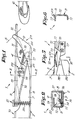
- In order that the characteristics of the invention are better understood, a few preferred embodiments will be described hereafter by way of examples without any limitative character and with reference to the figures in appendix representing respectively:
- figure 1 a top view of a supply gripper according to the invention;
- figure 2 a cross-section along line II - II of figure 1;
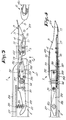
- figure 3 a top view of another embodiment of the supply gripper;
- figure 4 the supply gripper of figure 3 in side view along the arrow F4;
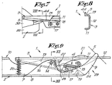
- figure 5 the illustration of an alternative solution of the part indicated by F5 on figure 3;
- figure 6 a cross-section along line VI - VI of figure 5;
- figures 7 and 8 illustrations of still another alternative solution corresponding to figures 5 and 6;
- figure 9, a top view of still another embodiment of the supply gripper;
- figure 10 the moving thread guiding element of the supply gripper of figure 9;
- figure 11 the gripper body of the supply gripper of figure 9;
- figure 12 a cross-section along line XII - XII of figure 9.
- As illustrated on the figures, the
supply gripper 1 in accordance with the invention is mainly composed of agripper body 2 that is equipped with athread guiding element 3, moving towards itself and composed, in the case of the illustrated embodiment, of the gripper wing projecting the most forward. Theclamping device 4 used for clamping the presentedweft thread 5 is composed, according to the invention, by the cooperation of the movingthread guiding element 3 and of thegripper body 2, whereby the clamping force is achieved by means of elastic devices that will be described further herebelow. - The
supply gripper 1 according to figure 1 is designed in order to take an horizontally presentedweft thread 5 and to insert it into the shed after that this thread has been taken over by thecatch gripper 6. - The
gripper body 2 is mainly composed of abottom plate 7, aside plate 8 as well as atop plate 9. Thisgripper body 2 is connected with a spear or a sword on its mostrear end 10 in a manner which is not illustrated by figures either directly or indirectly by the use of an intermediate part. - The
thread guiding element 3 has essentially a U-shape and is also composed of abottom plate 11, aside plate 12 and atop plate 13. This thread guiding element is fastened to thegripper body 2 in such a way that it is able to work as a lever. To this end, the bottom plates respectively 7 and 11 are connected to each other by means of thehinge point 14 composed for instance of a screw or a similar element. In order to achieve asmooth bottom side 15, one of the bottom plates, in the present case thebottom plate 7 of thegripper body 2, has acounter sunk area 16, whereon theother bottom plate 11 is supported. - The
clamping device 4 is composed of, on the one hand ajaw 17 that is fastened to thebottom plate 7 of thegripper body 2 and, on the other hand, of a thread-shaped spring 18 that is fastened against thebottom plate 11 of thethread guiding element 3, both in such a way that this thread-shaped spring 18 can cooperate with a V-shaped notch 19 foreseen in thejaw 17. The clamping effect of theclamping device 4 can be achieved by means of the action of the lever of thethread guiding element 3 under the influence of the aforesaid elastic devices that are composed of aspring 20, in the present case a compression spring acting between the end of thethread guiding element 3 extending the most in the rear direction and theside plate 8 of thegripper body 2. The rotatablethread guiding element 3 is also equipped with anopening compression point 21 that is composed, in the embodiment of figure 1, of a protruding part like a welded piece and that can be actuated during the movement of the gripper or not actuated by means of a cam that is not illustrated in the figures. - The
clamping device 4 contains preferably control means 22 in order to adjust and/or to control the pre-stress in the thread-shaped spring 18. Thesecontrol devices 20 are already known and have been described in the Belgian patent 902 141 of the applicant. Consequently any further description would be unnecessary. - As already described in this patent, the
jaw 17 can be foreseen with adjustment possibilities. - Quite obviously, the
end 23 located the most forward of thesupply gripper 1 gets an adequate shape in order that the horizontally presentedweft thread 5 can be guided too between theclamping device 4. - The working of the
supply gripper 1 is clearly illustrated on figure 1. When thethread 5 is horizontally presented it is moved between the top edge of theside plate 12 of thethread guiding element 3 and the bottom side of thetop plate 9 of thegripper body 2 and is guided along theedge 24 of the lattertop plate 9 into theclamping device 4. While thesupply gripper 1 is moving through the shed, thethread 5 is extending from theclamping device 4 in the rearwards direction, whereby the location of thethread 5 is determined by acutout 25 in thetop plate 13 of thethread guiding element 3. - When the
weft thread 5 is presented, an advantage is resulting from the fact that, because thethread 5 is guided over theside plate 12, the rotatablethread guiding element 3 is pushed against thegripper body 2 by the taut thread in such a way that theclamping device 4 has a tendency to open. Also, when thethread 5 is taken over by thecatch gripper 6, an advantage is occurring because the thread is pulled downwards on thejaw 17 without working against theclamping device 4. - Figures 3 and 4 illustrate a
supply gripper 1 that must be applied in the case of vertically or skew upwards presentedweft thread 5. - The
gripper body 2 is mainly limited in this case to abottom plate 26. Aplate 27 may possibly be mounted perpendicularly to the former one in order to achieve some reinforcement, while this plate has also aseat 28 wherein theaforesaid spring 20 can be mounted. - In this embodiment, the
thread guiding element 3 has also the shape of a lever that is rotatably mounted on ahinge point 14, whereby this lever is made of abottom plate 11, aside plate 12 and atop plate 13. The mostrear lever arm 29 is connected to theside plate 12 by means ofscrew elements - The
clamping device 4 shows some difference towards the embodiment of figure 1, because in this case thejaw 17 is connected with thethread guiding element 3 while the thread-shaped spring 18 is secured on thegripper body 2. Thejaw 17 is screwed in this case against the bottom plate of thethread guiding element 3, while the thread-shaped spring 18 is fastened for instance by means of theflat end 33 and ascrew 34 against thebottom plate 26. The thread-shaped spring 18 can also be equipped with control means likeadjustment screws spring 18 and the pre-stress in this spring. The fact that the control means 35 and 36 are secured on thegripper body 2 results in a stable control. As such control means have already been sufficiently described in the Belgian Patent Nr. 902 141, they are just schematically illustrated on figure 3 for reasons of simplicity. - As illustrated in the partial cross-section of figure 4, the
part 37 of the thread-shaped spring 18 located against thebottom plate 26 as well as the control means for this spring can be equipped with aprotection 38. This way, in the case of accidental impact of thecatch gripper 6 against the fastening of thespring 18 and or its control means, the risk of deformation of the spring or of defect of the system is avoided. Thepart 37 of the thread-shapedspring 18 will be preferably mounted in acutout 39 in thebottom plate 26. Theprotection 38 can be composed of a simple cover plate. - The embodiment described hereabove has the advantage that the
gripper body 2 can have the same size as the spear and can also be a part of it. In the latter case, the hinge point of thethread guiding element 3 and theaforesaid cutout 39 can be located in the end of the spear itself. - This embodiment has also the advantage that the
hinge point 14 of thethread guiding element 3 may be very strong and broad. The size of the hinge is indeed only limited by the sizes of the gripper itself. - According to an alternative solution which is not illustrated on the figures, this hinge point can also be mounted outside the extension of the path of the
catch gripper 6, whereby in the case of possible loosening of thecatch gripper 6 the latter one can move simply along thesupply gripper 1 without damaging any part of it. - Compared with the first described embodiment, the
supply gripper 1 of figures 3 and 4 have also the advantage that, if thecatch gripper 6 is colliding against thethread guiding element 3 because of undesirable circumstances, theclamping device 4 will be kept closed and theweft thread 5 will not be lost. - Moreover, with the last embodiment, it is unimportant for the correct overtake of the
weft thread 5 from theclamping device 4, to choose along which side theopening 4 of the catch gripper is located in relationship with thethread guiding element 3. Because the supply gripper is completely open on oneside 41 and half open on the top side, the advantage is achieved that thecatch gripper 6, if it is mounted as illustrated on figure 3, does not undergo any size limitation caused by the space made available in thesupply gripper 1. - The working of the last described embodiment can be easily understood by looking at figures 3 and 4. When the
supply gripper 1 is moving in the shed, the position of thethread 5 is determined in this case by arecess 42 in thetop plate 13. - According to an alternative solution illustrated on figures 5 and 6, the
aforesaid cutout 25 or therecess 42 in thetop plate 13 of thethread guiding element 3 may be replaced by a hook element pushed from thetop plate 13 and having the shape of a triangular lip 43. According to still another alternative solution illustrated on figures 7 and 8, the location of the thread in relationship with thesupply gripper 1 during its movement in the shed is determined by theedge 44 of thetop plate 13 which is bent in upwards direction. - Figures 9 to 12 are illustrating an embodiment of the
supply gripper 1 according to the invention, whereby the working principle is mainly corresponding to the embodiment according to figure 3, while the design is derived from the embodiment according to figure 1. Thissupply gripper 1 is designed for application in the case of horizontal presentation of the thread. - In this embodiment, the thread-shaped
spring 18 and the control means 22 are thus also fastened on thegripper body 2, while thejaw 17 is mounted on thethread guiding element 3. Thespring 2 is consequently a pulling spring. - The
top plate 9 is designed in such a way that thehinge point 14 comprises a connection on the top side as well as on the bottom side of thesupply gripper 1, respectively between thebottom plates top plates hinge point 13 is really extending over the full height, no twisting can occur when thecompression point 21 is actuated. Thehinge point 14 can also have a continuous profile for instance by means of a shaft of another element which is extending in cross-direction through thesupply gripper 1. - When the
thread guiding element 3 is pushed open at the moment that thethread 5 is running into thegripper 1, for instance, by pushing with a cam which is not illustrated on theopenings pressure points 21, it is possible with this latter embodiment to increase the size of the opening between theside plate 12 and thetop plate 9, whereby thethread 5 can more easily penetrate into the gripper. This way, and for the same opening, it is possible to achieve a better protection of theend 9 towards the warp threads because the top of thetop plate 9 can be taken lower, respective to theside plate 12. - Quite obviously, stops which are not illustrated on the figures can also be foreseen in order to limit the movement of the rotatable
thread guiding element 3 if the thread-shapedspring 18 or thespring 20 could be loosened or broken, in order to avoid that thethread guiding element 3 comes into contact with the warp threads. - The present invention is by no means limited to the embodiments described by way of example and illustrated on the figures in appendix, but such a supply gripper can also be put into practice with several shapes and sizes without leaving from the scope of the present invention.
Claims (11)
Applications Claiming Priority (2)
| Application Number | Priority Date | Filing Date | Title |
|---|---|---|---|
| BE2060987 | 1986-06-03 | ||
| BE2/60987A BE904862A (en) | 1986-06-03 | 1986-06-03 | Weft yarn insert gripper of weaving loom has yarn guide element - movable w.r.t gripper body, pref. pivoted and closure spring-loaded w.r.t. body |
Publications (2)
| Publication Number | Publication Date |
|---|---|
| EP0248486A1 EP0248486A1 (en) | 1987-12-09 |
| EP0248486B1 true EP0248486B1 (en) | 1990-01-17 |
Family
ID=3865808
Family Applications (1)
| Application Number | Title | Priority Date | Filing Date |
|---|---|---|---|
| EP87201009A Expired - Lifetime EP0248486B1 (en) | 1986-06-03 | 1987-05-29 | Supply gripper for gripper weaving looms |
Country Status (3)
| Country | Link |
|---|---|
| US (1) | US4860800A (en) |
| EP (1) | EP0248486B1 (en) |
| ES (1) | ES2012386B3 (en) |
Families Citing this family (11)
| Publication number | Priority date | Publication date | Assignee | Title |
|---|---|---|---|---|
| IT1238606B (en) * | 1990-01-26 | 1993-08-18 | Nuovo Pignone Spa | PERFECTED WEFT STITCHING DEVICE IN A TEXTILE FRAME WITHOUT SHUTTLE |
| EP0526390B1 (en) * | 1991-07-24 | 1996-09-11 | Sulzer RàTi Ag | Gripper loom with an insert device which is adjustable according to the thread properties |
| IT1251304B (en) * | 1991-09-11 | 1995-05-08 | Somet Soc Mec Tessile | PAIR OF CARRIER-TRACTOR PLIERS FOR WEAVING FRAMES WITHOUT SHUTTLE WITH TRANSPORT OF THE WEFT IN AN OBLIQUE AND VERTICAL PLAN |
| IT1255629B (en) * | 1992-05-22 | 1995-11-09 | Luciano Corain | TRACTION GRIPPER PERFECTED FOR TEXTILE FRAME |
| IT1290838B1 (en) * | 1996-02-27 | 1998-12-14 | Nuovo Pignone Spa | PERFECTED CONDUCT CLAMP FOR CLAMP TEXTILE FRAME |
| EP0811712B1 (en) * | 1996-06-07 | 2000-04-05 | Sulzer Textil Ag | Thread clamp for a feeding gripper and feeding gripper with such a clamp |
| BE1010943A3 (en) * | 1997-02-24 | 1999-03-02 | Picanol Nv | Rapier WITH SOME GUIDANCE RESOURCES. |
| DE19713628A1 (en) * | 1997-04-02 | 1998-10-08 | Picanol Nv | Rapier weaving machine |
| BE1011480A3 (en) * | 1997-10-03 | 1999-10-05 | Picanol Nv | GRAVELER FOR A GRAPER WEAVING MACHINE. |
| DE502006002809D1 (en) * | 2006-01-06 | 2009-03-26 | Sultex Ag | Bringer rapier for a rapier loom |
| BE1024494B1 (en) * | 2016-08-11 | 2018-03-12 | Picanol Naamloze Vennootschap | GRIPPER TIE AND GRIPER FOR A GRIPPER WEAVING MACHINE |
Family Cites Families (8)
| Publication number | Priority date | Publication date | Assignee | Title |
|---|---|---|---|---|
| DE2536022C3 (en) * | 1975-08-13 | 1979-09-20 | Jean Guesken Gmbh & Co Kg, 4060 Viersen | Weft thread insertion device for weaving machines with oppositely movable gripper bars |
| CH616713A5 (en) * | 1977-06-09 | 1980-04-15 | Albatex Ag | |
| IT1095254B (en) * | 1978-04-07 | 1985-08-10 | Somet Meccanica Tessile S P A | CARRIER GRIPPER FOR WEAVING FRAMES WITH CONTINUOUS WEFT FEED |
| CH634615A5 (en) * | 1979-01-30 | 1983-02-15 | Rueti Ag Maschf | Feed gripper for weaving machines with extraction of the weft thread from fixed bobbins |
| DD142724A1 (en) * | 1979-03-27 | 1980-07-09 | Harry Toepel | GRIPPER PAIR FOR SHOOTING ON A PROTECTIVE WEAVING MACHINE |
| US4284108A (en) * | 1979-11-13 | 1981-08-18 | Adolph Saurer Limited | Thread gripper |
| IT1132844B (en) * | 1980-09-15 | 1986-07-09 | Nuovo Pignone Spa | IMPROVEMENTS IN THE GRINDING PLIERS FOR TEXTILE FRAMES |
| BE902141A (en) * | 1985-04-09 | 1985-10-09 | Picanol Nv | IMPROVED GRAPHERS FOR WEAVING MACHINES. |
-
1987
- 1987-05-29 EP EP87201009A patent/EP0248486B1/en not_active Expired - Lifetime
- 1987-05-29 ES ES87201009T patent/ES2012386B3/en not_active Expired - Lifetime
- 1987-06-02 US US07/056,723 patent/US4860800A/en not_active Expired - Fee Related
Also Published As
| Publication number | Publication date |
|---|---|
| ES2012386B3 (en) | 1990-03-16 |
| EP0248486A1 (en) | 1987-12-09 |
| US4860800A (en) | 1989-08-29 |
Similar Documents
| Publication | Publication Date | Title |
|---|---|---|
| EP0248486A1 (en) | Supply gripper for gripper weaving looms | |
| JPH032974B2 (en) | ||
| US4587998A (en) | Filling-thread insertion gripper for a rapier weaving machine | |
| US4040454A (en) | Drawing gripper for gripping and transporting weft yarns in continuous weft feed looms | |
| US3998251A (en) | Clamping device at gripper heads for shuttleless looms | |
| US4913195A (en) | Gripper loom | |
| US4108214A (en) | Weaving loom with tension adjustor for warp edge threads | |
| EP0011380B1 (en) | Weft cutting device in a shuttleless loom | |
| US20120125475A1 (en) | Gripper Head of a Weaving Machine | |
| US4398568A (en) | Apparatus for stopping and resetting a loom | |
| US4062382A (en) | Extending carrier for looms with removal of the filling yarn from stationary bobbins | |
| US6179014B1 (en) | Drawing gripper for a rapier loom for receiving and positioning a filling to be inserted into a loom shed | |
| US4834147A (en) | Weft thread cutting mechanism for shuttleless looms | |
| US3854506A (en) | Gripper shuttle | |
| US4949762A (en) | Weft gripper for shuttleless loom | |
| US4143683A (en) | Device for controlling and cutting the weft threads in looms with weft inserters | |
| US3626991A (en) | Selvage-forming motion operable in conjunction with a filling-cutting mechanism of a shuttleless loom | |
| US4276912A (en) | Weft thread control device for a weaving loom with removal of the weft thread from a supply spool beside the loom | |
| US3441061A (en) | Weft pull and release device for weaving looms having no shuttles | |
| GB2059456A (en) | Device for transferring a weft thread in a shuttleless power-loom | |
| GB2140831A (en) | A shuttleless weaving loom | |
| US4646790A (en) | Cutting mechanism for a weaving machine | |
| US3851677A (en) | Shuttle loom | |
| US2763295A (en) | Shuttle checking apparatus | |
| US3012587A (en) | Automatic nipper temple for weaving looms |
Legal Events
| Date | Code | Title | Description |
|---|---|---|---|
| PUAI | Public reference made under article 153(3) epc to a published international application that has entered the european phase |
Free format text: ORIGINAL CODE: 0009012 |
|
| AK | Designated contracting states |
Kind code of ref document: A1 Designated state(s): CH DE ES FR GB IT LI LU NL |
|
| 17P | Request for examination filed |
Effective date: 19871221 |
|
| 17Q | First examination report despatched |
Effective date: 19890111 |
|
| GRAA | (expected) grant |
Free format text: ORIGINAL CODE: 0009210 |
|
| AK | Designated contracting states |
Kind code of ref document: B1 Designated state(s): CH DE ES FR GB IT LI LU NL |
|
| REF | Corresponds to: |
Ref document number: 3761443 Country of ref document: DE Date of ref document: 19900222 |
|
| ITF | It: translation for a ep patent filed | ||
| ET | Fr: translation filed | ||
| PG25 | Lapsed in a contracting state [announced via postgrant information from national office to epo] |
Ref country code: LU Free format text: LAPSE BECAUSE OF NON-PAYMENT OF DUE FEES Effective date: 19900531 |
|
| PGFP | Annual fee paid to national office [announced via postgrant information from national office to epo] |
Ref country code: NL Payment date: 19900531 Year of fee payment: 4 |
|
| PGFP | Annual fee paid to national office [announced via postgrant information from national office to epo] |
Ref country code: LU Payment date: 19900608 Year of fee payment: 4 |
|
| PLBE | No opposition filed within time limit |
Free format text: ORIGINAL CODE: 0009261 |
|
| STAA | Information on the status of an ep patent application or granted ep patent |
Free format text: STATUS: NO OPPOSITION FILED WITHIN TIME LIMIT |
|
| 26N | No opposition filed | ||
| ITTA | It: last paid annual fee | ||
| PG25 | Lapsed in a contracting state [announced via postgrant information from national office to epo] |
Ref country code: NL Effective date: 19911201 |
|
| NLV4 | Nl: lapsed or anulled due to non-payment of the annual fee | ||
| PGFP | Annual fee paid to national office [announced via postgrant information from national office to epo] |
Ref country code: GB Payment date: 19920508 Year of fee payment: 6 |
|
| PGFP | Annual fee paid to national office [announced via postgrant information from national office to epo] |
Ref country code: FR Payment date: 19930419 Year of fee payment: 7 |
|
| PGFP | Annual fee paid to national office [announced via postgrant information from national office to epo] |
Ref country code: CH Payment date: 19930429 Year of fee payment: 7 |
|
| PGFP | Annual fee paid to national office [announced via postgrant information from national office to epo] |
Ref country code: ES Payment date: 19930513 Year of fee payment: 7 |
|
| PG25 | Lapsed in a contracting state [announced via postgrant information from national office to epo] |
Ref country code: GB Effective date: 19930529 |
|
| PGFP | Annual fee paid to national office [announced via postgrant information from national office to epo] |
Ref country code: DE Payment date: 19930618 Year of fee payment: 7 |
|
| GBPC | Gb: european patent ceased through non-payment of renewal fee |
Effective date: 19930529 |
|
| PG25 | Lapsed in a contracting state [announced via postgrant information from national office to epo] |
Ref country code: ES Free format text: LAPSE BECAUSE OF NON-PAYMENT OF DUE FEES Effective date: 19940530 |
|
| PG25 | Lapsed in a contracting state [announced via postgrant information from national office to epo] |
Ref country code: LI Effective date: 19940531 Ref country code: CH Effective date: 19940531 |
|
| PG25 | Lapsed in a contracting state [announced via postgrant information from national office to epo] |
Ref country code: FR Effective date: 19950131 |
|
| REG | Reference to a national code |
Ref country code: CH Ref legal event code: PL |
|
| PG25 | Lapsed in a contracting state [announced via postgrant information from national office to epo] |
Ref country code: DE Effective date: 19950201 |
|
| REG | Reference to a national code |
Ref country code: FR Ref legal event code: ST |
|
| REG | Reference to a national code |
Ref country code: ES Ref legal event code: FD2A Effective date: 19990301 |
|
| PG25 | Lapsed in a contracting state [announced via postgrant information from national office to epo] |
Ref country code: IT Free format text: LAPSE BECAUSE OF NON-PAYMENT OF DUE FEES;WARNING: LAPSES OF ITALIAN PATENTS WITH EFFECTIVE DATE BEFORE 2007 MAY HAVE OCCURRED AT ANY TIME BEFORE 2007. THE CORRECT EFFECTIVE DATE MAY BE DIFFERENT FROM THE ONE RECORDED. Effective date: 20050529 |